Vitality KF-1860 User manual

Owner’s Manual
215-00116
10/06 Rev A
KF-1860

Table of Contents
2
Before You Start 3
Important Safety Information 4
Assembly 5-26
Weight Ratios 27
Weight Stack Sticker Placement 28
Cable View 29
Top View 30
Exploded View 31
Parts List 32
Warranty Information 33

Before You Start
3
KEYS FITNESS SERIES
QUESTIONS?
CALL
1-888-380-0482
Monday-Friday
8:30-5:30 Central Time
When calling please have the following product information available:
Model Name :
Serial #:
Manufactured Date :
PO # :
Model Name Decal Location
THANK YOU for making this unit a part of your exercise program.
Keys Fitness assures the very best in value, appearance, durability
and biomechanics.
This manual will guide you through the assembly process. If at any
time you are having trouble with the assembly or use of this product, then
please contact us at our Keys Fitness Helpline. We have trained service techni-
cians on site to take care of you, our valued customer.
REGISTRATION CARD
To avoid unnecessary delays in warranty parts and to insure that a permanent
record of your purchase is on file with our company, be sure to send in the war-
ranty registration card or register on-line at www.keysfitness.com within 10 days
of purchase.

Important Safety Information
4
Prior to assembly, remove components from the box and verify that all the listed parts were
supplied.
WARNING!
Before using this unit or starting any exercise program, consult your
physician. This is especially important for persons over the age of
35 and/or persons with pre-existing health problems. Keys Fitness
Products LP assumes no responsibility for personal injury or property
damage sustained by or through the use of this product.
It is the owner’s responsibility to ensure that all users of this unit
have read the Owner’s Manual and are familiar with safety informa-
tion and precautions.
SAFETY PRECAUTIONS
• This unit should only be used on a level surface and is intended for
indoor use only. Keys Fitness recommends an equipment mat be
placed under the unit to protect the floor or carpet and for easier
cleaning.
• Wear comfortable, good-quality walking or running shoes and
appropriate clothing. Do not use this unit with bare feet, sandals,
socks or stockings!
• Always examine your unit before using to ensure all parts are in
working order.
• Do not leave children unsupervised near or on the unit.
• Service to your unit should only be performed by an authorized
service representative, unless authorized and/or instructed by a
Keys Fitness technician. Failure to follow these instructions will void
the warranty.
NOTE:Hand tighten bolts and nylon nuts until machine is fully assembled.
Read all precautions and instructions in this manual before using this equipment.

Assembly
5
Box 1

Assembly
6
Box 2

Assembly
7
Box 3
Box 5 Box 6
Box 4
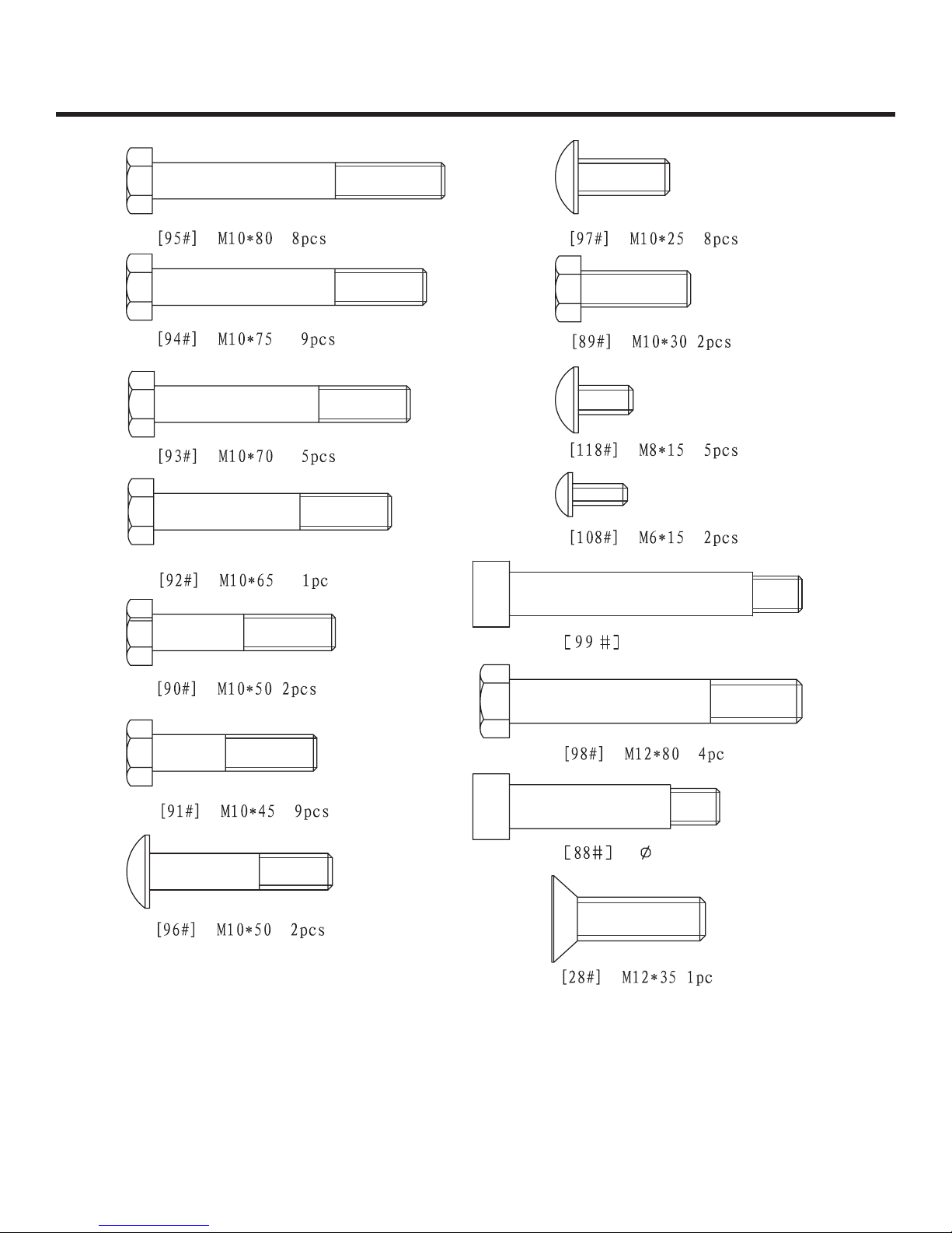
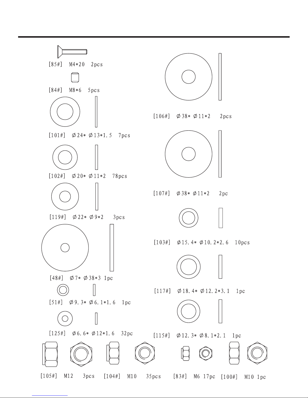
Assembly
8
12.2 * 69 1 pc
12.2 * 91.5 1 pc
Assembly
9
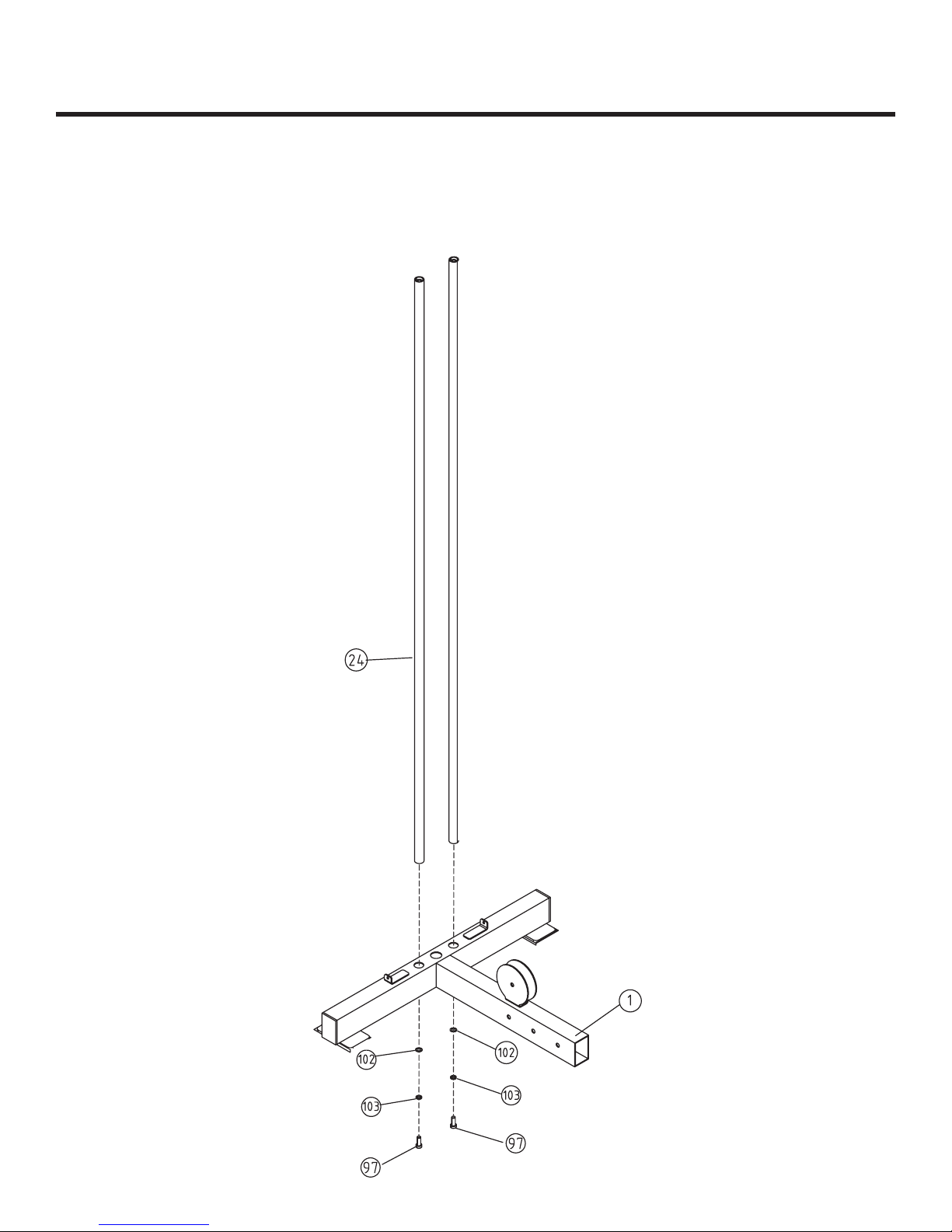
STEP 1
Insert the two Guide Rods (24) into Rear Base (1) and secure them in place using two
Washers (102), two Spring Washers (103), and two Allen Bolts (97).
Assembly
10
Figure 1

Assembly
11
STEP 2
Attach the Seat Pad Support Receptacle (2) to Rear Base (1) and secure in place using three
Nylon Locknuts (104), six Washers (102), and three Bolts (94).
Connect the Front Upright (86) to Seat Pad Support Receptacle (2) and secure together using
two Nylon Locknuts (104), four Washers (102), and two Bolts (95).
Insert the Pec Dec Mount (7) onto Seat Pad Support Receptacle (2) using two Nylon Locknuts
(104), four Washers (102), and two Bolts (94) on the side. Next, insert one Washer (107),
one Spring Washer (103), and one Bolt (93) through the top of the Seat Pad Receptacle (2).
Figure 2
Assembly
12
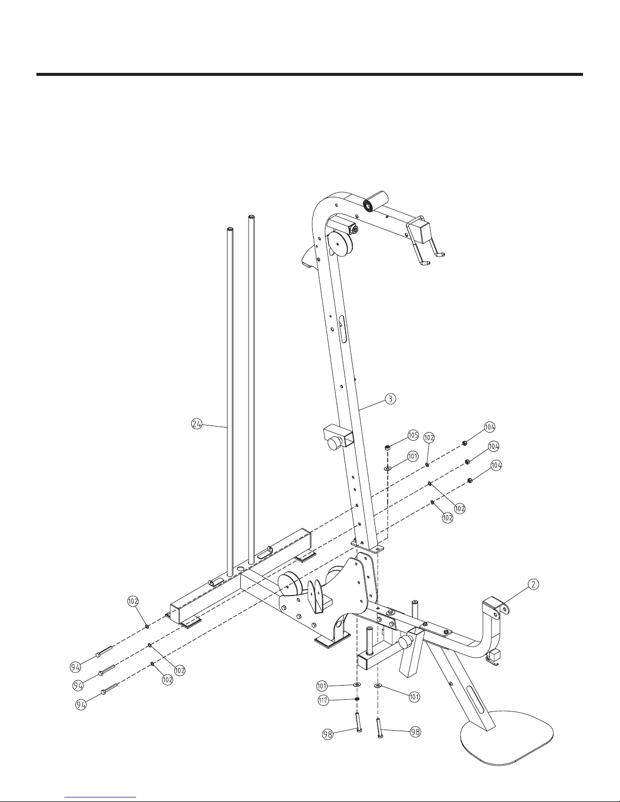
Step 3
Install the Main Upright (3) onto Seat Pad Support Receptacle (2). Secure it in place using
three Nylon Locknuts (104), six Washers (102), and three Bolts (94) on the side. Two Bolts
(98), one Spring Washer (117), three Washers (101), one Nylon Locknut (105) will secure it at
the bottom.
Figure 3
Assembly
13
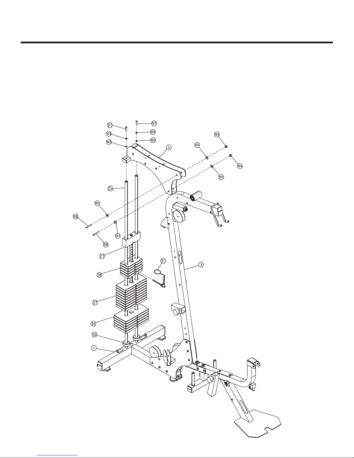
Step 4
Slide one Weight Stack Bumper (30) down each Guide Rod (24). Next, slide the weight
plates down the Guide Rods (24) in this order - five 15lb Plates (36), nine 10lb Plates (37), five
5lb Plates (38), and the Top Plate (27).
Insert the Main Top Beam (4) onto the two Guide Rods (24) and the Main Upright (3).
Secure Main Top Beam (4) to Main Upright (3) using two Nylon Locknuts (104), four Washers
(101), two Bolts (98). Last, use four Spring Washers (103) and two Allen Bolts (97) to secure
the Main Top Beam (4) to the two Guide Rods (24). Attach Weight Pin (31) to Weight Stack.
Figure 4

Step 5
Attach Press Arm Support (5) to Main Upright (3) by aligning the holes and sliding the Shaft
(74) through the holes of the Press Arm Support (5).
Secure the Shaft (74) to the Press Arm Support (5) using two Set Screws (84).
Install Press Arm (6) to Press Arm Support (5) by aligning the holes and sliding the Shaft
(73) through the holes of the Press Arm (6).
Secure the Shaft (73) to the Press Arm (6) using two Set Screws (84).
Assembly
14
Figure 5

Assembly
15
Step 6
Slide the Right Pec Dec Arm (8) on to the shaft of the Pec Dec Mount (7). Secure the arm in
place using one Big Washer (76), one Washer (102), one Spring Washer (103), and one Allen
Bolt (97).
Slide Pec Dec Handle Bar (19) onto the top of the Right Pec Dec Arm (8) and secure using
one Chrome Washer (106), one Washer (102), one Spring Washer (103), and one Allen Bolt
(97).
Repeat this step to complete the Left Pec Dec assembly.
Figure 6
Assembly
16
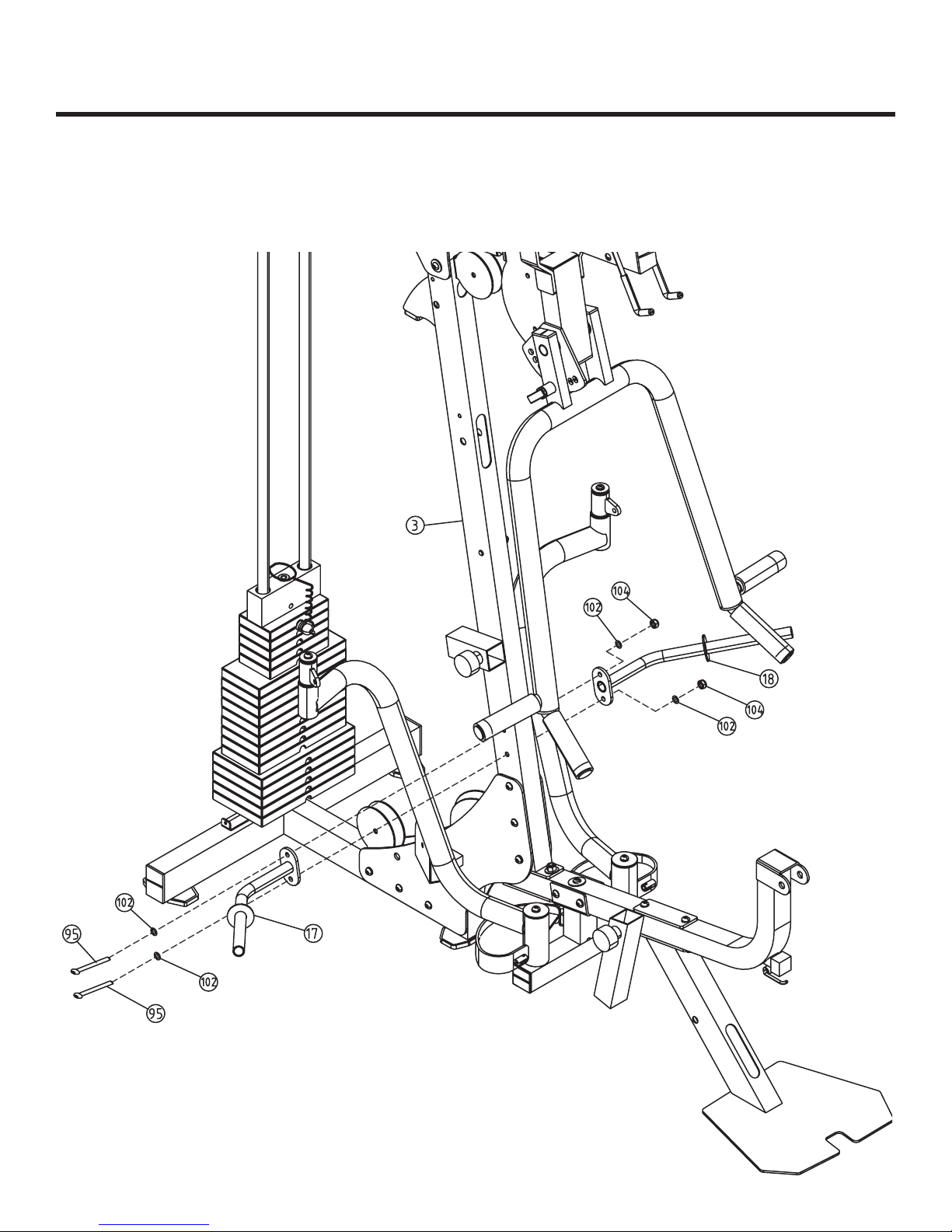
Step 7
Install the Right and Left Hold Leg Frames (17 & 18) to Main Upright (3) and secure using
two Nylon Locknuts (104), four Washers (102), and two Bolts (95).
Make sure both Hold Leg Frames are angled upwards.
Figure 7
Assembly
17
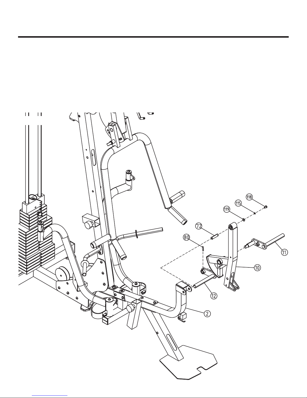
Step 8
Slide the Shaft (72) into the Leg Extension Lever (10). Attach Leg Extension Lever (10)
to Seat Pad Support Receptacle (2) and secure using one Washer (119), one Spring Washer
(115), and one Allen Bolt (118).
Slide Foam Frame w/ Shaft (11) through the Leg Extension Lever (10) and attach the Foam
Frame w/o Shaft (12) to the other side. Insert the Slip Tension Pin (80) through the hole
where the two foam frames meet. Note: You may need to use a rubber mallet to install Slip
Tension Pin (80).
Figure 8

Assembly
18
Step 9
Attach the Seat Pad (26) to the Seat Pad Support (13) using two Washers (102) and two Allen
Bolts (96). Slide the Seat Support assembly (13) into the Seat Pad Support Receptacle (2) and
secure by tightening attached Locking Knob.
Install the Telescope (14) to the bottom of the Back Pad Support (16) and secure in place
using one Nylon Locknut (104) and one Bolt (99).
Install the Tilting (15) to the top of the Back Pad Support (16) and secure in place using one
Nylon Locknut (104) and one Bolt (88).
Attach the Back Pad (25) to Back Pad Support (16) using two Washers (102) and two Bolts
(89).
Last, slide the Back Pad Support assembly into the receptacle on the Main Upright (3) and
secure by tightening the Locking Pop Pin (52).
Figure 9

Assembly
19
Step 10
Slide two Upholstered Roller Pads (42) onto Foam Frames (11 & 12) and secure using two Big
Plugs (65).
Slide the Long Foam Tube (77) through the hole in Seat Pad Support (13). Slide two Plastic
Washers (87) onto each end of Long Foam Tube (77). Next, slide two Upholstered Roller Pads
(42) onto each side of Long Foam Tube (77) and secure using two Big Plugs (65).
Slide two Upholstered Roller Pads (42) onto the Leg Hold Frames (17 & 18) and secure using
two Big Plugs (65).
Figure 10
Assembly
20
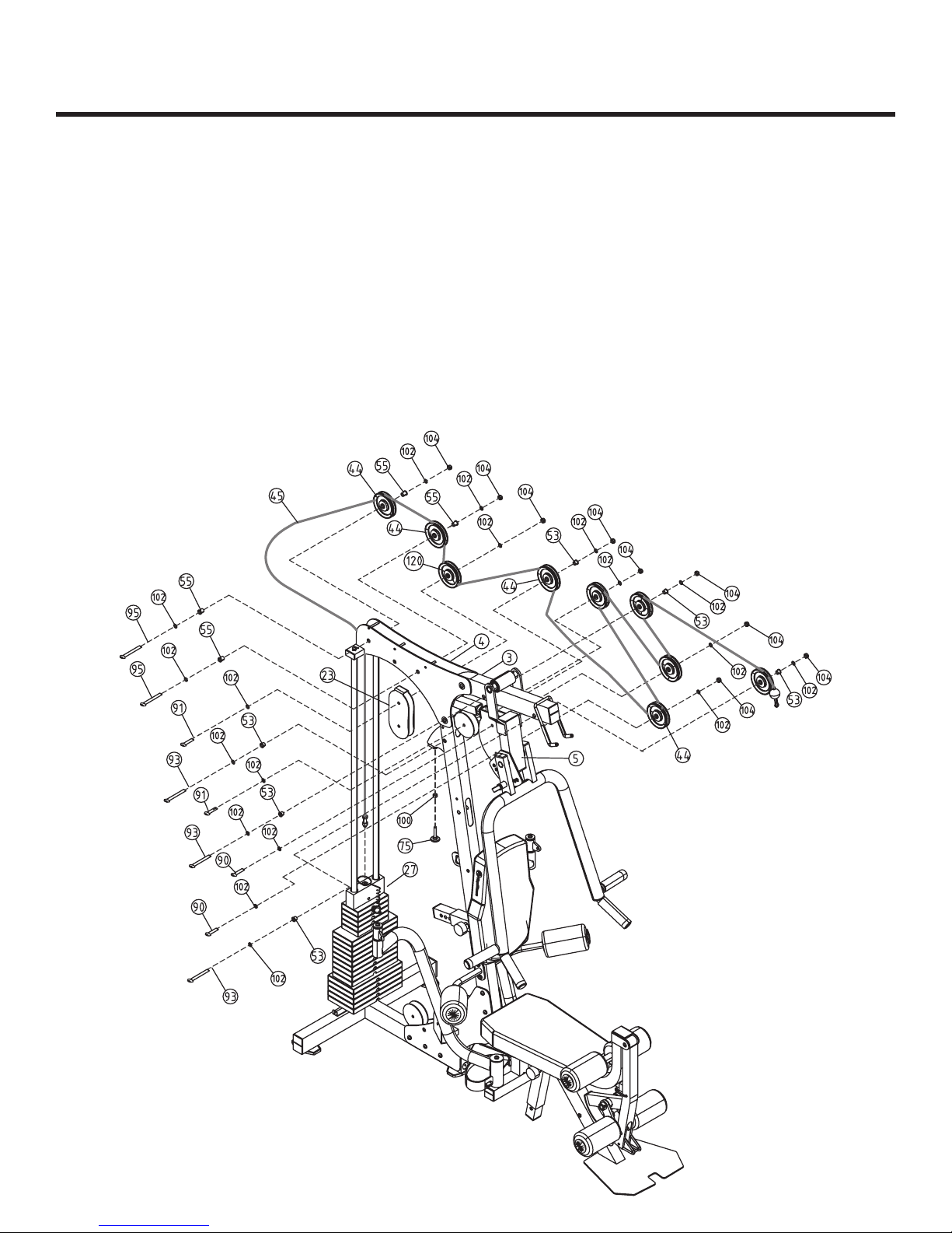
Step 11
Note: Stretch all cables out completely and make sure all twisting is removed before installing.
Install Chest Press Cable (45) as detailed in Figure 11. Follow dotted lines to identify exact
location of pulleys. See Page 29 “Cable View” for more detail.
Start by threading cable end into Top Plate (27).
You will need the following for installation:
Pulley (44) - Qty. 8
Cable (45) - Qty. 1
Nylon Locknut (104) - Qty. 9
Long Pulley Spacer (53) - Qty. 6
Longer Pulley Spacer (55) - Qty. 4
Adjustable Stopper (75) - Qty. 1
Bolt (90) - Qty. 2
Bolt (91) - Qty. 2
Bolt (93) - Qty 3
Bolt (95) - Qty. 2
Washer (102) - Qty. 18
Hex Nut (100) - Qty. 1
Figure 11
Small Pulley (120) - Qty. 1
Table of contents


