Vitech VT-MM-3K6-AU User manual

On Grid/Off Grid Multi-Mode Inverter
VT-MM-3K6-AU VT-MM-5K-AU VT-MM-8K-AU
User Manual and Installation Guide
<KX 212008
ViTech Power Australia
Add: 5/364 Park Road, Regents Park, NSW 2075
Tel: 1300 699 669

33-35
36-38
39
40
42
01
01-04
04-17
18
19-33
Contents
1. Safety Introductions
2. Product instructions
od ee
od ee
e ee
3. Installation
Mo o
e oeo
oeo
oeo
6 oeo
oeodo
oeo
e o ee
e e e oeo d
ee e e ee
4. OPERATION
oe
eo d e
5. LCD Display Icons
M ee
o oe e
e eo & od & d
e e Me
e Me
6 e e Me
e o Mode e Me
d e Me
eeo o e e Me
ded o e Me
ee o e Me
6. Mode
7. Inverter Commissioning
8. Fault information and processing
9. Limitation of Liability
10. Datasheet
11. Appendix I
12. Appendix II
35
41
1. Safety Introductions
This chapter contains important safety and operating instructions. Read and keep this
manual for future reference.
Before using the inverter, please read the instructions and warning signs of the battery and
corresponding sections in the instruction manual.
Do not disassemble the inverter. If you need maintenance or repair, take it to a professional
service center.
Improper reassembly may result in electric shock or fire.
To reduce risk of electric shock, disconnect all wires before attempting any maintenance or
cleaning. Turning off the unit will not reduce this risk.
Caution: Only qualified personnel can install this device with battery.
Never charge a frozen battery.
For optimum operation of this inverter, please follow required specification to select
appropriate cable size. It is very important to correctly operate this inverter.
Be very cautious when working with metal tools on or around batteries. Dropping a tool
may cause a spark or short circuit in batteries or other electrical parts,even cause an
explosion.
Please strictly follow installation procedure when you want to disconnect AC or DC
terminals. Please refer to ”Installation” section of this manual for the details. Grounding
instructions - this inverter should be connected to a permanent grounded wiring system.
Be sure to comply with local requirements and regulation to install this inverter.
Never cause AC output and DC input short circuited. Do not connect to the mains when
DC input short circuits.
2. Product Introduction
This is a multi-functional inverter,combining functions of inverter, solar charger and
battery charger to offer uninterpretable power support with portable size. Its
comprehensive LCD display offers user configurable and easy accessible button operation
such as battery charging ,AC/solar charging, and acceptable input voltage based on
different applications.
- 01 -

2.1 Product Overview
1: Inverter Indicators
2: LCD display
3: Function Buttons
4: Battery input connectors
5: RS 485 Port
6: CAN Port
7: DRMs Port
8: Parallel port
9: Function Port
10: Generator input 16: WiFi Interface
11: Load
12: Grid
13: Power on/off button
14: DC Switch
15: PV input with two MPPT
1
2
5
9
10
11
12
14
15
16
13
7
6
3
4
8
- 02 -
2.2 Product Features
2.3 Basic System Architecture
- 220V Single phase Pure sine wave inverter.
- Self-consumption and feed-in to the grid.
- Auto restart while AC is recovering.
- Programmable supply priority for battery or grid.
- Programmable multiple operation modes:On grid,off grid and UPS.
- Configurable battery charging current/voltage based on applications by LCD setting.
- Configurable AC/Solar/Generator Charger priority by LCD setting.
- Compatible with mains voltage or generator power.
- Overload/over temperature/short circuit protection.
- Smart battery charger design for optimized battery performance
- With limit function,prevent excess power overflow to the grid.
- Supporting WIFI monitoring and build-in 2 strings of MPP trackers
- Smart settable three stages MPPT charging for optimized battery performance.
- Time of use function.
- Smart Load Function.
- Parallel function On-Grid&Off-Grid.
The following illustration shows basic application of this inverter.
It also includes following devices to have a Complete running system.
-Generator or Utility
-PV modules
Consult with your system integrator for other possible system architectures depending on your
requirements.
This inverter can power all kinds of appliances in home or office environment, including motor
type appliances such as refrigerator and air conditioner.
-03 -

o
e e ee eoe o ee e e o ded e
e Yo od e eeed e e e oo e
o eo
ViTech Power On/Off Grid d ee
e ee o e M6
e ee eo o M
e
6
GridBackup Load
WiFI
GPRS
phoneCloud services
On-Grid Home Load
Generator
ATS
Grid-connected InverterSmart Load
CT
Battery
SolarWind
CT
AC cable DC cable
Grid-connected Inverter
Cloud services

Considering the following points before selecting where to install:
Please select a vertical wall with load-bearing capacity for installation, suitable for
installation on concrete or other non-flammable surfaces,installation is shown below.
Install this inverter at eye level in order to allow the LCD display to be read at all times.
Chart 3-1 Parts List
3.2 Mounting instructions
Installation Precaution
This hybrid inverter is designed for outdoor use(IP65),Please make sure the installation
site meets below conditions:
- Not in direct sunlight
- Not in areas where highly flammable materials are stored.
- Not in potential explosive areas.
- Not in the cool air directly.
- Not near the television Antenna or antenna cable.
- Not higher than altitude of about 2000 meters above sea level.
- Not in environment of precipitation or humidity(>95%)
Please AVOID direct sunlight, rain exposure, snow laying up during installation and
operation. Before connecting all wires,please take off the metal cover by removing
screws as shown below:
6
7
8
9
Current transformer (Optional)
Battery sensor
L-type hexagon wrench
Wall mounting bracket
1
1
1
1
-05 -
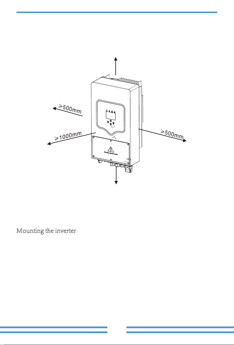
The ambient temperature should be between -25~60℃ to ensure optimal operation. Be
sure to keep other objects and surfaces as shown in the diagram to guarantee sufficient
heat dissipation and have enough space for removing wires.
≥500mm
≥500mm
For proper air circulation to dissipate heat, allow a clearance of approx. 50cm to the side
and approx.50cm above and below the unit.And 100cm to the front.
Mounting the inverter
Inverter should vertically installed, as shown installation procedure show below:
1. Position the bolts on the appropriate wall according to the bolt positions on the
mounting shelves and mark the holes. On the brick wall, the installation must be
suitable for the expansion bolt installation.
2. Ensure that the position of the installation holes on the wall (A, B, C, D) are the
same position of the install plate, and the mounting level is guaranteed.
3. Hang the inverter to the top of the mounting rack and then use the M4 screw in the
accessory to lock E and F to ensure that the inverter does not move.
-06 -
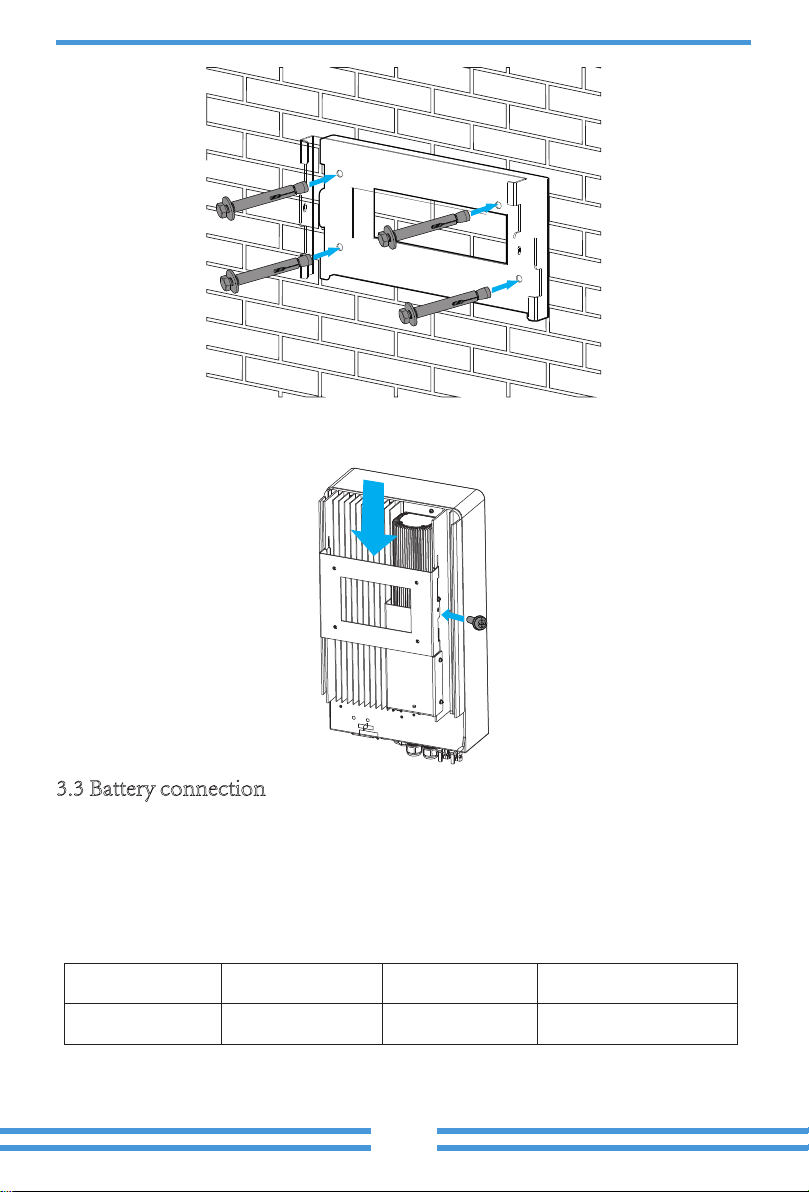
Chart 3-2 Cable Size
3.3 Battery connection
For safe operation and compliance, a separate DC over-current protector or disconnect
device is required between the battery and the inverter. In some applications, switching
devices may not be required but over-current protectors are still required. Refer to the
typical amperage in the table below for the required fuse or circuit breaker size.
Model
3.6/5KW
Wire Size
3AWG
Cable(mm )
2
25
Torque value max
5.2Nm
Inverter hanging plate installation
-07 -

All wiring must be performed by a professional person.
Connecting the battery with a suitable cable is important for safe and
efficient operation of the system. To reduce the risk of injury, refer to
Chart 3-2 for recommended cables.
Please follow below steps to implement battery connection:
1. Please choose a suitable battery cable with correct connector which can well fit into the
battery terminals. 2. Use a suitable screwdriver to unscrew the bolts and fit the battery
connectors in,then fasten the bolt by the screwdriver,make sure the bolts are tightened
with torque of 5.2 N.M.
2. Nm in clockwise direction,make sure polarity at both the battery and inverter is correctly
connected.
3. In case of children touch or insects go into the inverter,Please make sure the inverter
connector is fasten to waterproof position by twist it clockwise.
Installation must be performed with care.
Before making the final DC connection or closing DC breaker/
disconnect,be sure positive(+) must be connect to positive(+)
and negative(-) must be connected to negative(-). Reverse polarity
connection on battery will damage the inverter.
-08 -
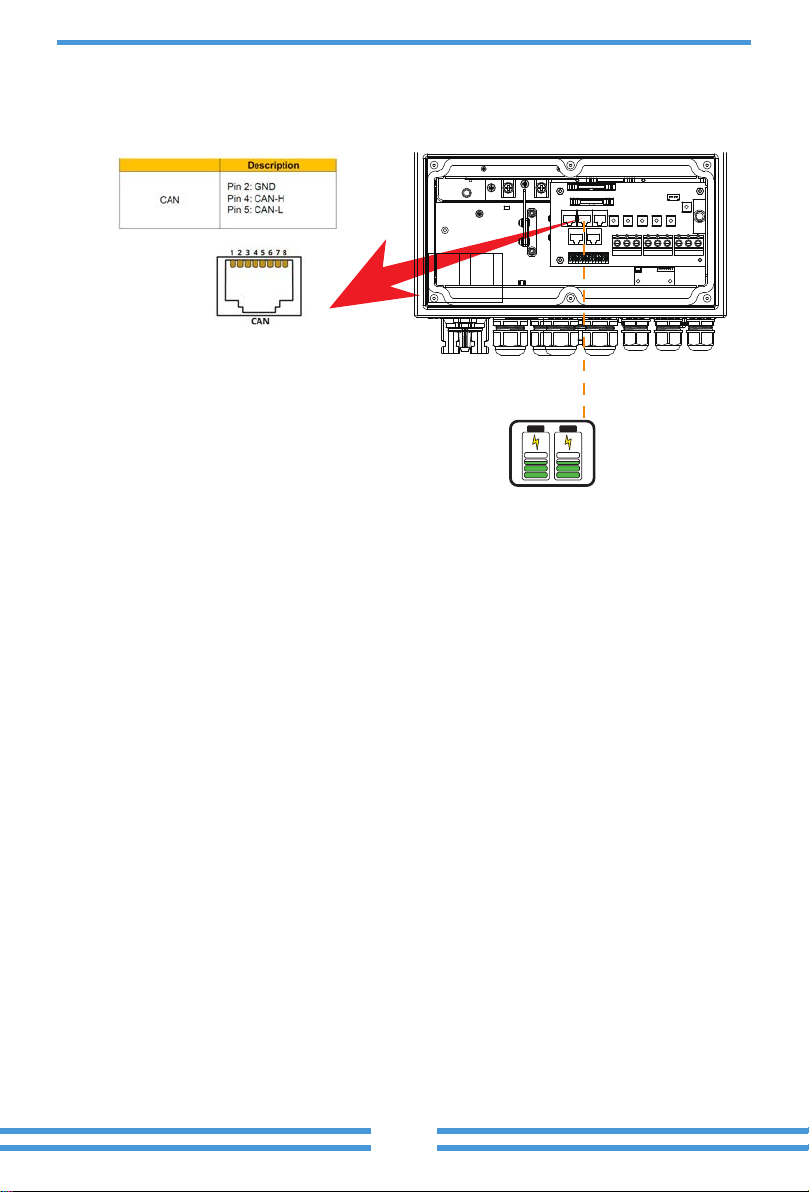
Lithium battery can be managed and monitored by Vitech Power Inverter through CAN
port.
The installer should follow the Vitech Power CAN port PIN description to ensure the
communication cable is made correctly to realize the CAN communication between lithium
battery BMS and inverter.
- 09 -
3.3.1 Lithium Battery BMS connection
Battery
BMS CAN Port

e eee oeo
e

3.4 AC Input/Output Connection
Before connecting to AC input power source,please install a separate AC breaker between
inverter and AC input power source. This will ensure the inverter can be securely
disconnected during maintenance and fully protected from over current of AC input. The
recommended of AC breaker is 25A for 3.6kw and 32A for 5KW.
There are three terminal blocks with “Grid”“Load”and “GEN”markings. Please
do not misconnect input and output connectors.
1. Before making AC input/output connection,be sure to open DC protector or
disconnector first.
2. Remove insulation sleeve 10mm length,unscrew the bolts,insert the AC input wires
according to polarities indicated on the terminal block and tighten the terminal screws.
Make sure the connection is complete.
All wiring must be performed by a qualified personnel.It is very important
for system safety and efficient operation to use appropriate cable for AC
input connection. To reduce risk of injury,please use the proper
recommended cable as below.
Chart 3-3 Recommended Size for AC wires
Please follow below steps to implement AC input/output connection:
3.6KW
Model
5KW
12AWG
Wire Size
10AWG
4
6
1.2Nm
1.2Nm
Cable(mm )
2Torque value
NGrid
Load
GEN PORT
LPE
- 11 -
ee o e od o oe ded o e e o d
e e e e o oe oeod e d e o eed
e e
Me e e e e ee oeed
e odoe e eed e e o e ee
eed o e eo e o e ee de o oe
oe o d eoe o e e de o o oeed
eo ee d o deee e e o odoe
eed ede o eoe oee ee
e oeod d o o o oe o e oee
e e de o e odoe
oeo
eoe oe o odeee ee ee eee
ee d ode e o o e e d ee oeo
o e oe e o ode oeo o ede o ee e
e oe eoeded e ze eo
e e oe oe doeed eoe e o e o
e
o od o do o oe ode oe
e ee o e ee o ee oded ode
e e ee o e ee e ode ee e
e od
Mode
6
e ze
e
2
Chart 3-4 Cable size
Mode eeo
e ee oe ode ee e e o ode eo ee
e oe o o ode o eeed oe
oe o ee
e oe o o ode od e e oe
eeed o e o o e oeo ee
e de o ee e o o ode
eoe e ee o oe o e d e ee dee e ede
o o od d e ede o o od o ee ede
e e Ω he ee o oe o e d d eo eo
o
oe
ee Mode 6
dd M oe e
o o M e
o o e M e
3
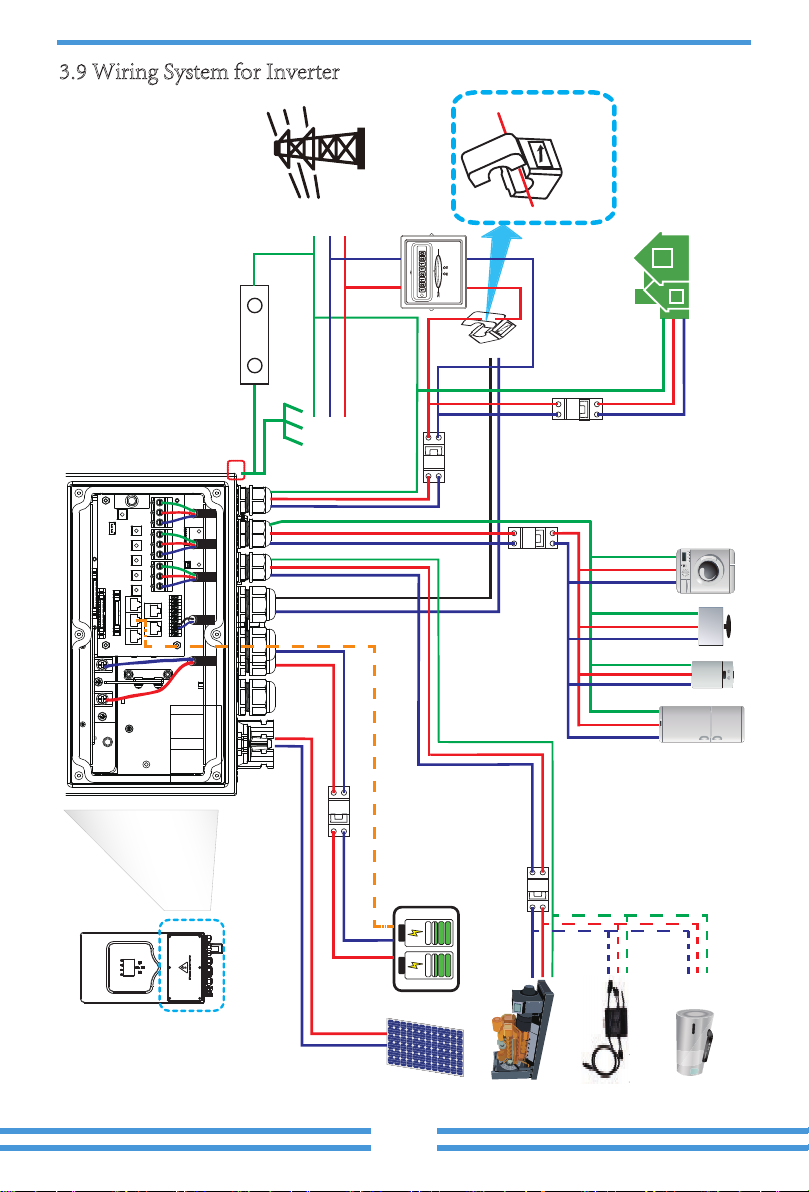
6 oeo
oeodo
od e e oeed o od e o d de ee ee o
e o oee odo
e e
ee
e
d
4
oeo
o setupee ee o
ViTech Power Inverter WiFi sticker manual
.
5
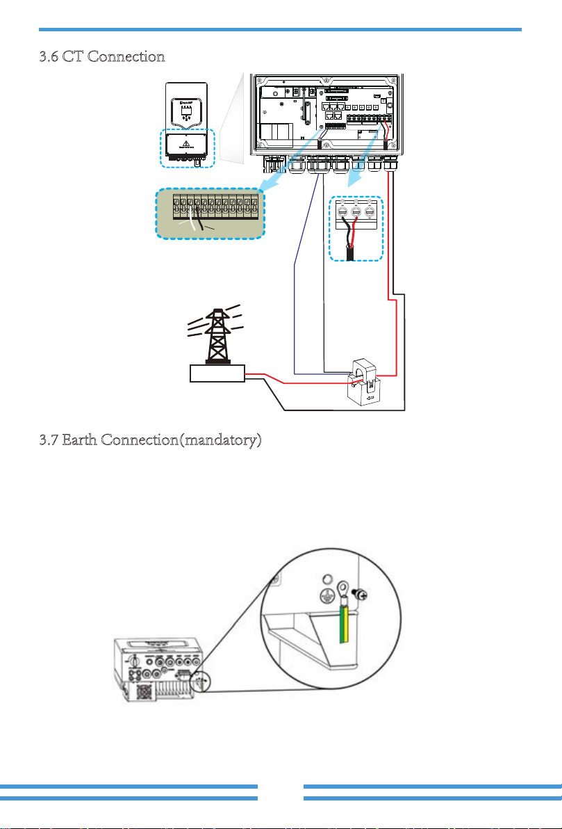
3.7.1 Earth Fault Detection and Alarm
e oe ee oe 6 M do
o ee oe d e e ee e oo
o oe o eoe oo
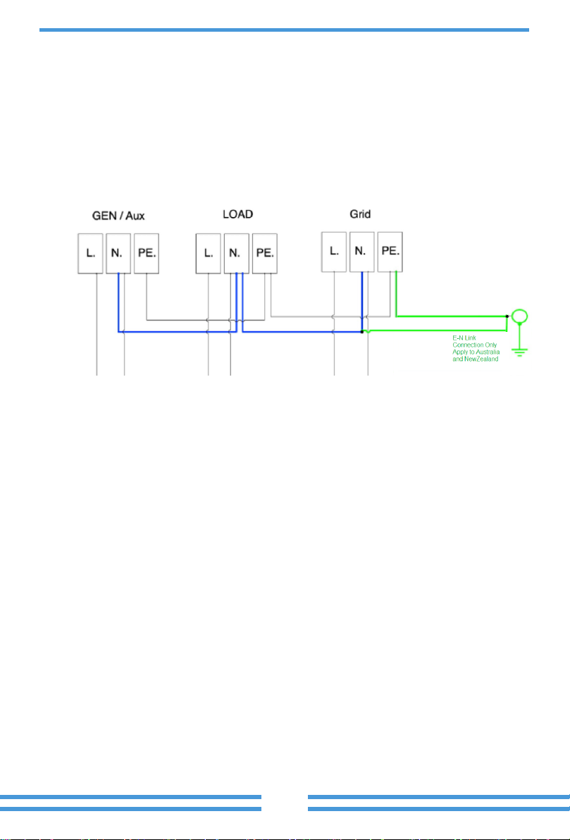
3.7.2 Neutral Continuity between EPS and Grid
According to Australian safety requirement, for grid-tied applications, the neutral
cable of grid side and EPS load side must be connected together, otherwise EPS load
function will not work properly.
For Australia and New Zealand safety requirement, the E-N link connection must be
applied between the neutral and protection earth for both off-grid and on-grid
applications.
For other market, neutral and protection earth are not be linked. E-N link should not
be applied.
e o ee
e
o
ee
ee
ee
ee
ee
eeo
Moee
od
o o
o d
ee
o
o
Loads
Loads
Grid
Moee
Ground
6
M o
7
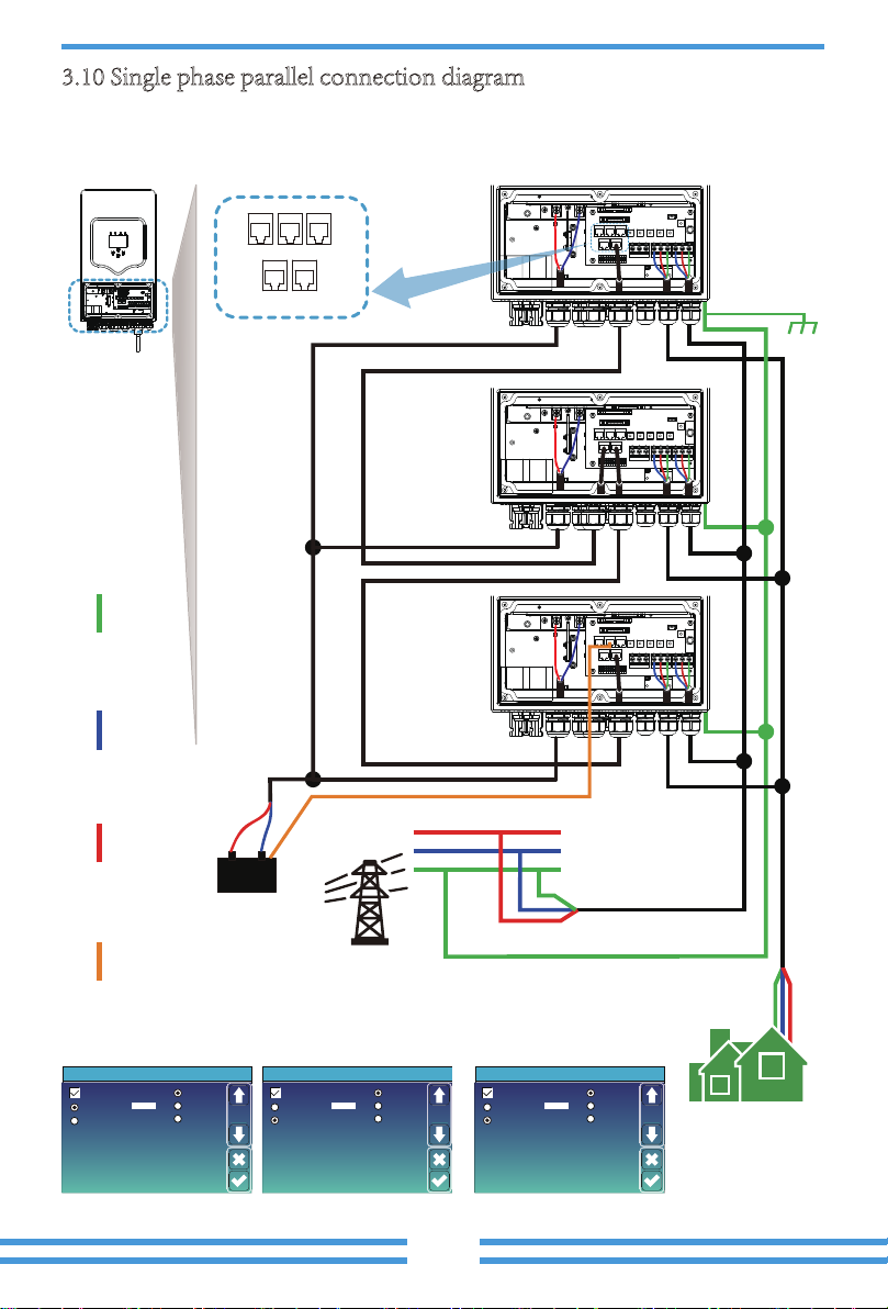
e e e
e e e oeo d
Parallel
Master
Slave
Modbus SN
01
A Phase
B Phase
C Phase
Advanced Function
Paral.
Set3
Parallel
Master
Slave
Modbus SN
02
A Phase
B Phase
C Phase
Advanced Function
Paral.
Set3
Parallel
Master
Slave
Modbus SN
03
A Phase
B Phase
C Phase
Advanced Function
Paral.
Set3
Me ee e ee e ee
M M M
e e
d
od
ee
ee
o
e
od
ee
o
e
ee
o
e
e
e M ee

4. OPERATION
4.1 Power ON/OFF
Once the unit has been properly installed and the batteries are connected well,simply press
On/Off button(located on the left side of the case) to turn on the unit.When system without
battery connected,but connect with either PV or grid,and ON/OFF button is switched off,
LCD will still light up(Display will show OFF),In this condition,when switch on ON/OFF
button and select NO battery,system can still working.
To turn off the solar system, first turn off the solar main switch in the meter box. Then
turnoff the AC isolator at the inverter. Step3 is to turn off the PV DC isolator and the battery
DC isolator. At last, switch off the ON/OFF button of the inverter. After about 10 sec, the
inverter as well as the whole system will shutdown.
4.2 Operation and Display Panel
The operation and display panel,shown in below chart,is on the front panel of the inverter. It
includes four indicators,four function keys and a LCD display,indicating the operating
status and input/output power information.
Chart 4-1 LED indicators
LED Indicator
DC
AC
Normal
Alarm
Green led solid light
Green led solid light
Green led solid light
Red led solid light
PV Connection normal
Grid Connection normal
Inverter operating normal
Malfunction or warning
Messages
Chart 4-2 Function Buttons
Function Key
Esc
Up
Down
Enter
Description
To exit setting mode
To go to previous selection
To go to next selection
To confirm the selection
- 18 -
This manual suits for next models
2
Table of contents
Popular Inverter manuals by other brands


Northern Lights
Northern Lights L944D, M944W, NL944D2, M30CW, M944T, NL944T2, and... Operator's manual

Delta Energy Systems
Delta Energy Systems Solivia 3.6 EU G4 TR Operation and installation manual

Kaco
Kaco blueplanet 3.0 NX1 M2 Quick Installation Instruction

Hitachi
Hitachi UTOPIA RASC Series Installation and operation manual

Makita
Makita G SERIES Instructions for use

PrimeVOLT
PrimeVOLT PV 7KTL-D1P user manual