manuals.online logo
Brands
  1. Home
  2. •
  3. Brands
  4. •
  5. ABB
  6. •
  7. Inverter
  8. •
  9. ABB UNO-2.0-I-OUTD User manual

ABB UNO-2.0-I-OUTD User manual

In addition to what is explained below, the safety and installation information provided in the
installation manual must be read and followed. The technical documentation and the interface
and management software for the product are available at the website.
The device must be used in the manner described in the manual. If this is not the case the
safety devices guaranteed by the inverter might be ineffective.
Quick Installation Guide
UNO-2.0/2.5-I-OUTD
ABB Solar inverters
1.
Labels and SymbolsInverter Models and Components
2.
Instruments
4.
Choice of installation location
EN
Assembly Instruction
7.
Lifting and transport
5.
Opening the cover
8.
Choice of installation location
3.
List of supplied components
6.
7KHODEHOVRQWKHLQYHUWHUKDYHWKH$JHQF\PDUNLQJPDLQWHFKQLFDOGDWDDQGLGHQWL¿FDWLRQRIWKHHTXLSPHQWDQGPDQXIDFWXUHU
V
dc max
I
dc max
V
dc MPP
V
dc, Full Power
I
sc max
V
acr
f
r
I
ac max
P
acr (cos
Ĵ
=1)
MODEL:
UNO-2.5-I-OUTD-X
IP65
5minutes
520 V
90 - 520 V
12.8 A
200 - 470 V
15 A
Made in Italy
DIN V VDE 0126-1-1
PROTECTIVE CLASS: I
230 V 1Ø
50 Hz
12.5 A
2500 W @ 45°C amb.
-25 to +60 °C
-13 to +140 °F
SOLAR INVERTER
www.abb.com/solar
V
dc max
I
dc max
V
dc MPP
V
dc, Full Power
I
sc max
V
acr
f
r
I
ac max
P
acr (cos
Ĵ
=1)
MODEL:
UNO-2.0-I-OUTD-S
IP65
5minutes
520 V
90 - 520 V
12.5 A
200 - 470 V
15 A
Made in Italy
DIN V VDE 0126-1-1
PROTECTIVE CLASS: I
230 V 1Ø
50 Hz
10.5 A
2000 W @ 50°C amb.
-25 to +60 °C
-13 to +140 °F
SOLAR INVERTER
www.abb.com/solar
The labels attached to the equipment must NOT be removed, damaged, dirtied, hidden,etc...
,IWKHVHUYLFHSDVVZRUGLVUHTXHVWHGWKH¿HOGWREHXVHGLVWKHVHULDOQXPEHU61<<::666666
,QWKHPDQXDODQGRULQVRPHFDVHVRQWKHHTXLSPHQWWKHGDQJHURUKD]DUG]RQHVDUHLQGLFDWHGZLWKVLJQVODEHOVV\PEROVRULFRQV
Always refer to instruction
manual General warning - Important
safety information +D]DUGRXVYROWDJH Hot surfaces
IP65
Protection rating of
HTXLSPHQW Temperature range With isolation
transformer Direct and alternating
currents, respectively
Positive pole and negative
pole of the input voltage
(DC)
Always use safety clothing
and/or personal safety
devices
Point of connection for
grounding protection Time need to discharge
stored energy
5
01
Inverter model
02
Inverter Part Number
03
Inverter Serial Number
04
Week/Year of manufacture
UNO-X.X-I-OUTD-Y
P/N:PPPPPPPPPPP
WO:XXXXXXX
SO:SXXXXXXXX Q1
SN:YYWWSSSSSS WK:WWYY
01
02
04
03
Transport and handling
7UDQVSRUWRIWKHHTXLSPHQWHVSHFLDOO\E\URDGPXVWEHFDUULHGRXWZLWKE\VXLWDEOHZD\VDQGPHDQVIRUSUR-
tecting the components from violent shocks, humidity, vibration, etc.
Lifting
7KHPHDQVXVHGIRUOLIWLQJPXVWEHVXLWDEOHWREHDUWKHZHLJKWRIWKHHTXLSPHQW
Unpacking and checking
The components of the packaging must be disposed on in accordance with the regulations in force in the
country of installation.
:KHQ\RXRSHQWKHSDFNDJHFKHFNWKDWWKHHTXLSPHQWLVXQGDPDJHGDQGPDNHVXUHDOOWKHFRPSRQHQWVDUH
SUHVHQW,I\RX¿QGDQ\GHIHFWVRUGDPDJHVWRSXQSDFNLQJDQGFRQVXOWWKHFDUULHUDQGDOVRSURPSWO\LQIRUPWKH
Service ABB.
Equipment weight
Model Mass weight Lifting points n°#
UNO-2.0-I-OUTD
UNO-2.0-I-OUTD-S UNO-2.5-I-OUTD
UNO-2.5-I-OUTD-S 17 Kg 2
UNO
Environmental checks
- Consult the technical data to check the environmental parameters to be observed
- Installation of the unit in a location exposed to direct sunlight must be avoided as it may cause:
1. power limitation phenomena in the inverter (with a resulting decreased energy production by the system)
2. premature wear of the electrical/electromechanical components
3. premature wear of the mechanical components (gaskets) and of the user interface (display)
- Do not install in small closed rooms where air cannot circulate freely
- 7RDYRLGRYHUKHDWLQJDOZD\VPDNHVXUHWKHÀRZRIDLUDURXQGWKHLQYHUWHULVQRWEORFNHG
- 'RQRWLQVWDOOLQSODFHVZKHUHJDVHVRUÀDPPDEOHVXEVWDQFHVPD\EHSUHVHQW
- Do not install in rooms where people live or where the prolonged presence of people or animals is expected, because of
the noise (about 50dB(A) at 1 m) that the inverter makes during operation
- $YRLGHOHFWURPDJQHWLFLQWHUIHUHQFHWKDWFDQFRPSURPLVHWKHFRUUHFWRSHUDWLRQRIHOHFWURQLFHTXLSPHQWZLWKFRQVHTXHQW
situations of danger.
Installations above 2000 metres
2QDFFRXQWRIWKHUDUHIDFWLRQRIWKHDLUDWKLJKDOWLWXGHVSDUWLFXODUFRQGLWLRQVPD\RFFXU
- /HVVHI¿FLHQWFRROLQJDQGWKHUHIRUHDJUHDWHUOLNHOLKRRGRIWKHGHYLFHJRLQJLQWRGHUDWLQJEHFDXVHRIKLJKLQWHUQDO
temperatures
- Reduction in the dielectric resistance of the air that, in the presence of high operating voltages (DC input), can create
electric arcs (discharges) that can reach the point of damaging the inverter
All installations at altitudes of over 2000 metres must be assessed case by case with the ABB Service department.
Installation position
- Install on a wall or strong structure suitable for bearing the weight
- Install in safe, easy to reach places
- If possible, install at eye-level so that the display and status LEDs can be seen easily
- ,QVWDOODWDKHLJKWWKDWFRQVLGHUVWKHKHDYLQHVVRIWKHHTXLSPHQW
- Install vertically with a maximum inclination of +/- 5°
- 7RFDUU\RXWPDLQWHQDQFHRIWKHKDUGZDUHDQGVRIWZDUHRIWKHHTXLSPHQWUHPRYHWKHFRYHUV
on the front. Check that there are the correct safety distances for the installation that will allow
the normal control and maintenance operations to be carried out
- Comply with the indicated minimum distances
- For a multiple installation, position the inverters side by side
- If the space available does not allow this arrangement, position the inverters in a staggered
DUUDQJHPHQWDVVKRZQLQWKH¿JXUHVRWKDWKHDWGLVVLSDWLRQLVQRWDIIHFWHGE\RWKHULQYHUWHUV
Final installation of the inverter must not compromise access to any disconnection
devices that may be located externally.
Please refer to the warranty terms and conditions available on the website and evaluate
any possible exclusion due to improper installation.
UNO UNO UNO
UNO UNO
UNO UNO
UNO UNO
UNO UNO
35
cm
50
cm
15cm 15cm
UNO
UNO
The models of inverter to which this guide refers are available in 2 power ratings:
2.0 kW / 2.5 kW.
)RULQYHUWHUVRIHTXDORXWSXWSRZHUWKHYDULDQWEHWZHHQWKHYDULRXVPRGHOVLVWKH
presence or lack thereof, of the DC disconnect switch
07
.
812,287' 812,287'6
- Number of input channels: 1
- DC disconnect switch
07
: No
- ,QSXWFRQQHFWRUVTXLFN¿WFRQQHF-
tors (2 pairs)
- Number of input channels: 1
- DC disconnect switch
07
: Yes
- ,QSXWFRQQHFWRUVTXLFN¿WFRQQHF-
tors (2 pairs)
812,287' 812,287'6
- Number of input channels: 1
- DC disconnect switch
07
: No
- ,QSXWFRQQHFWRUVTXLFN¿WFRQQHF-
tors (2 pairs)
- Number of input channels: 1
- DC disconnect switch
07
: Yes
- ,QSXWFRQQHFWRUVTXLFN¿WFRQQHF-
tors (2 pairs)
Main components
01
Bracket
09
AC output screw terminal block
02
Inverter
10
DC input connectors
03
Locking screw
11
Anticondensation valve
04
Front cover
12
Display
05
Main board
13
Keypad
06
Service cable glands
14
LED panel
07
DC disconnect switch
15
Heat sink
08
AC cable gland
UNO
01
02
03
05
14
12
13
15
09
06
04
07
10
11
08
:DOO3ROHPRXQWLQJ
'XULQJLQVWDOODWLRQGRQRWSODFHWKHLQYHUWHU
02
with the front cover
04
facing towards the
ground.
- Position the bracket
01
perfectly level on the wall
and use it as a drilling template.
- 'ULOOWKHKROHVUHTXLUHGXVLQJDGULOOZLWKPPELW
The holes must be about 70mm deep.
- On bracket
01
there are 5 fastening holes, but only
3 are used depending on the type of installation: on
a pole holes A, on a wall holes B.
- Fix the bracket to the wall with the 3 wall anchors,
10mm in diameter, supplied.
- Hook the inverter to the bracket by inserting the
head of the rear screws in the slots as shown in
WKH¿JXUH
- Proceed to anchor the inverter to the bracket by
tightening the locking screw
03
located on the
lower side.
- Unscrew the 4 screws and open the front cover
04
upwards in order to make all the necessary
connections.
7KHFRYHULVHTXLSSHGZLWK¿[HGKLQJHVDQG
cannot be removed.
- Once the connections have been made proceed
to closing the cover by tightening the 4 screws
RQWKHIURQWWRWKHWRUTXHLQGLFDWHGLQWKHVSHF-
L¿FDWLRQV
- 5HPRYHWKHSURWHFWLYH¿OPORFDWHGRQWKHIURQW
UNO
A
10
11
01
03
04
08 06
09
05
A
B
02
15
B
BA
13
12
14
3 x
Ø
10 mm
Main Components
01
Bracket
02
Inverter
03
Locking screw
04
Front cover
05
Main board
06
Service cable glands
07
DC disconnect switch
08
AC cable gland
09
AC output screw terminal block
10
DC input connectors
11
Anticondensation valve
12
Display
13
Keypad
14
LED panel
15
Heat sink
21 3 4 5
Opening the front cover is assisted by 2 hinges on both the inner sides of
the inverter, and it can be carried out with ease following the procedure
described below:
-Slacken the 4 screws fastening the front cover
04
(step 1)
-Open the cover by pulling it toward you and then pushing it upwards on
both sides (steps 2 and 3).
-Lock the cover in place by pushing it forwards (steps 4 and 5)
/('VDQG%877216, in various combinations, can be used to view the status or carry out complex actions that are described more fully in the manual.
32:(5
/('
*5((1On if the inverter is
working correctly. Flashes when
checking the grid or if there is
LQVXI¿FLHQWVXQOLJKW
$/$50
/('
<(//2:The inverter has de-
tected an anomaly. The anomaly is
shown on the display.
*),/('
5('Ground fault on the DC side
of the PV generator.The error is
shown on the display.
7KHRSHUDWLQJSDUDPHWHUVRIWKHHTXLSPHQWDUHGLVSOD\HGWKURXJKWKHGLVSOD\
12
: warnings, alarms, channels, voltages, etc.
Description of V\PEROVDQGGLVSOD\¿HOGV
b1 RS485 data transmission b13 Daily energy produced
b2 RS485 line present b14 PV voltage > Vstart
b3 Radio line present. b15 DC voltage value
b4 Bluetooth line present (*) b16 DC current value
b5 WiFi line present (*) b17 DC/DC circuit part
b6 Warning b18 DC/AC circuit part
b7 Temperature derating b19 AC voltage value
b8 Instantaneous power b20 AC current value
b9 MPP scan running b21 Connection to the grid
b10 Graphic display b22 Grid status
b11 Power graph b23 Cyclic view on/off
b12 Total energy (*) NOT available
DC
AC
b1 b2 b3b4 b6
b7 b9 b10 b17
b16
b14
b13
b12
b11 b15 b18
b20 b22
b21
b19 b23
b8
b5
POWER ALARM GFI ESC UP DOWN ENTER
DC
AC
14 12 13
ESC It is used to access the main menu, to go
back to the previous menu or to go back
to the previous digit to be edited.
UP It is used to scroll up the menu options or to
shift the numerical scale in ascending order.
'2:1
It is used to scroll down the menu options
or to shift the numerical scale in descending
order.
(17(5
It can be used to conrm an action, to access
the submenu for the selected option (indica-
ted by the > symbol) or to switch to the next
digit to be edited.
Components available for all models Quantity
&RQQHFWRUIRUFRQQHFWLQJWKHFRQ¿JX-
rable relay 2
Connector for the connection of the
communication and control signals 2
L-key, TORX TX20 1
)HPDOHTXLFN¿WFRQQHFWRUV 2
0DOHTXLFN¿WFRQQHFWRUV 2
Bracket and screws for lead sealing the
AC connector 1
Components available for all models Quantity
Two-hole gasket for M20 signal cable
glands and cover 2 + 2
Bracket for wall mounting 1
Bolts and screws for wall mounting 3 + 3
Locking screw
03
for fastening of the
inverter to the 1
Inadditiontowhatisexplainedinthisguide,thesafetyandinstallationinformationprovidedintheinstallationmanualmus
tbereadandfollowed.
Thetechnicaldocumentationandtheinterfaceandmanagementsoftwarefortheproductareavailableatthewebsite.
XXXXXXXXXXXXXXXXXXX
XXXXXXXXXXXXXXXXXXX
ABBsolarinverters
I
n
a
d
d
i
t
i
o
n
t
o
w
h
at
i
s
e
x
p
l
a
i
n
e
d
i
n
t
h
i
s
guid
e
,
t
h
e
s
af
e
f
ty
a
nd
in
sta
l
l
at
io
n
i
n
f
o
f
rm
a
t
i
o
n
p
r
o
v
id
e
d
i
n
t
h
e
i
n
sta
l
l
at
i
on
m
a
nu
a
l
m
u
s
t
s
s
b
e
re
a
d
a
nd
f
oll
f
o
w
e
d
.
T
h
e
te
c
hn
i
ca
ldo
c
u
m
e
n
ta
t
io
n
a
nd
t
h
e
in
te
rfa
ce
a
nd
m
a
n
a
g
em
e
n
t
s
o
ft
w
t
t
a
re
f
o
f
f
r
t
h
e
p
r
o
d
u
c
t
a
re
a
va
i
l
a
b
l
e
a
t
t
h
e
w
e
b
s
i
t
e.
XXXX
XXXXX
XX
XX
XXXXXX
XXXX
X
XXX
X
XXX
XXXX
X
XX
AB
B
sol
ar
i
n
ve
r
t
er
s
Quick Installation Guide 1
RS485CARD
J24
RS485(B)
17
1
18
J15
1
J16
2
RS485
T/R
T/R
RTN
LNK
J14
WIND
REM
WT
WT
R
R
RS485(A)
J13
ALARM
N.C.
N.O.
C
TERM.120
ON
OFF
S3
K4
J23
S1
N
1
L
2
MOV3
3
MOV4
J25
RED
GFI
W4
GRID
MOV2
3
+IN
4
J20 F1
J5
1
5
6
DC IN
-IN
1
-IN
2
J19
J7
1
MOV1
+IN
J17 J18
J8
1
09 10 11 05 08 06
Standard Version
RS485 CARD
J24
RS485(B)
17
1
18
J15
1
J16
2
RS485
T/R
T/R
RTN
LNK
J14
WIND
REM
WT
WT
R
R
RS485(A)
J13
ALARM
N.C.
N.O.
C
TERM.120
ON
OFF
S3
K4
J23
S1
N
1
L
2
MOV3
3
MOV4
J25
RED
GFI
GRID
MOV2
3
+IN
4
J20 F1
J5
1
5
6
DC IN
-IN
1
-IN
2
J19
J7
1
MOV1
+IN
J17 J18
J8
1
0709 10 11 0805 06
69HUVLRQ
13.
Setting the grid standard
14.
Connection of the communication and control signals
15.
Commissioning
UNO-2.0_2.5-TL-OUTD-Quick Installation Guide EN-RevC
EFFECTIVE 2014-03-07
© Copyright 2014 ABB. All Rights Reserved.
6SHFL¿FDWLRQVVXEMHFWWRFKDQJHZLWKRXWQRWLFH
9.
&RQ¿JXUDWLRQRIWKH'&LQSXWV
10.
,QSXWFRQQHFWLRQ'&
11.
Line cable and protection devices
16.
Structure of the display menu
17.
Characteristics and technical data
12.
Output connection (AC)
$OOYHUVLRQVRIWKHLQYHUWHUDUH¿WWHGZLWKDVLQJOHLQSXWFKDQQHO,WLVSRVVLEOHWRFRQ¿JXUHJURXQGLQJRIWKHLQSXW
poles:
1HJDWLYHSROHWRJURXQG3RVLWLYHSROHWRJURXQG1HLWKHUSROHFRQQHFWHGWRJURXQGÀRDWLQJ
*URXQGLQJFRQ¿JXUDWLRQRIWKH'&LQSXWV
7KHJURXQGLQJRIWKHLQSXWVLVQHJDWLYHFRQ¿JXUDWLRQE\GHIDXOW
)RUWKHFRUUHFWRSHUDWLRQVRPHSKRWRYROWDLFSDQHOVUHTXLUHWKHFRQQHFWLRQRIWKHSRWHQWLDORIWKHSRVLWLYHWHUPLQDO
WRWKHHDUWKWHUPLQDORUWRKDYHERWKRIWKHLQSXWSROHVÀRDWLQJLQUHJDUGVWRJURXQGSRWHQWLDO
,QRUGHUWRDFKLHYHWKLVLWLVSRVVLEOHWRYDU\WKHGHIDXOWFRQ¿JXUDWLRQPRYLQJWKHFRQQHFWRULQVWDOOHGLQDQHJD-
WLYHJURXQGLQJWRDSRVLWLYHJURXQGLQJRUDÀRDWLQJFRQ¿JXUDWLRQ
7KHFRQ¿JXUDWLRQRIWKHJURXQGLQJRIWKHLQSXWVPXVWEHGRQHEHIRUHDQ\FRQQHFWLRQVRU
testing takes place.
No pole of the array can have earthing connection points located outside the inverter.
,QFRUUHFWFRQ¿JXUDWLRQPD\FDXVHGDPDJHWRWKHV\VWHPDQGSKRWRYROWDLFSDQHOV
Contact us
ZZZDEEFRPVRODULQYHUWHUV
The display
12
has a section b10 (graphic display) for moving through the menu using the buttons of the LED panel
14
. Section b10 consists of 2 lines with 16
characters per line:
Viewing of the *(1(5$/,1)250$7,21LVF\FOLF7KLVLQIRUPDWLRQUHODWHVWRWKHLQSXWDQGRXWSXWSDUDPHWHUVDQGWKHLQYHUWHULGHQWL¿FDWLRQSDUDPHWHUV
By pressing ENTER it is possible to lock scrolling on a screen to be constantly displayed.
Press ESC to access the three main menus, which have the following functions:
67$7,67,&6!'LVSOD\VWKHVWDWLVWLFV
6(77,1*6!0RGLI\WKHVHWWLQJVRIWKHLQYHUWHU
,1)2!9LHZVHUYLFHPHVVDJHVIRUWKHRSHUDWRU
5HIHUWRWKHPDQXDOIRUGHWDLOVUHJDUGLQJXVHDQGIXQFWLRQVDYDLODEOHLQWKHPHQX
Inverter OK
STATISTICS
Total
Partial
Today
Last 7 days
Last month
Last 30 days
Last 365 days
User Period
SETTINGS
Address
Display Set.
Service
New PW
Value
Time
Language
V Start
Autotest
Alarm
Remote ON/OFF
Power Reduction
MPPT
UV Prot. Time
Sleep Mode
INFORMATION
Part No
Serial No.
Firmware
Country Select
Press
ESC
GENERAL INFORMATION
(cycle view) Structure of the main menu
password 0000
Date time
Type OUTD
P/N -XXXX-
SN XXXXXX
Fw rel. XXXX
E-day XXX.XkWh
$-day XX.XEUR
Pout XXXXXW
E-tot XXXXXXkWh
E-par XXXXXXkWh
Cosp 1.000
> No regulation Tamb XX.X°C
Tboost XX.X°C
Ppk XXXXXW
PpkDay XXXXXW
Igrid XX.XA
Fgrid XX.XXHz
Vin XXXV
Iin XX.XA
Pin XXXXXW
Riso X.XM©
Vgnd XXX.XV
Vbulk XXXV
Vbulk_m XXXV
*1
*1 Available only for grid standard CEI-021
Vgrid XXXV
Vgrid Av XXXV
a
W3
W2
MOV2
J10
3
+IN
4
J20F1
J5
1
5
2
9
6
14
11
J9
DCIN
-IN
1
-IN
2
J19
J7
1
MOV1
+IN
J17J18
J8
1
02
a04
a03
Check for correct polarity in the input strings and absence of any leakage to ground in the PV generator.
:KHQH[SRVHGWRVXQOLJKWWKH39SDQHOVVXSSO\'&GLUHFWYROWDJHWRWKHLQYHUWHU
The inside of the inverter may only be accessed after the equipment has been disconnected from the grid and from the photovoltaic
generator.
)RUWKHVWULQJFRQQHFWLRQVLWLVQHFHVVDU\WRXVHWKHTXLFN¿WFRQQHFWRUVPXOWLFRQ-
tact or weidmüller) located on the bottom of the mechanic.
The maximum numbers of input strings which can be connected is 2.
Connect all the strings included in the design of the system and always check the
tightness of the connectors.
If some of the string inputs should not be used you must proceed to verify the
presence of covers on DC input connectors
10
and then install them should they
be absent. This operation is necessary for the tightness of the inverter and to avoid
damaging the free connector that could be used at a later date.
The two pairs of DC input connectors
10
are internally related to a single
input channel, so there are no preferences on the connectors to be used
in the case of installation of a single string.
Load protection breaker (AC disconnect switch) and line cable sizing
To protect the AC connection line of the inverter, we recommend installing a device for protection against over current and leakage with the following character-
istics:
812,287' 812,287'
Type Automatic circuit breaker with differential thermal magnetic protection
Voltage/Current rating 230Vac/16A
Magnetic protection characteristic B/C
Number of poles 2
Type of differential protection A/AC
Differential sensitivity 30mA
$%%GHFODUHVWKDWWKH$%%KLJKIUHTXHQF\LVRODWHGLQYHUWHUVLQWHUPVRIWKHLUFRQVWUXFWLRQGRQRWLQMHFWFRQWLQXRXVJURXQGIDXOWFXUUHQWVDQGWKHUHIRUHWKHUHLV
QRUHTXLUHPHQWWKDWWKHGLIIHUHQWLDOSURWHFWLRQLQVWDOOHGGRZQVWUHDPRIWKHLQYHUWHUEHW\SH%LQDFFRUGDQFHZLWK,(&$
Characteristics and sizing of the line cable
7KUHHSROHFDEOHUHTXLUHG
7KHFURVVVHFWLRQRIWKH$&OLQHFRQGXFWRUPXVWEHVL]HGLQRUGHUWRSUHYHQWXQZDQWHGGLVFRQQHFWLRQVRIWKHLQYHUWHUIURPWKHJULGGXHWRKLJKLPSHGDQFHRIWKH
line that connects the inverter to the power supply point
&URVVVHFWLRQRIWKHOLQHFRQGXFWRUPP2) Maximum length of the line conductor (m)
812,287' 812,287'
2.5 15m 12m
4 25m 20m
6 38m 30m
The values are calculated in nominal power conditions, taking into account:
1. a power loss of not more than 1% along the line. 2. copper cable, with HEPR insulation gum, laid in free air
max 6 mm
10 ÷ 17 mm
2
For the connection to the inverter grid you need 3 connections: ground, neutral and phase.
The ground connection to the inverter is obligatory.
To prevent electrocution hazards, all the connection operations must be carried out with the disconnect switch downstream of the inverter
(grid side) open and locked.
For all models you connect the AC output screw terminal block
09
by passing the cables through the AC cable gland
08
.
The maximum diameter accepted by the cable gland is from 10 to 17 mm while each terminal of the terminal board accepts a cable with
cross-section which can vary from 0.6 up to 16 mm2 WLJKWHQLQJWRUTXH1P
Unscrew the AC cable gland
08
, remove the cover, insert the cable of suitable cross-section and connect the conductors (Ground, Neutral,
and Phase) to the terminals on the AC output screw terminal block
09
.
3D\VSHFLDODWWHQWLRQDQGHQVXUH\RXGRQRWUHYHUVHWKHSKDVHZLWKWKHQHXWUDO
2QFHWKHFRQQHFWLRQWRWKHWHUPLQDOERDUGLVFRPSOHWHVFUHZLQWKHFDEOHJODQG¿UPO\WLJKWHQLQJWRUTXH1PDQGFKHFNWKHWLJKWQHVV
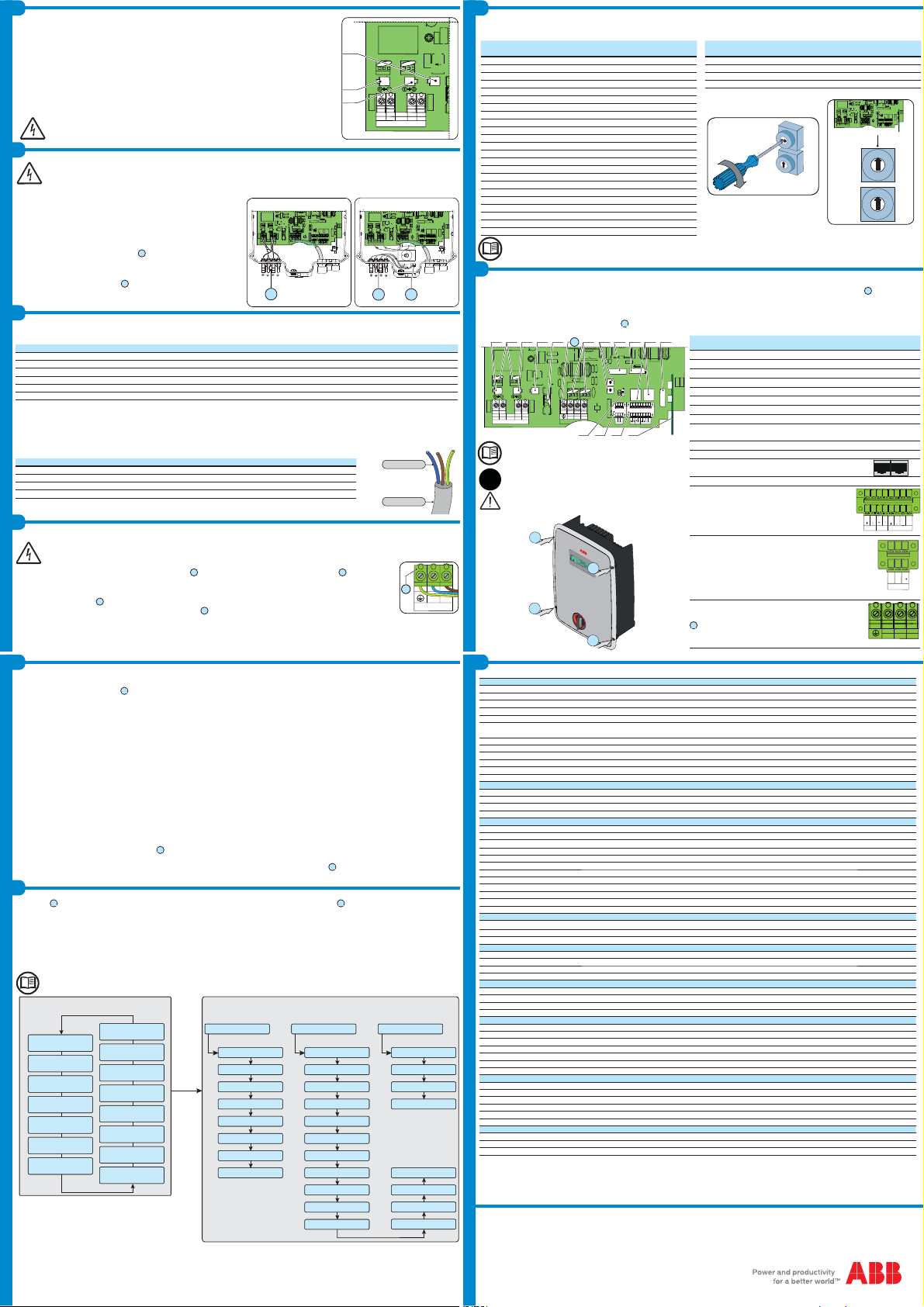
Before connecting the inverter to the distribution grid it is necessary to set the country standard by manipulating the two rotary switches a09.
%HIRUHFRQQHFWLQJWKHLQYHUWHUWRWKHGLVWULEXWLRQJULGLWLVQHFHVVDU\WRVHWWKHFRXQWU\VWDQGDUGE\PDQLSXODWLQJWKHWZRURWDU\VZLWFKHVD
7DEOHFRXQWU\VWDQGDUGDQGODQJXDJH
7KHVHWWLQJVEHFRPH¿[HGDIWHUKRXUVRIRSHUDWLRQRIWKHLQYHUWHUWKH39JHQHUDWRUVLPSO\KDVWREHXQGHUSRZHU
7KHVWDQGDUGIRUWKH,WDOLDQJULGZKLFKPXVWEHVHWGXULQJLQVWDOODWLRQLV&(,#9,17(51$/3URWHFWLRQ
Switch Country Grid Standard
(name displayed) 'LVSOD\
language
12
0 0 NON-ASSIGNED ENGLISH
0 1 GERMANY VDE 0126 @ 230V Single Phase (VDE 0126) GERMAN
0 2 UL1741 @ 208V Single Phase (UL208sing) ENGLISH
0 3 UL1741 @ 240V Split Phase (UL240spl) ENGLISH
0 4 UL1741 @ 277V Single Phase (UL277sing) ENGLISH
0 5 ENELGUIDA @ 230V Single Phase (ENEL) ITALIAN
0 6 SPAIN RD 1699 @ 230V (RD 1699) SPANISH
0 7 UK – G83 @ 230V (UK G83) ENGLISH
0 9 IRELAND @ 230V (IRELAND) ENGLISH
0 A AUSTRALIA @ 230V (AS 4777) ENGLISH
0 B ISRAEL @ 230V (ISRAEL) ENGLISH
0 D FRANCE @ 230V (FRANCE) FRENCH
0 E NETHERLANDS @ 230V (NETHERL) DUTCH
0 F GREECE @ 230V (GREECE) ENGLISH
1 0 PORTUGAL@ 230V (PORTUGAL) ENGLISH
1 1 CORSICA@ 230V (CORSICA) FRENCH
1 2 HUNGARY@ 230V (HUNGARY) ENGLISH
1 3 CHINA@ 230V (CHINA) ENGLISH
1 4 KOREA@ 220V (KOREA) ENGLISH
1 5 TAIWAN @ 230V (TAIWAN) ENGLISH
1 6 CHECARepublic @ 230V (CZECH) CZECH
1 7 GERMANY–VDEAR-N-4105 @230V (VDE 4105) GERMAN
1 8 ENELCEI-021 @ 230V INTERNAL Prot. (CEI021 IN) ITALIAN
Switch Country Grid Standard
(name displayed) 'LVSOD\
language
12
1 9 CEI-021 @ 230V EXTERNALProtection (CEI021 EX) ITALIAN
1 B SOUTH AFRICA @ 230V (S.AFRICA) ENGLISH
1 E BELG C10-11 110% @ 230V (C1011 110) FRENCH
1 F BRAZIL @ 220V (BRAZIL) ENGLISH
RS485CARD
J24
RS485(B)
17
1
18
J15
1
J16
2
J6
1
RS485
T/R
T/R
RTN
LNK
J14
BT1
CR2032
WIND
REM
WT
WT
R
R
RS485(A)
J13
ALARM
N.C.
N.O.
C
TERM.120
ON
O
S3
17
MEMORCARD
J4
18
K4
J23
S1
1
S2
2
N
1
L
2
MO3
3
MO4
J25
RED
I
I
BLACK
W4
W3
WITE
NDMODE
W2
RID
MO2
J10
3
IN
4
J201
J5
1
5
2

6
14
11
J
DCIN
IN
1
IN
2
J1
J7
1
MO1
IN
J17J18
J8
1
a09
1
2
0
1
2
3
4
5
6
7
8
9
A
B
C
D
E
F
0
1
2
3
4
5
6
7
8
9
A
B
C
D
E
F
0
1
2
3
4
5
6
7
8
9
A
B
C
D
E
F
2
1
0
1
2
3
4
5
6
7
8
9
A
B
C
D
E
F
RS485 CARD
J24
RS485(B)
17
1
18
J15
1
J16
2
J6
1
RS485
T/R
T/R
RTN
LNK
J14
BT1
CR2032
WIND
REM
WT
WT
R
R
RS485(A)
J13
ALARM
N.C.
N.O.
C
TERM.120
ON
OFF
S3
17
MEMORY CARD
J4
18
K4
J23
S1
1
S2
2
N
1
L
2
MOV3
3
MOV4
J25
RED
GFI
GFI
BLACK
W4
W3
WHITE
GND_MODE
W2
GRID
MOV2
J10
3
+IN
4
J20 F1
J5
1
5
2
9
6
14
11
J9
DC IN
-IN
1
-IN
2
J19
J7
1
MOV1
+IN
J17 J18
J8
1
a01 a07 a08a09
a10
a11
a12
a13
a14
a15
a06a02a03 a04 a05 09
Connections of the signals to the main board
Each cable which must be connected to the connectors of the communication and control signals must pass through the two service cable glands
06
(shown in the
picture).
The available cable glands are two M20s that can take a cable with a diameter of 7 mm to 13 mm. Two-hole gaskets are supplied for insertion in the cable
gland, which allow two separate cables with cross-section of up to 5 mm to go through.
The signal cables are connected to the main board
05
inside the inverter by means of the terminal connectors supplied.
Please refer to the manual for details of the connections and
functions available on the main board
:KHQ\RXKDYH¿QLVKHGFRQQHFWLQJDQGFRQ¿JXULQJWKHLQYHUWHU
you must close the front cover (tightening torque 2.2Nm), insert
ing the screws in the order shown
IP65
5HI
manual 5HI
inverter 'HVFULSWLRQ
a01 J9 - J10 Input varistors
a02 J5 &RQQHFWRUIRUÀRDWLQJJURXQGRIWKHLQSXWV
a03 J7 Connector for negative grounding of the inputs
a04 J8 Connector for positive grounding of the inputs
a05 F1 - J25 PTC
a06 J11 - J12Output varistors
a07 J4 Inverter data memory card housing
a08 BT1 Battery housing
a09 S1 - S2 Rotary switches for setting the standard of the country and the
language of the display
a10 S3 Switch for setting the termination resistance of the RS485 line
a11 J16 RS485 communication card housing
a12 J13 - J14Connection of the RS485 line on RJ45
connector
1
a13 J6 - J15 Radiomodule card slot
a14 J24
Terminal block for connection of:
- PC RS485 serial connection (to
connect local or remote monitoring
systems)
- Remote ON/OFF
- Tachometer signal (WIND version)
a15 J23
7HUPLQDOEORFNFRQQHFWLQJWRWKHFRQ¿JXUDEOH
relay that allows connection of external devices
which, according to the mode selected in the
menu SETTINGS>Alarm can, for example,
signal malfunctions. The operating modes that
can be set are:
3URGXFWLRQ$ODUP$ODUPFRQ¿JXUD-
ble) -Crepuscolar
09
J21 - J22AC output terminal board
UNO
1
3
4
2
RS485
T/R
T/R
RTN
LNK
WIND
REM
WT
WT
R
R
N
1
L
23
GRID
ALARM
N.C.
NO.
C
The inverter commissioning procedure is as follows:
- Turn theAC+DC disconnect switch
07
to the ON position
- ,IWKHUHDUHWZRVHSDUDWHH[WHUQDOGLVFRQQHFWVZLWFKHVRQHIRU'&DQGWKHRWKHUIRU$&¿UVWFORVHWKH$&GLVFRQQHFWVZLWFKDQGWKHQWKH'&GLVFRQQHFW
switch. There is no order of priority for opening the disconnect switches.
- :KHQWKHLQYHUWHUKDVSRZHUWKH¿UVWFKHFNSHUIRUPHGLVWKHRQHUHODWLQJWRWKHLQSXWYROWDJH
1.,IWKH'&LQSXWYROWDJHLVORZHUWKDQWKH9VWDUWYROWDJHYROWDJHUHTXLUHGWREHJLQWKHLQYHUWHU¶VJULGFRQQHFWLRQWKHELFRQUHPDLQVRIIDQGWKH³:DLWLQJ
sun” message is displayed b10.
2.If the DC input voltage is higher than the Vstart voltage the b14 icon is displayed and the inverter goes to the next stage of the controls.
,QERWKFDVHVWKHYROWDJHOHYHOVDQGLQSXWFXUUHQWDUHGLVSOD\HGLQWKHEDQGE¿HOGV
- The inverter performs a control of grid parameters. The b22 icon, which represents the grid distribution, can have different statuses:
3.not present, if the mains voltage results as absent.
4.ÀDVKLQJLIWKHPDLQVYROWDJHLVSUHVHQWEXWRXWVLGHWKHSDUDPHWHUVGLFWDWHGE\WKHVWDQGDUGRIWKHFRXQWU\RILQVWDOODWLRQ
5.turns on, if the mains voltage is present and within the parameters dictated by the standard of the country of installation. In this condition, the inverter starts
WKHVHTXHQFHRIJULGFRQQHFWLRQ
If the input voltage and the grid voltage are within the inverter operating intervals, connection to the grid will commence. After the inverter is con
nected, the icons on the whole line b21 will come on steady.
Once the connection sequence has been completed, the inverter starts to operate and indicates its correct operation by making a sound and by the
JUHHQ/('FRPLQJRQVWHDG\RQWKH/('SDQHO
14
.
,IWKHLQYHUWHUVLJQDOVDQ\HUURUVZDUQLQJVWKHPHVVDJHVDQGWKHLUFRGHVZLOOEHLQGLFDWHGRQWKHGLVSOD\
12
. This state will also cause switching of
WKHPXOWLIXQFWLRQUHOD\VHWWRDODUPPRGHLQWKHPHQX6(77,1*6!$ODUPZKLFKDFWLYDWHVDQ\H[WHUQDOVLJQDOOLQJGHYLFHWKDWPD\EHFRQQHFWHG
812,287' 812,287'
Input
Absolute Maximum Input Voltage (Vmax,abs) 520 V
Input Activation Voltage (Vstart) 9DGM9
Input operating range (Vdcmin...Vdcmax) 0.7 x Vstart...520 V
Rated DC Input Power (Pdcr) 2100 Wp 2600 Wp
Number of Independent MPPTs 1
Maximum Input Power for each MPPT (PMPPTmax) ³:/LQHDU'HUDWLQJ)URP0$;WR
1XOO>9903379@´
³:/LQHDU'HUDWLQJ)URP0$;WR
1XOO>9903379@´
MPPT Input DC Voltage Range (VMPPTmin,f ... VMPPTmax,f) at Pacr 200...470 V
Maximum DC Input Current (Idcmax) / for each MPPT (IMPPTmax) 12,5 A/ 12,5A 12.8 A/ 12.8A
Maximum Input Short Circuit Current for each MPPT 15.0 A
Maximum Backfeed current (from AC to DC side) Negligible
Number of DC Inputs Pairs for each MPPT 2
DC Connection Type Tool Free PV Connector WM / MC4
Input protection
Reverse Polarity Protection Yes, from limited current source
Input Overvoltage Protection for each MPPT - Varistor 2
Photovoltaic Array Isolation Control According to local standard
DC Switch Rating for each MPPT (-S Version) 16 A/ 600 V
Output
AC Grid Connection Type Single phase
Rated AC Power (Pacr) 2000 W 2500 W
Maximum AC Output Power (Pacmax) 2200 W (4) 2750 W (5)
Rated AC Grid Voltage (Vac,r) 230 V
AC Voltage Range 180...264 V (1)
Maximum AC Output Current (Iac,max) 10.5 A 12.5 A
Maximum output fault current <20Arms (60mS)
5DWHG2XWSXW)UHTXHQF\IU +]
2XWSXW)UHTXHQF\5DQJHIPLQIPD[ +](2)
Nominal Power Factor (Cosphiac,r) > 0.990
Total Harmonic Distortion of Current < 2%
AC Connection Type Screw terminal block
Output protection
Anti-Islanding Protection According to local standard
Maximum AC Overcurrent Protection 15.0 A
Output Overvoltage Protection - Varistor 2 (L - N / L- PE)
Operating performance
0D[LPXP(I¿FLHQF\ȘPD[ 96.3%
:HLJKWHG(I¿FLHQF\(852&(& 95.1% / - 95.4% / -
Power Input Treshold 24.0 W
Stand-by Consumption < 8.0 W (3)
Communication
Wired Local Monitoring PVI-USB-RS232_485 (opt.), PVI-DESKTOP (opt.)
Remote Monitoring PVI-AEC-EVO (opt.), VSN700 Data Logger (opt.)
Wireless Local Monitoring PVI-DESKTOP (opt.) with PVI-RADIOMODULE (opt.)
User Interface Graphic display
Environmental
Ambient Temperature Range -25...+60°C /-13...140°F with derating above 45°C/113°F
Storage Temperature -40...80°C (-40...+176°F)
Relative Humidity 0...100% condensing
(QYLURQPHQWDOSROOXWLRQFODVVL¿FDWLRQIRUH[WHUQDOHQYLURQPHQW 3
Noise Emission < 50 db(A) @ 1 m
Maximum Operating Altitude without Derating 2000 m / 6560 ft
Environmental Category Outdoor
Physical
Environmental Protection Rating IP 65
Cooling Natural
Dimension (H x W x D) 518mm x 367mm x 161mm / 20.4” x 14.4” x 6.3”
Weight < 17 kg / 37.4 lb
Mounting System Wall Bracket
Overvoltage Category in accordance with IEC 62109-1 II (DC input) III (AC output)
Safety
Isolation Level HF transformer
Safety Class I
Marking &(+]RQO\
7KH$&YROWDJHUDQJHPD\YDU\GHSHQGLQJRQVSHFL¿FFRXQWU\JULGVWDQGDUG   /LPLWHGWR:IRU*HUPDQ\
7KH)UHTXHQF\UDQJHPD\YDU\GHSHQGLQJRQVSHFL¿FFRXQWU\JULGVWDQGDUG   6LQFHWKHLUDSSOLFDELOLW\GDWHVOLPLWHGWRSODQWSRZHUN:
1LJKWWLPHFRQVXPSWLRQ:   /LPLWHGWRSODQWSRZHUN9$
4. Limited to 2000 W for Germany
5HPDUN)HDWXUHVQRWVSHFL¿FDOO\OLVWHGLQWKHSUHVHQWGDWDVKHHWDUHQRWLQFOXGHGLQWKHSURGXFW
RS485CARD
J24
RS485(B)
17
1
18
J15
1
J16
2
J6
1
RS485
T/R
T/R
RTN
LNK
J14
BT1
CR2032
WIND
REM
WT
WT
R
R
RS485(A)
J13
ALARM
N.C.
N.O.
C
TERM.120
ON
OFF
S3
17
MEMORY CARD
J4
18
K4
J23
S1
1
S2
2
N
1
L
2
MOV3
3
MOV4
J25
RED
GFI
GFI
BLACK
W4
W3
WHITE
GND_MODE
W2
GRID
MOV2
J10
3
+IN
4
J20F1
J5
1
5
2
9
6
14
11
J9
DC IN
-IN
1
-IN
2
J19
J7
1
MOV1
+IN
J17J18
J8
1
10
Standard Version
RS485CARD
J24
RS485(B)
17
1
18
J15
1
J16
2
J6
1
RS485
T/R
T/R
RTN
LNK
J14
BT1
CR2032
WIND
REM
WT
WT
R
R
RS485(A)
J13
ALARM
N.C.
N.O.
C
TERM.120
ON
OFF
S3
17
MEMORYCARD
J4
18
K4
J23
S1
1
S2
2
N
1
L
2
MOV3
3
MOV4
J25
RED
GFI
GFI
BLACK
W4
W3
WHITE
GND_MODE
W2
GRID
MOV2
J10
3
+IN
4
J20F1
J5
1
5
2
9
6
14
11
J9
DC IN
-IN
1
-IN
2
J19
J7
1
MOV1
+IN
J17 J18
J8
1
0710
69HUVLRQ
NL
GRID
09

Other manuals for UNO-2.0-I-OUTD

1

This manual suits for next models

3

Other ABB Inverter manuals

ABB PVS800-IS User manual

ABB

ABB PVS800-IS User manual

ABB PVI-3.0-TL-OUT User manual

ABB

ABB PVI-3.0-TL-OUT User manual

ABB UNO-DM-6.0-TL-PLUS User manual

ABB

ABB UNO-DM-6.0-TL-PLUS User manual

ABB UNO-DM-6.0-TL-PLUS-US-Q User manual

ABB

ABB UNO-DM-6.0-TL-PLUS-US-Q User manual

ABB UNO-DM-3.3-TL-PLUS-US-Q User manual

ABB

ABB UNO-DM-3.3-TL-PLUS-US-Q User manual

ABB EMIU 1500W User manual

ABB

ABB EMIU 1500W User manual

ABB EMIU 400W User manual

ABB

ABB EMIU 400W User manual

ABB MICRO-0.25-I-OUTD-US-208/240 User manual

ABB

ABB MICRO-0.25-I-OUTD-US-208/240 User manual

ABB UNO-DM-1.2-TL-PLUS User manual

ABB

ABB UNO-DM-1.2-TL-PLUS User manual

ABB REACT 2 Series User manual

ABB

ABB REACT 2 Series User manual

ABB TRIO-5.8-TL-OUTD-S User manual

ABB

ABB TRIO-5.8-TL-OUTD-S User manual

ABB PVS-166-TL-US User manual

ABB

ABB PVS-166-TL-US User manual

ABB PVS-175-TL Series User manual

ABB

ABB PVS-175-TL Series User manual

ABB PVS-50-TL User manual

ABB

ABB PVS-50-TL User manual

ABB REACT-3.6-TL Installation and operating instructions

ABB

ABB REACT-3.6-TL Installation and operating instructions

ABB UNO-2.0-I-OUTD User manual

ABB

ABB UNO-2.0-I-OUTD User manual

ABB PVS-60-TL-US User manual

ABB

ABB PVS-60-TL-US User manual

ABB UNO-DM-1.2-TL-PLUS User manual

ABB

ABB UNO-DM-1.2-TL-PLUS User manual

ABB TRIO-20.0-TL-OUTD-US User manual

ABB

ABB TRIO-20.0-TL-OUTD-US User manual

ABB UNO-2.5-I-OUTD User manual

ABB

ABB UNO-2.5-I-OUTD User manual

ABB PVS980-58 Use and care manual

ABB

ABB PVS980-58 Use and care manual

ABB UNO-DM-1.2-TL-PLUS User manual

ABB

ABB UNO-DM-1.2-TL-PLUS User manual

ABB PVS-175-TL-SX2 User manual

ABB

ABB PVS-175-TL-SX2 User manual

ABB TRIO-50.0 User manual

ABB

ABB TRIO-50.0 User manual

Popular Inverter manuals by other brands

Lenze i950 Series Project Planning

Lenze

Lenze i950 Series Project Planning

Nibe PVK 10-10 Installer manual

Nibe

Nibe PVK 10-10 Installer manual

ELCART 13/16600 instruction manual

ELCART

ELCART 13/16600 instruction manual

Hitachi NES1-004SB Quick reference guide

Hitachi

Hitachi NES1-004SB Quick reference guide

Immergas NATURAL SOL 150 V2 Instructions and Recommendations

Immergas

Immergas NATURAL SOL 150 V2 Instructions and Recommendations

IFR 2026Q operating manual

IFR

IFR 2026Q operating manual

DSPM Fortress 3 Maintenance manual

DSPM

DSPM Fortress 3 Maintenance manual

BYGD SW400 user manual

BYGD

BYGD SW400 user manual

SolarMax SHT Series instruction manual

SolarMax

SolarMax SHT Series instruction manual

REMKO MVT Series Operation,technology,spare parts

REMKO

REMKO MVT Series Operation,technology,spare parts

Carbest LithPowerUnit 80 User instruction

Carbest

Carbest LithPowerUnit 80 User instruction

Voltronic Power AXPERT MAX II 8KW Service manual

Voltronic Power

Voltronic Power AXPERT MAX II 8KW Service manual

Rheem GEN-12S Warranty

Rheem

Rheem GEN-12S Warranty

V-TAC 11834 instruction manual

V-TAC

V-TAC 11834 instruction manual

STMicroelectronics STEVAL-CTM004V1 user manual

STMicroelectronics

STMicroelectronics STEVAL-CTM004V1 user manual

SMA SUNNY BOY 1.5 Quick reference guide

SMA

SMA SUNNY BOY 1.5 Quick reference guide

LAMBERTI ELEKTRONIK LATHERM SOL BASIS operating manual

LAMBERTI ELEKTRONIK

LAMBERTI ELEKTRONIK LATHERM SOL BASIS operating manual

SEW-Eurodrive MOVIDRIVE compact Series System manual

SEW-Eurodrive

SEW-Eurodrive MOVIDRIVE compact Series System manual

manuals.online logo
manuals.online logoBrands
  • About & Mission
  • Contact us
  • Privacy Policy
  • Terms and Conditions

Copyright 2025 Manuals.Online. All Rights Reserved.