manuals.online logo
Brands
  1. Home
  2. •
  3. Brands
  4. •
  5. Vitek
  6. •
  7. Security Camera
  8. •
  9. Vitek VTC-TNB8RMS User manual

Vitek VTC-TNB8RMS User manual

Other Vitek Security Camera manuals

Vitek VTD-VH49VP4 User manual

Vitek

Vitek VTD-VH49VP4 User manual

Vitek VTC-IRH70 User manual

Vitek

Vitek VTC-IRH70 User manual

Vitek VTC-IRLED24H User manual

Vitek

Vitek VTC-IRLED24H User manual

Vitek VTC-IRE70 User manual

Vitek

Vitek VTC-IRE70 User manual

Vitek Transcendent Series User manual

Vitek

Vitek Transcendent Series User manual

Vitek TRANSCENDENT VTD-HOCR2812-VB User manual

Vitek

Vitek TRANSCENDENT VTD-HOCR2812-VB User manual

Vitek VTC-IRA70/650 User manual

Vitek

Vitek VTC-IRA70/650 User manual

Vitek VTD-AR2812 User manual

Vitek

Vitek VTD-AR2812 User manual

Vitek VTC-C63 User manual

Vitek

Vitek VTC-C63 User manual

Vitek VTD-MD5CH User manual

Vitek

Vitek VTD-MD5CH User manual

Vitek Transcendent VTC-TNT8RFEA-2 User manual

Vitek

Vitek Transcendent VTC-TNT8RFEA-2 User manual

Vitek VTC-THB8R2 User manual

Vitek

Vitek VTC-THB8R2 User manual

Vitek VTC-C544 User manual

Vitek

Vitek VTC-C544 User manual

Vitek VT-PTZ220HD User manual

Vitek

Vitek VT-PTZ220HD User manual

Vitek VTD-AR2812/I User manual

Vitek

Vitek VTD-AR2812/I User manual

Vitek Mighty VTD-MP1850DN User manual

Vitek

Vitek Mighty VTD-MP1850DN User manual

Vitek VTC-IRX36/3895 User manual

Vitek

Vitek VTC-IRX36/3895 User manual

Vitek VTC-T4T3HR2MD User manual

Vitek

Vitek VTC-T4T3HR2MD User manual

Vitek VIRTUOSO User manual

Vitek

Vitek VIRTUOSO User manual

Vitek Transcendent VTD-TND24R5F2 User manual

Vitek

Vitek Transcendent VTD-TND24R5F2 User manual

Vitek Alpha VTC-IRLED24 User manual

Vitek

Vitek Alpha VTC-IRLED24 User manual

Vitek VT-PTZ36W Manual

Vitek

Vitek VT-PTZ36W Manual

Vitek Mighty VTD-MP2810WDR User manual

Vitek

Vitek Mighty VTD-MP2810WDR User manual

Vitek VTD-C75 User manual

Vitek

Vitek VTD-C75 User manual

Popular Security Camera manuals by other brands

Okina USA SIR36-870VF650LP user manual

Okina USA

Okina USA SIR36-870VF650LP user manual

Divio NDR155PA user manual

Divio

Divio NDR155PA user manual

Easy Access EasyGuard user manual

Easy Access

Easy Access EasyGuard user manual

Vivotek FD9389-EHV-v2 Quick installation guide

Vivotek

Vivotek FD9389-EHV-v2 Quick installation guide

TUYA COSMO W2 manual

TUYA

TUYA COSMO W2 manual

Eusso UNC7500-IR Advanced installation guide

Eusso

Eusso UNC7500-IR Advanced installation guide

urmet domus 1096/204 user manual

urmet domus

urmet domus 1096/204 user manual

VC VC20 series operating manual

VC

VC VC20 series operating manual

Axis Q1614 installation guide

Axis

Axis Q1614 installation guide

ieGeek DD201 manual

ieGeek

ieGeek DD201 manual

VADDIO ClearVIEW HD-USB PTZ 999-6990-000 Installation and user guide

VADDIO

VADDIO ClearVIEW HD-USB PTZ 999-6990-000 Installation and user guide

Vicon V662-D-1 Installation and operation guide

Vicon

Vicon V662-D-1 Installation and operation guide

Grundig GCH-K0274P owner's manual

Grundig

Grundig GCH-K0274P owner's manual

Lorex VANTAGE LBC7032 quick start guide

Lorex

Lorex VANTAGE LBC7032 quick start guide

4xem WPT Specifications

4xem

4xem WPT Specifications

Samsung SCV-3082 Specifications

Samsung

Samsung SCV-3082 Specifications

Lumens VC-A50PNW installation guide

Lumens

Lumens VC-A50PNW installation guide

Security Cameras Direct CFC6042IR user manual

Security Cameras Direct

Security Cameras Direct CFC6042IR user manual

manuals.online logo
manuals.online logoBrands
  • About & Mission
  • Contact us
  • Privacy Policy
  • Terms and Conditions

Copyright 2025 Manuals.Online. All Rights Reserved.

VITEK
VTC-TNB8RMS
Transcendent Series
8 Megapixel H.265 Indoor/
Outdoor WDR IP Bullet Camera
with 48 IR LED Illumination
QUICK START GUIDE
FOR FULL PRODUCT MANUAL
FOLLOW THE QR CODE BELOW
FEATURES
• 1/2.5” 8.0 Megapixel Progressive Scan CMOS image sensor
• Up to 30fps live view @ 8 MegaPixel (3840x2160)
• 3.3 ~ 12 mm Motorized Varifocal Lens
• 48 IR LED Illumination with a 165’ IR Range
• 120dB Super Wide Dynamic Range (WDR)
• True Mechanical Day/Night function by ICR
• XD-DNR (2D-DNR & 3D-DNR) Noise Reduction
• Fully Programmable Intelligent Analytics including Face Detection,
Object Removal/Museum Search, Exception, Line Crossing, Area
Intrusion, People Counting, People Intrusion, Crowd Density Monitoring
• H.265/H.264/MJPEG Triple Streaming
• Secondary Video Output (CVBS)
• Remote Viewing via CMS, Internet Explorer, and iOS & Android Apps
• ONVIF Compliant
•IP66
Weather
Resistance
•
Optional
Junction
Box
Mounts
(VT-TJB03 and VT-TJB01) Available
• 12VDC &PoE (Power over Ethernet) Operation
1
23
Installation
Before beginning installation, make sure that the wall or ceiling is
strong enough to withstand 3 times the weight of the camera. The
mounting steps are as follows:
1. Attach the drill template to
the place where you want to
install the camera, then drill
3 screw holes and 1 cable
hole (if you want to route the
cables through the mounting
base) according to the drill
template
2. Route the cables and connect the power & video cables, use the
rubber plug to fill the gap of the mounting base. then secure the
mounting base to the ceiling or wall with screws.
Ceiling Mounted Wall Mounted
and a Motorized Varifocal Lens
Components and Accessories
Overview
Camera
Quick Guide
Screws
Hex Wrench
Drill Template
Rubber Plug
Waterproof Cap
Service Port Cable
2
3
4
5
6
1
7
8
9
Cable Connections
Alarm
Weather Resistant Network Coupler
First connect the Waterproof Cap to an Ethernet patch cable, then
connect the cameras ethernet adaptor. If not powering the camera with
PoE, also connect the power Cable to an approved 12VDC Power
Supply.
1. Loosen the nut from the Weather Resistant Network Coupler,
2. Run ethernet cable through coupler, then attach a RJ-45 connector.
3. Tighten the nut and coupler for a weather resistant seal.
Network Cable
Optional 12VDC
Not needed with PoE
ALM: COM
ALM: NO
ALM: IN
ALM: GND
RS-485 +
RS-485 -
A lar m I nput: Join the grounding ends of the sensor and the camera and then connect th
signal cable of the sensor to the alarm input port of the camera.
A lar m Output: Loosen the screws in the alarm output port. Then insert the signal wires
of the alarm output devices into the port of COM and OPEN separately. Finally tighten
the screws. Some of the external alarm output devices need the power supply.
10
1
2
3
4
5
6
7
8
9
10
RJ-45 Ethernet
Audio In
Audio Out
CVBS Output
Alarm I/O
RS-485
Power Cable
Reset
Service Port
MicroSD Card Slot
SD
• Micro SD Card support up to 128GB
5
4
36
5
LAN Configuration
The camera can be accessed on the local network either using the
IP-Tool or directly in a web browser.
Accessing the Camera Using the IP-Tool
1. Make sure the camera and PC are connected to the LAN.
For example, the IP address of your computer
is 192.168.13.4. So the IP address of the
camera shall be changed to 192.168.13.X.
After modification, please input the password
of the administrator and click “Modify” button
to modify the setting.
** Default admin password: “123456".
4. Double-click the IP address and then the system will pop up the web
browser to connect IP-CAM . IE browser will download the Active X
control automatically. After downloading, a login window will pop up
as shown below:
Input the user name and password to log in.
Default user name: admin / Default password: 123456.
Directly Access Through a Web Browser
The default network settings are as shown below:
IP address: 192.168.226.201 HTTP: 80
Subnet Mask: 255.255.255.0 Data Port: 9008
Gateway: 192.168.226.1
You may use the above default settings when you log in the camera for
the first time.
1. Manually set the IP address of the PC and the network segment
should be as the same as the default settings of IP-CAM. Open the
network and share center. Click “Local Area Connection” to pop up
the following window.
Select “Properties” and then select Internet protocol according to the
actual situation (for example: IPV4). Next, click “Properties” button to
set the network of the PC.
2. Open the IE Browser and input the default address of IP-CAM and
confirm. The IE browser will download Active X control automatical-
ly.
3. After downloading Active X control, the login dialog box will pop up.
4. Input the default username and password and then enter to view.
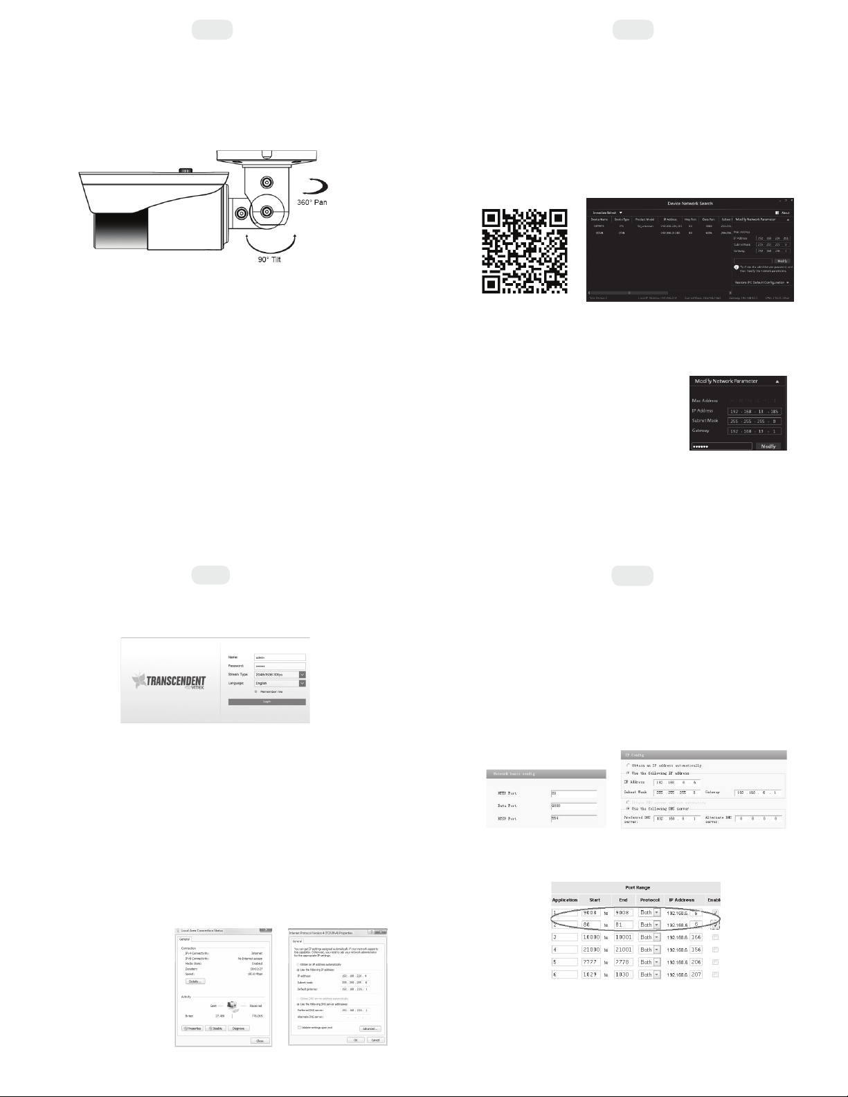
WAN Configuration
Access the camera by the router or virtual server for example.
1. Make sure the camera is connected to the LAN; Then log into the
camera via LAN and go to System Congfig→Network Config→Port
menu to set up the port number.
2. Enter System Config→Network Config→IP Address menu to modify
the IP address.
4. Open the web browser and input its WAN IP and HTTP port to
access the IP-CAM.
3. Go to the router’s management interface through IE browser to
forward the IP address and port of IP-CAM in the “Virtual Server”.
7
Installation
3. Loosen the mount lock to adjust the Pan and Tilt of the camera, then
tighten the mount lock to secure the viewing angle adjustments.
4.
Carefully remove the protective film from the lens to complete the installation.
2. Locate the IP-Tool installer on the Vitek Website:
vitekcctv.com/Downloads/Software/Transcendent-IPTool_v2.0.2.zip
(also available via the QR code below)
Then install on the PC. Open the installed application.
3. Modify the IP address. The default IP address is 192.168.226.201.
Click the information of the camera listed in the above table to show
the network information on the right side. Modify the IP address and
gateway of the camera and make sure its network address is in the
same local network segment as the computer’s. Please modify the
IP address of your device according to the practical situation.