Vitesse VSC8211 User manual

VPPD-03472
Revision 1.0
December 2013 Vitesse Proprietary
VSC8211 Eva uation Board
User Guide

Revision 1.0
December 2013 Vitesse Proprietary Page 2 of 13
Vitesse
www.vitesse.com
Vitesse Semiconductor Corporation (“Vitesse”) retains the right to make changes to its
products or specifications to improve performance, re iabi ity or manufacturabi ity. A
information in this document, inc uding descriptions of features, functions,
performance, technica specifications and avai abi ity, is subject to change without
notice at any time. Whi e the information furnished herein is he d to be accurate and
re iab e, no responsibi ity wi be assumed by Vitesse for its use. Furthermore, the
information contained herein does not convey to the purchaser of microe ectronic
devices any icense under the patent right of any manufacturer.
Vitesse products are not intended for use in ife support products where fai ure of a
Vitesse product cou d reasonab y be expected to resu t in death or persona injury.
Anyone using a Vitesse product in such an app ication without express written consent
of an officer of Vitesse does so at their own risk, and agrees to fu y indemnify Vitesse
for any damages that may resu t from such use or sa e.
Safety of Laser Products, IEC 60825. Whi e Vitesse products support IEC 60825, use of
Vitesse products does not ensure comp iance to IEC 60825. Buyers are responsib e for
ensuring comp iance to IEC 60825. Buyers must fu y indemnify Vitesse for any
damages resu ting from non-comp iance to IEC 60825.
Vitesse Semiconductor Corporation is a registered trademark. A other products or
service names used in this pub ication are for identification purposes on y, and may be
trademarks or registered trademarks of their respective companies. A other
trademarks or registered trademarks mentioned herein are the property of their
respective ho ders.
Copyright © 2013 Vitesse Semiconductor Corporation

VSC8211 Eva uation Board
User Guide
Revision 1.0
December 2013 Vitesse Proprietary Page 3 of 13
Contents
Revision History ................................................................................ 4
1 Introduction .............................................................................. 5
2 General Description ................................................................... 6
2.1
Hardware Features ............................................................................................. 6
2.1.1
Power Connections .................................................................................. 6
2.1.2
Copper Port RJ45 Connections .................................................................. 6
2.1.3
SGMII MAC Interface via SMA .................................................................... 6
2.1.4
GMII, RGMII, MII, TBI and RTBI MAC Interface .......................................... 7
2.1.5
Fiber Transceiver Interface (SFP Cage) ...................................................... 7
2.1.6
Switches ................................................................................................ 7
2.1.7
Taitien 25MHz Crysta ............................................................................. 7
2.1.8
Externa RefC k
Option
............................................................................. 7
2.1.9
Si abs Microcontro er .............................................................................. 7
2.1.10
EEPROM Option ...................................................................................... 8
2.1.11
CMODE Pins (Pin-Strap mode) .................................................................. 8
2.1.12
LED Interface ......................................................................................... 8
2.1.13
CLOCKOUT SMA ..................................................................................... 8
2.2
Software Requirements ...................................................................................... 8
3 Quick tart ................................................................................ 9
3.1
Board Configuration ........................................................................................... 9
3.1.1
Power Up ............................................................................................... 9
3.1.2
C ock and Reset ..................................................................................... 10
3.2
GUI and Driver Insta ation ................................................................................ 10
3.3
Using the GUI ................................................................................................... 11
3.4
Test Cases ....................................................................................................... 12
3.4.1
CAT5 to SGMII with C ause 37 AutoNeg Enab ed ........................................ 12
3.4.2
CAT5 to RGMII ...................................................................................... 12
3.5
Usefu Registers ................................................................................................ 13
3.5.1
Ethernet Packet Generator ...................................................................... 13
3.5.2
Far-End Loopback .................................................................................. 13
3.5.3
Near-End Loopback ................................................................................ 13
4 Additional Information ............................................................ 13
Figures
Figure 1.
VSC8211EV ................................................................................................ 5
Figure 2.
MDIO/MDC Jumpers on J23 to SiLabs F340 pins .............................................. 8
Figure 3.
USBXpress as Seen From the Device Manager Window ................................... 10
Figure 4.
Connection Window .................................................................................... 11
Figure 5.
Register List Window .................................................................................. 11

VSC8211 Eva uation Board
User Guide
Revision 1.0
December 2013 Vitesse Proprietary Page 4 of 13
Tables
Tab e 1.
Switch and Jumper Configuration .................................................................. 9
Revision History
Revision Date Description
Rev 1.0 December 18, 2013 First re ease

VSC8211 Eva uation Board
User Guide
Revision 1.0
December 2013 Vitesse Proprietary Page 5 of 13
1Introduction
The VSC8211 device is a ow-power, Gigabit Ethernet transceiver suited for Media
Converters and Ethernet Switches with virtua y any seria or para e MAC interface.
The VSC8211 device a so inc udes Vitesse’s VeriPHY Cab e Diagnostics feature.
This document describes the operation of the VSC8211 Eva uation Board
(VSC8211EV). The Quick Start section describes how to insta and run the graphica
user interface (GUI) to fu y contro the eva uation board.
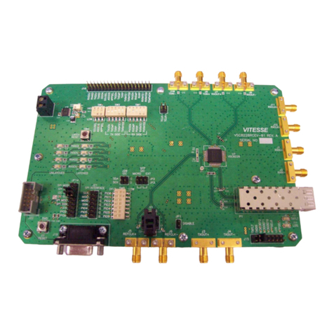
Figure 1. V C8211EV
The fo owing reference documents provide additiona information about the operation
of the VSC8211 eva uation board.

VSC8211 Eva uation Board
User Guide
Revision 1.0
December 2013 Vitesse Proprietary Page 6 of 13
•VSC8211 Datasheet
( https://www.vitesse.com/products/down oad.php?fid=118&number=VSC8211 )
•VSC8211 Eva uation Board GUI
( https://www.vitesse.com/products/down oad.php?fid=5157&number=VSC8211 )
•VSC8211 Eva uation Board Schematics
( https://www.vitesse.com/products/product.php?number=VSC8211 )
2General Description
The VSC8211EV provides the user a way to eva uate the VSC8211 device in mu tip e
configurations. One RJ-45 connector is provided for the copper media interface. The
MAC interface is accessib e via SMA connectors. An SFP cage is avai ab e for seria to
seria configurations, and headers are avai ab e for the para e interface
The VSC8211’s interna registers are accessed via the MDIO bus from an externa
microcontro er driven by an externa PC via USB. The accompanying GUI enab es the
user to read and write the device registers. A ternative y, the VSC8211EV a so has the
capabi ity to configure the VSC8211 through an EEPROM or Rabbit microcontro er
(not-provided).
The eva uation board has the option to use VSC8211’s interna on-chip osci ator by
connecting a 25MHz crysta to XTAL1 and XTAL2 or an externa reference c ock signa
through the REFCLK SMA (J12).
2.1 Hardware Features
2.1.1 Power Connections
For convenience, the eva uation board runs off a sing e +5VDC power supp y. On board
DC-DC convertors create the +3.3VDC rai for the board and optiona +1.2VDC rai . Power is
supp ied to the upper right corner of the board. Power can be app ied either to the
5.5 x 2.1 mm barre connector (J24) or the banana receptac es (J25 and J26). J27 is an
optiona monitor point for the 1.2V rai . When powered by a bench top supp y the
board may draw up to 3A maximum, modu e inc uded.
2.1.2 Copper Port RJ45 Connections
The RJ45 copper media PHY port (J1) uses a generic RJ45 jack with a discrete Pu se
H5008 magnetic transformer.
2.1.3 GMII MAC Interface via MA
The seria MAC interface is avai ab e through SMA connectors (J2, J4, J3, and J6), inc uding
the optiona SCLK (on J5 and J7).

VSC8211 Eva uation Board
User Guide
Revision 1.0
December 2013 Vitesse Proprietary Page 7 of 13
2.1.4 GMII, RGMII, MII, TBI and RTBI MAC Interface
The para e MAC interfaces are avai ab e through pin headers on J16 and J28.
2.1.5 Fiber Transceiver Interface ( FP Cage)
The Fiber transceiver differentia pair used in the SGMII to SerDes PHY operating mode
is supported with the standard SFP cage (U5).
2.1.6 witches
Switch SW1 a ows the user to se ect the mode of the EECLK/PLLMODE pin. In the on
position a ogic high vo tage (pu -up resistor) configures the device for a 125MHz
reference c ock whi e a ogic ow vo tage (pu -down resistor) se ects a 25MHz
reference c ock option. This is a momentary ON switch which requires the user to ho d
it in the on position for 3 seconds during board power up or device reset.
2.1.7 Taitien 25MHz Crystal
The eva uation board is shipped configured to use the VSC8211’s interna on-chip
osci ator. The jumper on J13 shou d be insta ed in the XTAL ( eft) position, and the
jumper on J8 shou d be insta ed in the PLL enab e or VCC (right) position.
Note Review the required action for SW1 mentioned above.
2.1.8 External RefClk
Option
The user may choose to provide an externa PHY REFCLK via the SMA connector
(J12). The user must configure the device by insta ing a jumper on J8 in the PLL
disab e or ground ( eft) position and insta ing a jumper on J13 in the SMA (right)
position.
2.1.9 ilabs Microcontroller
A Si abs F340 microcontro er is inc uded to faci itate a software interface to the
registers on the VSC8211 through a USB port.
To communicate to the EEPROM or to use a Rabbit microcontro er rather than the
Si abs F340, insta jumpers on J23 and J14 according y.
Note A si k-screen error exists on the PCB for J23 such that the MDIO and MDC
signa s are swapped with the SDA and SCL signa s respective y for the F340 and
Rabbit signa s. Refer to Figure 2 for c arity of the defau t configuration.

VSC8211 Eva uation Board
User Guide
Revision 1.0
December 2013 Vitesse Proprietary Page 8 of 13
Figure 2. MDIO/MDC Jumpers on J23 to iLabs F340 pins
2.1.10 EEPROM Option
The user may choose to configure theVSC8211 via an EEPROM oad. In order to
program the EEPROM proper y, pu -up or pu -down resistors must be configured for
either R6 – R8 or R24 – R26. P ease refer to Section 19 of the datasheet regarding to
EEPROM programming requirement.
2.1.11 CMODE Pins (Pin- trap mode)
On the upper right of the board, there is an option to change the CMODE pin pu -up or
pu -down resistors, R9 - R17 and R27-R34. P ease refer to Section 18 of the datasheet
for the detai on how to program the desired operating condition parameters through
the CMODE configuration bits and how to choose the va ue of each CMODE pu -up or
pu -down resistor.
2.1.12 LED Interface
LED1 to LED5 are avai ab e on the ower eft of the board. P ease refer to Section 14 of
the datasheet for detai s regarding how to configure the LEDs.
2.1.13 CLOCKOUT MA
The user shou d observe a 125MHz output c ock through this SMA if the interna PHY
PLL is operating proper y.
2.2 oftware Requirements
The VSC8211 GUI can be oaded on to any PC or aptop that comp ies with the
fo owing requirements:
1. The PC must run a recent version of MS-Windows. According to the Microsoft
website, the fo owing operating systems can run .NET based app ications:

VSC8211 Eva uation Board
User Guide
Revision 1.0
December 2013 Vitesse Proprietary Page 9 of 13
•Windows 2000
•Windows XP
•Windows Vista
•Windows-7
Note The GUI may be s ower when run on Windows 2000 operating system.
2. Hardware requirements must be considered when dep oying/insta ing .NET
app ications. The minimum hardware requirement for a system running a .NET
app ication is a Pentium 90MHz with 32 MB of RAM. For best performance, a
newer system is recommended a ong with a minimum of 1 GB of RAM.
3. If the .NET Framework 2.0 is not a ready insta ed, it may be obtained from the
fo owing ink:
http://www.microsoft.com/down oads/detai s.aspx?Fami yID=0856EACB-4362-
4B0D-8EDD-AAB15C5E04F5&disp ay ang=en
3Quick tart
3.1 Board Configuration
Prior to powering the board, ensure that the jumpers and switches are in the fo owing
positions.
Table 1. witch and Jumper Configuration
witch/Jumper Position
J23 (MDC) Jumper insta ed connecting DUT MDC to F340 SCL
NOTE: This is due to a ayout error on the PCB
. Refer
to Section 2.1.9 for additiona detai s.
J23 (MDIO) Jumper insta ed connecting DUT MDIO to F340 SDA
NOTE: This is due to a ayout error on the PCB
. Refer
to Section 2.1.9 for additiona detai s.
J15 (TRSTB) Jumper insta ed connecting to GND. This is not
required when R35 is insta ed.
J13 (XTAL1/REFCLK) Jumper insta ed connecting center pin to XTAL.
J8 (PLL ENABLE/DISABLE) Jumper insta ed connecting center pin to PLL ENABLE.
SW1 Ho d in the eft position during power-up and reset.
3.1.1 Power Up
Provide +5VDC to the board by p ugging in the power cab e (inc uded in the kit) to
J24. Two green LEDs shou d i uminate: D12 on the eft side of the board indicating
+3.3VDC present, and D14 indicating +1.2VDC present.

VSC8211 Eva uation Board
User Guide
Revision 1.0
December 2013 Vitesse Proprietary Page 10 of 13
3.1.2 Clock and Reset
Power must be app ied and the c ock (either 25MHz or 125MHz) must be active at the
correct frequency for the prescribed period of time in the datasheet before the RESETB
pin is re eased. PLLMODE and OSCDISB pins are samp ed during the device power-up
or on assertion of RESETB pin.
The board wi be shipped configured for use of the 25MHz crysta thus OSCDISB must
be pu ed up and PLLMODE must be pu ed down during power-up or assertion of
RESETB by setting J8 to the PLL enab e position and ho ding SW-1 in the 25MHz
position upon power-up.
3.2 GUI and Driver Installation
Down oad the VSC8211EV GUI from Vitesse’s website onto a PC that has a USB port.
Insta the GUI by aunching the setup.exe fi e. Once insta ed, connect the USB cab e
between the USB port of the PC and the USB connector (J20) on the eva uation board.
Ensure the MDIO and MDC jumpers are proper y p aced from DUT to F340 on J23 to
estab ish the connection between the VSC8211’s SMI pins and the SiLab F340.
USB communication is assisted by the Si abs USBXpress® drive. If not present on the
PC, the user wi need to down oad the USBXpress Deve opment Kit from the Si icon
Labs website (URL: http://www.si abs.com/products/mcu/Pages/USBXpress.aspx).
Fo ow the insta ation directions after down oading the deve opment kit.
To ensure the USBXpress driver is insta ed and proper y recognizing the eva uation
board, go to Contro Pane and c ick on System>Hardware>Device Manager, and
inspect the Universa Seria Bus contro ers isted to see if “USBXpress Device”
appears. Figure 3 shows that the PC recognizes that a USBXpress Device is connected.
Figure 3. U BXpress as een From the Device Manager Window

VSC8211 Eva uation Board
User Guide
Revision 1.0
December 2013 Vitesse Proprietary Page 11 of 13
3.3 Using the GUI
Launch the GUI either by c icking on the Desktop shortcut or c icking on the “Start –
Programs – Vitesse Semiconductor Corp - VSC8211_Eva uation_System” icons. The
initia window wi detect the attached USB devices automatica y. Figure 4 shows a
typica EVB Connection window.
Figure 4. Connection Window
The EVB seria number shou d appear. If not, c ick on “Scan For USB Devices.” Se ect
that EVB seria number then c ick “Launch GUI”. The Register List window wi appear
as shown in Figure 5.
Figure 5. Register List Window

VSC8211 Eva uation Board
User Guide
Revision 1.0
December 2013 Vitesse Proprietary Page 12 of 13
Verify that the device is up and running by reading MII Register 0. It shou d read back
0x1040. Reading back “0000” or “FFFF” (a 0’s or a 1’s) indicates a prob em.
To read or write the extended MII registers c ick on the ExtMII tab.
An initia ization script may be used to configure mu tip e VSC8211 registers. The
initia ization script is simp y a text fi e which contains a ist of registers to be written.
Se ect the Device item on the top pu down menu area and c ick on Load-A -Registers
option. A pop-up window wi appear. Navigate to and se ect the desired script to be
oaded.
As per Section 31.1 of the datasheet, there are a number of interna registers that
must be changed from their defau t va ue during device initia ization. Use this method
to initia ize the device by oading “vsc8211_workaround33_1.txt” inc uded in the GUI
package under the Script/ directory. GUI Setup
3.4 Test Cases
3.4.1 CAT5 to GMII with Clause 37 AutoNeg Enabled
After power-up or reset, VSC8211 as configured on the eva uation board wi operate
according to CAT5 to SGMII with C ause 37 Auto Negotiation enab ed. The 1G Ethernet
received at the RJ-45 port is routed through the VSC8211 and ooped back via SGMII
through SMA cab es.
1. Set up the copper Ethernet traffic source (e.g., IXIA or Smartbits)
2. Connect an Ethernet cab e to an RJ-45.
3. Loopback SGMII RXDOUT to TXDIN via SMA cab es.
4. Monitor the ink-up bit in MII Register 1, bit 2 (MII 1.2), read twice to update.
Traffic shou d now be f owing.
3.4.2 CAT5 to RGMII
1. Set up the copper Ethernet traffic source (e.g., IXIA or Smartbit) and connect a
CAT5e cab e to the RJ-45.
2. Loopback the RGMII signa s using 0-ohm header jumpers on J16.
3. Write 0x1824 to MII Register 23 (Port 0, PHY Contro #1). This a so sets the
interna RGMII TXC skew to 2.0ns for this board.
4. Write 0x9040 to MII Register 0 (Port 0, SW Reset for PHY Contro setting to take
effect).
5. Monitor the ink-up bit in MII Register 1, bit 2 (MII 1.2), read twice to update.
Traffic shou d be f owing.

VSC8211 Eva uation Board
User Guide
Revision 1.0
December 2013 Vitesse Proprietary Page 13 of 13
3.5 Useful Registers
3.5.1 Ethernet Packet Generator
ExtMII 29E is the Ethernet Packet Generator register. Refer to datasheet for
configuration options.
A bad-CRC counter is in ExtMII 23.7:0. This counter wi be saturate at 0xFF and is
c eared when read.
3.5.2 Far-End Loopback
When MII Register 23 bit 3 is set to 1, it forces incoming data from a ink partner on
the media side to be retransmitted back to the ink partner on the media interface.
3.5.3 Near-End Loopback
When MII Register 0 bit 14 is set to 1, the transmit data (TDP/TDN) on the MAC side is
ooped back onto the receive data (RDP/RDN pins) to the MAC.
4Additional Information
For any additiona information or questions regarding the devices mentioned in this
document, contact your oca sa es representative.
Table of contents
Other Vitesse Motherboard manuals
