Vitotherm VCD2 User manual


Instruction and operating guideline CO-detector
Type:
VCD2 CO-Detector
1
Introduction
The following operating and maintenance instructions have been compiled to
guarantee a maximum life span for the Vitotherm CO detector.
In accordance with the warranty conditions, the warranty will be invalidated if
the operating and maintenance instructions are not adhered to.
All deviating operating situations will be assessed on their permissibility on a per
event basis.

Instruction and operating guideline CO-detector
Type:
VCD2 CO-Detector
2
Table of contents
1. General Assembly Instructions. ................................................................3
1.2 Electrical Connection (referring to NEN 1010)........................................3
1.3 Mechanical Connections ......................................................................3
2. VCD2....................................................................................................4
3. Crouzet Millenium 3 PLC..........................................................................4
3.1 Millennium display..............................................................................4
4. Testo Citycell CO Sensor. ........................................................................5
5. The functioning of the CO detector. ..........................................................6
5.1 The reaction of the CO detector to CO is as follows: ...............................6
5.2 In the case of a cable breakage and sensor malfunction. ........................6
5.3 Resetting the device...........................................................................6
5.4 Last fault ..........................................................................................6
5.5 Three-way valve ................................................................................6
5.6 Timer function ...................................................................................6
5.7 Pressure switch .................................................................................6
5.8 Monitoring the closed position of the chimney valve. ..............................7
6. Commissioning the VCD2 ........................................................................7
6.1. Inspecting the VCD2 .........................................................................7
6.2 Testing after leaving the factory ..........................................................7
7. Maintenance VCD2 .................................................................................7
8. Diagram on how to connect the CO detector to the chimney. .......................8
9. APPENDIX .............................................................................................9
9.1 Calibration of the VCD2 ......................................................................9
9.2 Technical instruction manual service technicians .................................. 10
All rights reserved. No part of this publication may be reproduced and/or published by means of
printing, photocopying, micro film or in any other way, without the prior written permission of
Vitotherm BV. This also applies to the accompanying drawings and diagrams.
Vitotherm BV reserves the right to change parts of this manual at any time without prior or direct
notice to the customer. The content of this instruction manual can also be changed without prior
warning.
This instruction manual applies to the VitoTherm CO detector. Consequently, Vitotherm BV cannot
be held liable for any damage resulting from the improper use of the CO detector. Improper use
means using the device for purposes other than those stated in this instruction manual. The
removal or alteration of parts of the CO detector also falls under the concept of improper use.
Please contact the Vitotherm BV Service Department for information regarding settings,
maintenance activities or repairs, as this is not provided in this instruction manual.
Although great care was taken in the compilation of this instruction manual, Vitotherm BV cannot
accept any responsibility in respect of possible errors in this instruction manual or any results
thereof.

Instruction and operating guideline CO-detector
Type:
VCD2 CO-Detector
3
1. General Assembly Instructions.
For the proper functioning of the CO detector, inspection and maintenance play
an important role. The operating staff needs to carefully read these instructions
which are to be kept in the switch box of the device so they can be consulted in
the event of a possible fault.
When the fault cannot be solved on the basis of these instructions, you can
contact our Service Department. They can be reached at all times at telephone
number +31(0)15-3694757.
1.2 Electrical Connection (referring to NEN 1010)
(also see technical information for an electrical connection).
Connecting the device to the mains requires a power cord with a 230V isolation
switch. The power cord must consist of 3 wires, namely phase + neutral + earth.
This power cord needs to reach well into the switch box. The CO detector
operates on 230V and 100V alternating current and neutral.
When connecting to the mains, the relevant standards (NEN 1010), any relevant
local standards and the connection conditions for electric power must be taken
into account at all times.
1.3 Mechanical Connections
The CO detector's measuring connection must be fitted above the condenser.
This connection must consist of a ø12 mm copper pipe which must be connected
as described in the diagram on page 9.

Instruction and operating guideline CO-detector
Type:
VCD2 CO-Detector
4
2. VCD2
The VCD uses a priming pump. The flue gasses are measured directly from the
boiler to the chimney after which the CO2 sets can be exhausted ensuring a safe
operation.
3. Crouzet Millenium 3 PLC
The heart of the CO detector is the Crouzet Millenium which operates via a
programme developed by Vitotherm.
3.1 Millennium display
This is a 4 line display in which the status and possible fault lines of the device
are indicated. The ESC function, next to the display, offers the option to view the
inputs and outputs. In addition, there are a number of buttons next to the
display that do not have a function. These are A, B, - and +.

Instruction and operating guideline CO-detector
Type:
VCD2 CO-Detector
5
4. Testo Citycell CO Sensor.
This sensor comes with a push button for calibration. The initial calibration is
carried out in our factory. A possible re-calibration and the annual inspection can
be carried out by our qualified staff on location.
See also the Calibration Appendix of the VCD2.

Instruction and operating guideline CO-detector
Type:
VCD2 CO-Detector
6
5. The functioning of the CO detector.
In the case of a CO2demand, the pump will be activated and will blow clean air
over the sensor for 2 minutes. The display will indicate 'flush'. After 2 minutes
the device will start measuring the flue gasses which will be released via the
connected CO2 fan or chimney valve. The display will indicate the word
'measurement'. There will always be some CO release at the start. The 2 minute
waiting time decreases the chance of a fault and immediate shutdown, and
leakage of these harmful compounds into the CO2 installation will be prevented.
5.1 The reaction of the CO detector to CO is as follows:
When measuring a CO concentration higher than 30 ppm.
With a CO concentration of more than 30ppm the release will cease after 1
minute and the device will be locked. The pump will flush the sensor with clean
air which will ensure that the measured level drops to 0 ppm. Pressing and
holding the OK button will display the last recorded fault in the memory showing
the last measured CO level.
Any CO fault will activate a red light and the device can be reset by pressing the
OK button.
5.2 In the case of a cable breakage and sensor malfunction.
The CO detector is safeguarded against a sensor malfunction. This works as
follows; if the input signal of the CO sensor is measured and it becomes too low,
the CO detector will go into fault mode after 1 minute. Subsequently, the fault
light comes on and the display will show 'sensor defective'.
5.3 Resetting the device
You can reset the device by pressing the OK/reset button.
When the fault keeps reoccurring, you will have to contact our Service
Department to solve this issue.
5.4 Last fault
The last device fault can be displayed by pressing and holding the OK/reset
button.
5.5 Three-way valve
The three-way valve ensures a long sensor life-span and is used to flush the
sensor with clean air.
5.6 Timer function
The device contains various timers with set times. Although they are suitable for
most applications a customer-specific adaptation is possible.
5.7 Pressure switch
The pressure switch monitors the flow over the sensor. An insufficient flow will
result in a fault and immediate shutdown. The device will be locked and the
display will read 'pump malfunction'.

Instruction and operating guideline CO-detector
Type:
VCD2 CO-Detector
7
5.8 Monitoring the closed position of the chimney valve.
Optionally, it is possible to connect a ES6 limit-switch to the device. The ES6 will
monitor the closed position of the chimney valve for 5 minutes after there is no
demand for CO2. This is required for the burner to stop drawing in any unwanted
flue gasses. There is a contact in the device, part of the safety chain, that needs
to be connected to the burner for deactivating/switching off the burner in the
case of a fault.
6. Commissioning the VCD2
6.1. Inspecting the VCD2
Inspect the VCD2 for the following:
Whether the steam trap is connected at the right height
Whether the connection diagram relates to the actual situation
(see Chapter 8 for the connection diagram)
Whether the VCD2 is connected to the correct voltage supply
Whether the steam trap holds one centimetre of water
6.2 Testing after leaving the factory
The VCD2 is tested extensively in our factory. When commissioning the device,
all that needs to be checked is whether the electrical and mechanical connections
are correct.
7. Maintenance VCD2
Maintenance of the VCD2 needs to be carried out on an annual basis and by
qualified staff.
During this maintenance the CO sensor needs to be checked/calibrated using
calibration gas.
The pump needs to be checked for pressure and switch value of the pressure
switch.
You can have the maintenance performed by our qualified staff. To discuss the
options, please contact our Service Department.
Telephone number: +31 (0)15-3694757.

Instruction and operating guideline CO-detector
Type:
VCD2 CO-Detector
8
8. Diagram on how to connect the CO detector to the chimney.

Instruction and operating guideline CO-detector
Type:
VCD2 CO-Detector
9
9. APPENDIX
9.1 Calibration of the VCD2
EasyCal 4-20 mA Transmitter (Toxic CiTiceLs)

Instruction manual
Vitotherm B.V.
Tel: +31 (0) 15 –369 47 57
Overgauwseweg 8
Fax: +31 (0) 15 –369 77 42
2641 NE, Pijnacker
Internet: www.vitotherm.nl
Table of contents
Introduction 2
Available Options 3
Electrostatic Discharge Guidelines 4
Connection and Wiring 4
Power supply and Total Loop Resistance 5
Calibration Guidelines 6
Calibrating to Cross Sensitive Gases 6
Recommended Gas Flow Rates 6
User Calibration Procedures 7-8
Standard - Span Gas = 20mA Signal 7
Non-Standard - Span Gas within ±5% of Full Range 7
Non-Standard - Span Gas not within ±5% of Full Range 8
Important Notes 9
Transmitter Error Condition 10
Reset to Factory Calibration 10
Handling and Storage 10

Instruction and operating guideline CO-detector
Type:
VCD2 CO-Detector
2
Introduction
In many applications it may be more cost effective to replace a sensing head
with one precalibrated at a testing station or laboratory, so reducing disruption
of the measuring system. To enable this, some CiTiceLs are available as 4-20 mA
Transmitters, comprising a three electrode Toxic Gas CiTiceL and a circular
Surface Mount Design (SMD) printed circuit board (PCB). The prime features of
these units are ease of use, compactness, and the ability to replace both CiTiceL
and electronics very quickly.
The EasyCal PCB has an amplifier circuit to convert the microamp level output
signal of the sensor to the industry standard 4-20 mA output for two-wire,
remote monitoring systems. The circuit employed imposes no constraints on the
sensor, so the performance characteristics of the sensor are unaltered by the
addition of the circuit board. The microprocessor board removes the need for
potentiometers used on the standard boards, and only requires a single button
press when gas is applied for calibration. This makes the calibration process
quick and simple to perform.
All transmitters are fitted with a diffusion mounting assembly (the Mounting
Nose) for convenient mounting and fast replacement in a wide range of
weatherproof housings. It requires a 25 mm diameter hole in the outside wall of
the housing to allow installation, and also features a
calibration plug for easy zeroing and exposure to
calibration gas. A bonded membrane and mesh is
included to prevent the ingress of dirt and dust
particles into the sensor.
Besides periodic recalibration, transmitters are
maintenance-free, and should give faultless service
throughout the working life of the sensor. It is a
matter of customer choice whether the unit is
replaced automatically after this time or when the
sensor fails to calibrate.
Toxic Gas CiTiceL 4-20 mA EasyCal Transmitter

Instruction and operating guideline CO-detector
Type:
VCD2 CO-Detector
3
Available Options
Every transmitter is supplied precalibrated to a customer specified range. The
table in the next section gives an indication of the ranges available for each
particular sensor. Any option can be recalibrated to an intermediate range, using
the calibration procedure detailed later in this document.
Instruction and operating guideline CO-detector
Type:
VCD2 CO-Detector
4
Electrostatic Discharge Guidelines
This component is susceptible to ESD (Electrostatic Discharge) when being
installed or adjusted. To prevent ESD related damage during installation, follow
the following guidelines.
- Ensure all power supplies are turned off.
- If possible, wear an ESD strap connected to ground. If this is not possible,
discharge yourself by touching a metal part of the equipment into which
the transmitter is being installed.
- Ensure that any tools are discharged by contacting them against a metal
part of the equipment into which the conditioning electronics is being
installed.
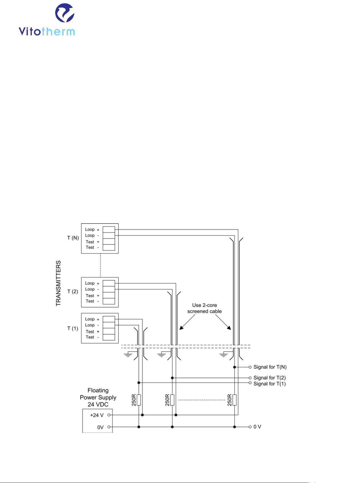
Connection and Wiring
Transmitters are designed for standard two-wire operation where the output is
supplied via the same wire pair as the power supply. The external circuit loop is
connected to the transmitter PCB via a screw terminal connector. Schematic
Wiring Diagram for 4-20 mA Transmitters
Instruction and operating guideline CO-detector
Type:
VCD2 CO-Detector
5
Power Supply and Total Loop Resistance
Transmitters can be operated with any single-sided power supply within the
range 10 - 35 VDC. However the power supply used will impose constraints on
the total loop resistance in the external circuit, and this must be taken into
account when choosing the supply voltage. This includes the measuring resistor
at the remote receiver and any meters for calibration etc. The example below
illustrates the relationship between the two considerations.
So that the sensor only requires a few seconds to settle after start-up, the
transmitter circuit has an FET powered shorting link between the sensing and
reference electrodes of the CiTiceL when left unpowered. However, due to the
different operating nature of biased sensors (which include nitric oxide and
hydrogen chloride sensors), this link is omitted with these transmitters. They
therefore require a longer start-up time when first powered, and must remain
powered continuously in the actual application.
IMPORTANT : The transmitter is designed for power supplies within the range
10 - 35 VDC only. Connection to mains electricity will result in transmitter failure.
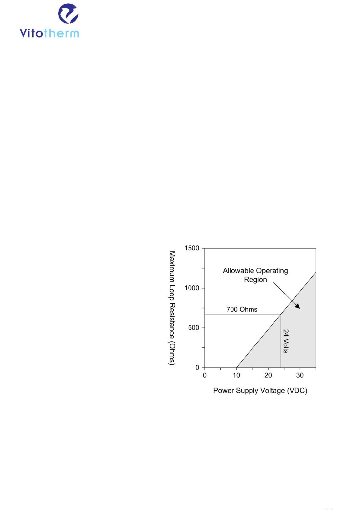
Relationship Between Power Supply Voltage and Total Loop Resistance
Example : Using a transmitter with a standard 24 VDC power supply, the total
allowable resistance is as follows:
The minimum voltage required at
the transmitter for operation is 10
Volts. Therefore, the maximum
drop allowed due to loop resistance
is 14 Volts.
Full scale deflection current
requirement : 20 mA
Therefore, the maximum loop
resistance allowable
(using Ohm's law):
R = V / I
R = (14 x 1000) / 20
R = 700 Ohms
In this case, a measuring resistor of 250 Ohms is appropriate, giving a scale of 1
V to 5 V.
Instruction and operating guideline CO-detector
Type:
VCD2 CO-Detector
6
Calibration Guidelines
CiTiceL transmitters are supplied precalibrated, and
the sensitivity of the device should not drift by more
than 2% of full signal per month. The circuit board
has a single push button which can be used to
calibrate the transmitter should this be required.
The standard mounting system allows easy aspiration
using the calibration plug provided. With the plug in
place and sealing caps fitted, the CiTiceL is
completely isolated from the atmosphere. With sealing caps removed, calibration
gas can be supplied through one inlet and exhausted through the other.
Calibrating to Cross Sensitive Gases
Electrochemical CiTiceLs are cross sensitive to certain non-target gases.
Information regarding cross sensitivities for particular sensors can be found on
the product datasheets. It is important to remember however, that cross
sensitivity data is only very approximate and cross sensitivities will vary between
sensors and sensor batches. Therefore, it is not advisable to calibrate sensors or
transmitters to non-target gas as this will result in a degree of measurement
error.
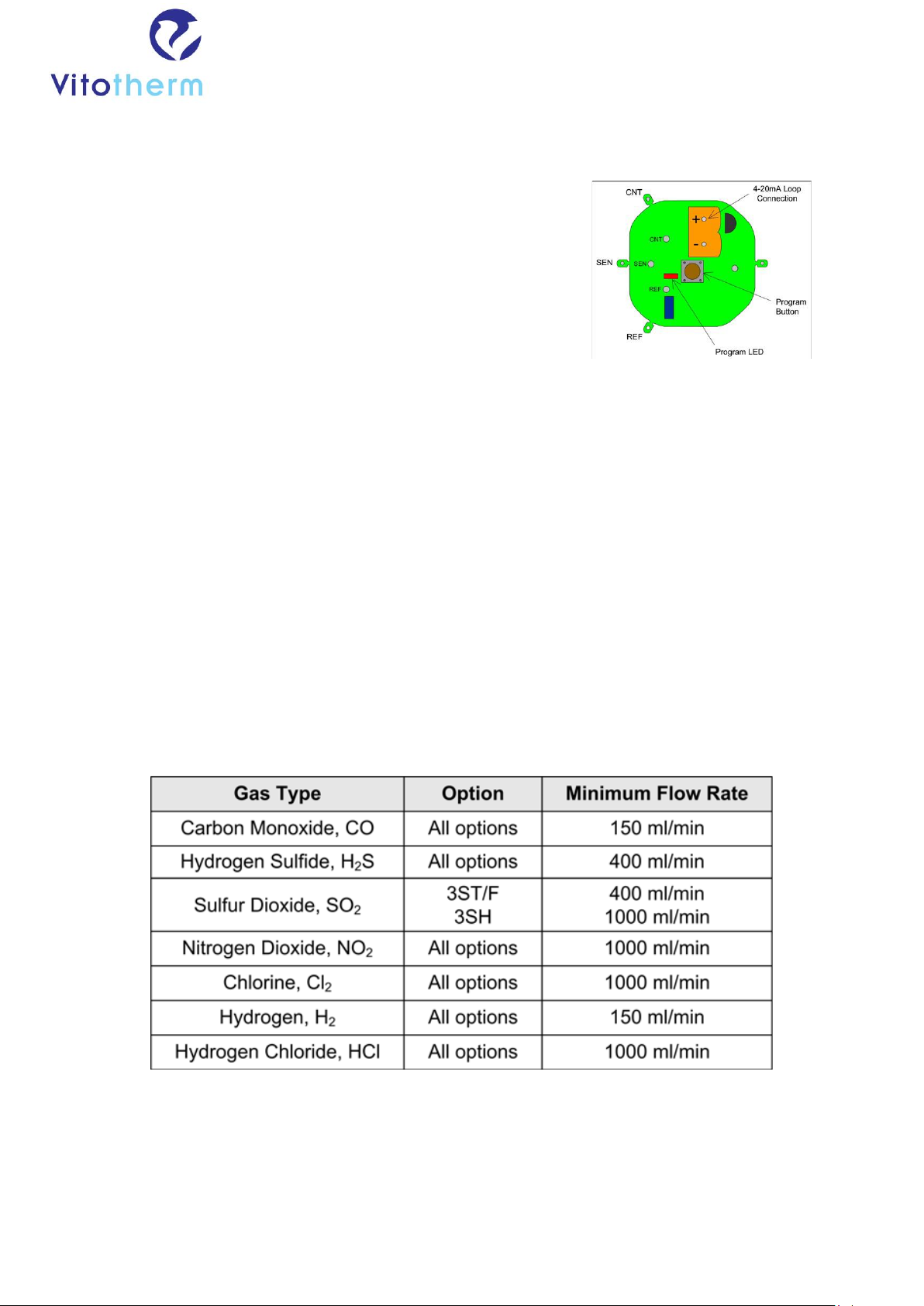
Recommended Gas Flow Rates
A minimum flow rate is required to ensure accurate calibration - it also means
that the response from a CiTiceL is equivalent in configurations where gas is
flowing over the sensor and those where the sample is allowed to diffuse into the
sensor. The minimum flow rate which is required will be different depending on
the CiTiceL type –these are shown in the table below.
These flow rates are based on gas delivery apparatus used at City Technology
Ltd. Other designs of gas delivery may have an influence on the flow rates
required. EasyCal Circuit Board Layout
Standard User Calibration Method (Span Gas = 20 mA Signal)

Instruction and operating guideline CO-detector
Type:
VCD2 CO-Detector
7
1. Connect loop power to the transmitter.
2. Apply clean air or an inert gas to the transmitter for 2 minutes.
3. Hold down the program button until the LED flashes at approximately 1 Hz.
The 4 mA level is now set.
4. Apply the required span gas to the transmitter for 2 to 5 minutes.
5. Press and release the program button. The 20 mA level is now set to
represent the concentration of the calibration gas used.
6. The LED will flash at approximately 8 Hz for 8 Seconds. This is the timeout
period.
7. Calibration is complete. The LED will clear and the transmitter will return to
normal mode.
Non-Standard Span Gas Calibration Methods
Span Gas Within ±5% of Full Range
1. Calculate the mA signal expected for span gas. The output range available
is 19.2 mA to 20.8 mA.
Example
Required 4-20 mA range is 0-500 ppm
Available span gas is 480 ppm
Dynamic Range is 16 mA
Therefore, 1 mA = 31.25 ppm
Expected signal at 480 ppm = (15.36 mA + 4 mA) = 19.36
mA
2. Connect loop power to the transmitter.
3. Apply clean air or an inert gas to the transmitter for 2 minutes.
4. Hold down the program button until the LED flashes at approximately 1 Hz.
The 4 mA level is now set.
5. Apply the required span gas to the transmitter for 2 to 5 minutes.
6. Press and hold the program button to set the 20 mA level.
7. The LED will flash at approximately 8 Hz for 8 Seconds. Continued momentary
pressing of the program button during this timeout period will increase the
output by 40 μΑ per press. When the output reaches 20.8 mA, the next button
press will take the output to 19.2 mA. Further button presses will again increase
the output by 40 μΑ When the required output is reached, allow the transmitter
to time out.
8. Calibration is complete. The LED will clear and the transmitter will return to
normal mode.

Instruction and operating guideline CO-detector
Type:
VCD2 CO-Detector
8
Span Gas not within ±5% of Full Range
Note : A current source is required for this procedure.
1. Apply a gas of known concentration to the sensor for 2 to 5 minutes.
2. Measure the current from the sensor. This can then be used to calculate
the sensitivity (in μΑ/ppm) for the specific sensor being calibrated (see
step 3).
3. Calculate the expected current when the sensor is exposed to the full
scale of target gas.
Example
Required 4-20 mA range is 0-500 ppm
Available span gas is 300 ppm
Current from sensor when exposed to span gas = 33 μΑ (from step 2)
Therefore, sensitivity = (33 μΑ/ 300 ppm) = 0.11 μΑ/ppm
Expected signal at 500 ppm = (0.11 μΑ/ppm x 500 ppm) = 55 μΑ
4. Connect the current loop power to the transmitter
5. Connect the current source to the transmitter.
or Oxidising Sensors (CO, H2S, SO2, NO ...) Connect the negative to 'SEN'
and the positive to 'CNT'. Connect 'CNT' and 'REF' together. For Reducing
Sensors (CL2, NO2 ...). Connect the negative to 'CNT' and the positive to
'SEN'. Connect 'CNT' and 'REF' together.
6. Set the current source to zero.
7. Hold down the program button until the LED flashes at approx. 1 Hz (4 mA
level now set in RAM).
8. Set the current source to the value calculated for the full scale of target
gas (from step 3).
9. Press and release the program button (20 mA level now set in RAM).
10.The LED will flash at approximately 8 Hz for 8 Seconds. This is the timeout
period.
11.Calibration is complete. The LED will clear and the transmitter will return
to normal mode.
Important Notes
Recalibration is only possible if the output of the sensor at full scale is greater
than 50% of the original factory calibration. Failure can occur if:
1. Attempt is made to recalibrate to a range less than 50% of the original
calibrated range.
2. The output of the sensor has fallen by more than 50%. In this case, the
sensor must be replaced.
3. Incorrect span gas is used.
4. Insufficient time is allowed for the output to settle after exposing the sensor
to span gas. Span gas should be applied for 2-5 minutes before setting the 40
mA level.

Instruction and operating guideline CO-detector
Type:
VCD2 CO-Detector
9
Transmitter Error Condition
Any time the error condition is set, the output will be forced to 21 mA and the
LED will be held on. Carry out the Reset function to reset the sensor.
Reset to Factory Calibration
1. Remove loop power from transmitter.
2. Hold down the program button and connect loop power to transmitter.
3. The LED will blink as soon as power is applied (approx. 2 Hz). The
transmitter output is now set to 21 mA.
4. Releasing the program button will start an 8 second timeout period.
5. After 8 seconds, the factory calibration will overwrite the user calibration.
6. The LED will clear and the transmitter will return to normal mode.
Handling and Storage
Electrochemical sensors are relatively insensitive to mishandling. Following the
simple guidelines given below should ensure correct operation.
Sensors may be stored for up to six months. They should be kept sealed in the
containers in which they were supplied in clean dry air at 0 - 20°C.
Sensors should not be stored in areas containing solvent vapours. All
electrochemical sensors are unsuitable for use in applications where organic
solvent vapours are present as exposure may inhibit performance.
Sensors must not be subjected to any pressure when handling or clamping.
MSDS’s can be provided for all City Technology products, detailing their
hazardous content. The hazardous waste disposal regulations depend on
geographic location, and local regulations should be checked before discarding
the sensors.
WARNING: By the nature of the technology used, any electrochemical or
catalytic bead sensor can potentially fail to meet specification without warning.
Although City Technology makes every effort to ensure the reliability of our
products of this type, where life safety is a performance requirement of the
product, and where practical we recommend that all sensors and instruments
using these sensors are checked for response to gas before use

Instruction and operating guideline CO-detector
Type:
VCD2 CO-Detector
10
Every effort has been made to ensure the accuracy of this document at the time of printing. In accordance
with the company’s policy of continued product improvement City Technology Limited reserves the right to
make product changes without notice. No liability is accepted for any consequential losses, injury or damage
resulting from the use of this document or from any omissions or errors herein. The data is given for guidance
only. It does not constitute a specification or an offer for sale. The products are always subject to a
programme of improvement and testing which may result in some changes in the characteristics quoted. As
the products may be used by the client in circumstances beyond the knowledge and control of City Technology
Limited, we cannot give any warranty as to the relevance of these particulars to an application. It is the
clients’ responsibility to carry out the necessary tests to determine the usefulness of the products and to
ensure their safety of operation in a particular application.
Performance characteristics on this data sheet outline the performance of newly supplied sensors. Output
signal can drift below the lower limit over time.
9.2 Technical instruction manual service technicians
Clip numbers Crouzet M3:
Input: output:
+ 24 VDC 01 three-way valve measurement flue gas
- 24 VDC 02 output alarm red light
I1 enable controls 03 safety circuit burner ok
I2 start CO2 demand 04 pump activated
I3 pump pressure present 05 chimney valve open (make
contact in centre)
I4 selection text CO2 vent activated instead of
RGK activated 06 chimney valve closed (when desired
with CO2 vent activated)
I5 ES6 chimney valve not closed 07 alarm potential-free (make contact
in centre)
I6 not in use 08 no alarm potential-free
IB 0-10V input CO sensor
IC not in use
ID reset
IE not in use
Description VCD2 Programme:
After enabling the controls and start of CO2 demand at input l1 and l2, the pump
will be activated. The pressure switch will get a 10 second window to build up
pressure. After a delay-time the three-way valve will activate and flue gasses will
be measured. When U5 increases, the fan or chimney valve will be activated.
After losing the demand for CO2, l1 and l2, U5 (chimney valve) and U1 (3-way
valve) will switch over and after the flush time U4 (pump) will switch off. After
the delay of the chimney valve, approx. 5 minutes, l5 should be present. When
l5 is not present, l4 will switch off (safety circuit burner ok) and so will the MY2
relay. The contacts of the MY2 relay are connected to 3 terminals as a potential
free contact which can, subsequently, be connected to the safety circuit of the
burner.
In the following situations a fault and immediate shutdown will take place:
1. Pump pressure not present; U5/6 and U7/8 and U2 will switch over. The
three-way valve is activated for 2 min. (flushing).
2. CO too high after a delay-time of 1 minute, the display will show 'CO too
high'. U5/6 and U7/8 and U2 will switch over. The three-way valve is activated
for 2 min. (flushing).
3. Sensor signal not present (4 mA not present)
Table of contents
Popular Gas Detector manuals by other brands


BEINAT
BEINAT BXI32 Installation and user guide

ATI Technologies
ATI Technologies PortaSens III D16 O & M Manual

Electronics
Electronics Ei413 quick start guide

Blackline Safety
Blackline Safety G7 BRIDGE Technical user's manual

Tecnocontrol
Tecnocontrol TS282E Series user manual

seeed studio
seeed studio Grove MQ3 manual