ATI Technologies PortaSens III D16 User manual

O & M Manual
PortaSens III
Portable Gas Leak Detector
Home Office European Office
Analytical Technology, Inc. ATI (UK) Limited
6 Iron Bridge Drive Unit 1 & 2 Gatehead Business Park
Collegeville, PA 19426 Delph New Road, Delph
Phone: 800-959-0299 Saddleworth OL3 5DE
610-917-0991 Phone: +44 (0)1457-873-318
Fax: 610-917-0992 Fax: + 44 (0)1457-874-468
Web: www.Analyticaltechnology.com

PortaSens III Portable Gas Leak Detector, Model D16
Operation and Maintenance Manual
Rev-C Apr 2020
Table of Contents
SPECIFICATIONS......................................................4
REFERENCE DRAWINGS .............................................5
INTRODUCTION ......................................................8
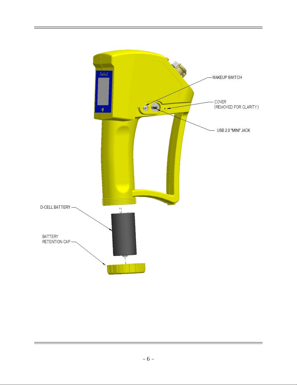
D16 PORTASENS III.................................................8
Inlet and Outlet Ports.........................................8
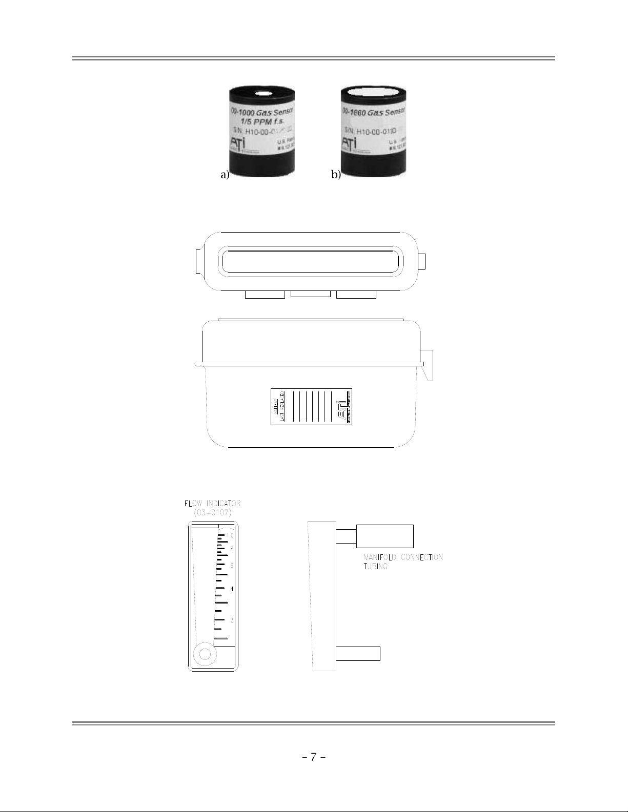
H10 SENSOR ..........................................................9
Electro-chemical Cell Versions ...........................9
Installing the Sensor...........................................9
OPERATION ..........................................................10
STARTUP..............................................................10
SHUTDOWN..........................................................11
MAIN DISPLAY......................................................11
Gas Reading, Units, Name, and Temperature .11
Gas Alarm Indicators .......................................12
Meter ...............................................................13
Battery Indicator..............................................13
Status Messages ..............................................13
Date and Time .................................................14
Display Background .........................................14
Buttons.............................................................14
MAIN MENU ........................................................15
DISPLAY...............................................................15
Brightness ........................................................15
Main Display Appearance................................16
Menu Timeout .................................................17
Sleep Mode ......................................................17
Troubles ...........................................................17
Configuring the Display....................................18
ALARMS ..............................................................21
Danger Alarm...................................................22
Warning Alarm ................................................22
Caution Alarm..................................................22
Configuring Alarms ..........................................23
DATA LOG............................................................24
USB Mode ........................................................24
Directory Structure...........................................25
File Structure....................................................26
Configuring the Data Logger ...........................27
PUMP .................................................................28
Pump Status.....................................................28
Configuring the Pump ......................................29
SENSOR...............................................................30
Range...............................................................31
Blanking ...........................................................31
Averaging.........................................................32
Configuring the Sensor.....................................32
Calibration .......................................................34
Factory Calibration Services.............................34
Owner Calibrations ..........................................35
Pressurized Gas Sources...................................35
Sensor Calibration Steps ..................................36
Calibration History ...........................................37
H10 Sensor Response Times.............................40
Gas Interferences .............................................41
Response Test ..................................................43
H10 Sensors and D12 or F12 Transmitters.......44
SYSTEM............................................................... 44
System “About” Page.......................................44
Date and Time .................................................44
Auto-shutdown ................................................44
Sound ...............................................................45
Default Settings ...............................................45
Configuring System Settings ............................45
TIMED SAMPLING..................................................49
Description.......................................................49
Operation.........................................................49
Configuring Timed Sampling............................51
POWER ...............................................................52
NiMH Battery...................................................52
USB Power .......................................................52
Shutdown.........................................................52
MAINTENANCE..................................................... 53
INTAKE FILTER ......................................................53
BATTERY CONTACTS............................................... 53
TROUBLES AND EXCEPTIONS................................ 54
TROUBLE MESSAGES.............................................. 54
PUMP TROUBLES...................................................55
OTHER TROUBLES.................................................. 56
GENERAL CORRECTIVE ACTIONS................................ 57
EXCEPTION MESSAGES ........................................... 58
SPARE PARTS........................................................ 60
H10 GAS SENSOR MODULES ...................................61

PortaSens III Portable Gas Leak Detector, Model D16
Operation and Maintenance Manual
Rev-C Apr 2020
Table of Figures
Figure 1. PortaSens III, front view. _________________________________________________________________ 5
Figure 2. PortaSens III, rear view. __________________________________________________________________ 5
Figure 3. PortaSens III, right side view.______________________________________________________________ 6
Figure 4. H10 gas sensor module (ordered separately). ________________________________________________ 7
Figure 5. Sensor Keeper. _________________________________________________________________________ 7
Figure 6. Flow meter. ___________________________________________________________________________ 7
Figure 7 Model D16, PortaSens III Gas Leak Detector. _________________________________________________ 8
Figure 8. H10 "Smart Sensor" module. ______________________________________________________________ 9
Figure 9 Sensor Keeper. _________________________________________________________________________ 9
Figure 10 D16 startup displays. __________________________________________________________________ 10
Figure 11 Main Display page indications (example) __________________________________________________ 11
Figure 12 Data log control button ________________________________________________________________ 14
Figure 13 Adjusting brightness by swiping. _________________________________________________________ 15
Figure 14 Meter styles - Normal (a), and % FS (b).____________________________________________________ 16
Figure 15 USB mode display. ____________________________________________________________________ 24
Figure 16 Data logger file structure. ______________________________________________________________ 25
Figure 17 Example data log file opened with Microsof Excel. __________________________________________ 26
Figure 18 Pump status on “Main Display”. _________________________________________________________ 28
Figure 19 Sensor Information page. ______________________________________________________________ 30
Figure 20. Gas source connection. ________________________________________________________________ 35
Figure 21 System About page. ___________________________________________________________________ 44
Figure 22 Trouble page. ________________________________________________________________________ 54

PortaSens III Portable Gas Leak Detector, Model D16
Operation and Maintenance Manual
Rev-C Apr 2020
SPECIFICATIONS
Gas Sensor H10 “Smart Sensor” gas Modules, ordered separately
Range Sensor Dependent (see H10 Gas Sensor Modules on page 61, or
contact the manufacturer)
Display Backlighted, resistive touch-sensitive, 320x240 color graphics LCD with
an anti- glare overlay. Custom overlay and graphic logo available.
Accuracy Sensor dependent (typically ± 5% of value, limited by cal. gas)
Sensitivity 1% of (lowest) sensor module range
Repeatability ± 1% of (lowest) sensor module range
Sampling Pump Internal diaphragm pump, 400 cc/min (0.85 SCFH), adjustable. Long life,
variable speed, DC motor
Alarms Three level alarms, configurable for high or low operation, or disabled
Trouble, low battery, restricted flow alarms. Alarm indications on LCD
and beeper
Data Logger Internal 4Gb
Selectable sampling intervals from 10 seconds to 60 minutes
Sample/Measure Self-timed sample/measure mode for repeatable readings
Real-Time Clock Battery backed, accurate to approximately 1 minute per year
Input/Output USB 2.0 MSD Class interface with 1m mini-USB cable
Power D-cell battery, rechargeable*, NiMH, 10,000mAH
10-12 hours continuous operation
90 days shelf-life (fully charged, no sensor)
May also use non-rechargeable, D-cellalkaline
*External charger required (available option)
Note: USB connection provides power, but does not charge battery
Sound Inter beeper
Operating Temp. -25º to +60º C
Humidity 0-95% Non-condensing
Construction Glass filled nylon, PVC, and stainless steel
Shipping Weight 4.9 lbs / 2.22 kg (complete package)

PortaSens III Portable Gas Leak Detector, Model D16
Operation and Maintenance Manual
Rev-C Apr 2020
Reference Drawings
Figure 1. PortaSens III, front view.
Figure 2. PortaSens III, rear view.

PortaSens III Portable Gas Leak Detector, Model D16
Operation and Maintenance Manual
Rev-C Apr 2020
Figure 3. PortaSens III, right side view.

PortaSens III Portable Gas Leak Detector, Model D16
Operation and Maintenance Manual
Rev-C Apr 2020
Figure 4. H10 gas sensor modules (sold separately)
a) Electrochemical, b) Infrared
Replace Battery every Six (6) Months
00-0981 H10 Sensor Keeper
Figure 5. Sensor Keeper (not for use with infrared sensors).
Figure 6. Flow meter.

PortaSens III Portable Gas Leak Detector, Model D16
Operation and Maintenance Manual
Rev-C Apr 2020
H10 Sensor
Figure 8. H10 "Smart Sensor"
module.
H10 Sensor Cells
Electro-chemical cell based sensors should
be stored in the Sensor Keeper to maintain
bias. Never store infrared cell based
sensors in the Sensor Keeper.
Installing the Sensor
Figure 9 Sensor Keeper.

PortaSens III Portable Gas Leak Detector, Model D16
Operation and Maintenance Manual
Rev-C Apr 2020
OPERATION
D16 pages are normally presented on a dark background. Pages
depicted below appear on a white, or light colored background to improve
readability.
Startup
LCD and CPU revision levels and serial number.
Times out after four seconds. Swipe down to advance
without waiting (image will not match your device).
Information about the currently installed sensor.
Times out in four seconds. Swipe down to
advance without waiting (image will not match
your device)
Main operational display, presents the gas
level reading, gas temperature, alarm
indicators, battery and pump status, date,
and time (example only).
Figure 10 D16 startup displays.
LCD Rev 1.0
Model-Rev-S/N

PortaSens III Portable Gas Leak Detector, Model D16
Operation and Maintenance Manual
Rev-C Apr 2020
Shutdown
Main Display
Figure 11 Main Display page indications (example)
Gas Reading, Units, Name, and Temperature
Range
maximum
Averaging
Date and time
Battery indicator
Status messages
Gas temperature
Meter
Gas reading
Gas units of measure
Alarm name
Off button
Menu button
Log on/off
button
Display background
Alarm and
over-range
indicator
Gas name
(symbol)
Danger alarm level
Warning alarm level

PortaSens III Portable Gas Leak Detector, Model D16
Operation and Maintenance Manual
Rev-C Apr 2020
Blanking
Table 1 Gas reading resolution.
Gas Alarm Indicators
Danger Warning
Caution only
Table 2 Alarm indicators.
Alarm Name
Priority (ranking)
Indicator
(RED)
Highest
Alarm type = “HIGH”
Alarm type = “LOW”
(YELLOW)
Middle
(not displayed when
danger alarm is active)
Alarm type = “HIGH”
Alarm type = “LOW”
(BLUE)
Lowest
(not displayed when
danger or warning
alarm is active)
Alarm type = “HIGH”
Alarm type = “LOW”
Range
Resolution
0.00 to 4.99
0.01
5.0 to 49.9
0.1
50 and above
1

PortaSens III Portable Gas Leak Detector, Model D16
Operation and Maintenance Manual
Rev-C Apr 2020
Meter
Battery Indicator
Table 3 Battery indications.
Indication
Description
Hours
Remaining*
(NiMH)
Bat>=1.25v
10 - 11
Bat=1.20-1.24v
Bat=1.15-1.19v
5 - 6
Bat=1.10-1.14v
Bat=1.05-1.09
Low
Bat<1.05
Shutdown
imminent
Device powered by USB
connection (battery disabled)
*Starting from fully charged state, as instructed by the supplied (optional) charger.
Status Messages
Table 4 Main display status messages.
Message
Description
BATTERY LOW
Battery life down to one bar
NO BATTERY
Battery removed (only appears in normal operation running on
USB power)
CHECK FLOW
Sampling wand or pump restricted
PUMP OFF
Pump motor disabled via configuration setting
NO PUMP
Pump motor enabled but pump current not detected

PortaSens III Portable Gas Leak Detector, Model D16
Operation and Maintenance Manual
Rev-C Apr 2020
Main Display Appearance
Figure 14 Meter styles - Normal (a), and % FS (b).
types levels
Table 5 Alarm setting rules for “Normal” meter presentation.
Rules
Comments
1
Danger Alarm Type = High
and
Warning Alarm Type = High
and
Danger Alarm Level > Warning Alarm Level
Typical of toxic gas sensors.
2
Danger Alarm Type = Low
and
Warning Alarm Type = Low
and
Danger Alarm Level < Warning Alarm Level
Typical of oxygen sensors.

PortaSens III Portable Gas Leak Detector, Model D16
Operation and Maintenance Manual
Rev-C Apr 2020
Configuring the Display
Table 6 Configuring the display.
Description
Display
Display Menu
On the “Main Display” page, touch the “Menu”
button, and then touch the “Display” button. This
will present the “Display Menu” page, as shown on
the right.
Display Brightness
On the “Display Menu” page, touch the “Bright”
button. The numeric keypad control will appear
and display the current value, as shown on the
right. The value represents the default brightness
–only if it has not been adjusted by swiping. It is
suggested to adjust the brightness by swiping
before entry, then save the new value by touching
“Ok” button. Touch the “Back” button to close the
control and return without saving.
Setting range: 1(dark) - 15 (light)

PortaSens III Portable Gas Leak Detector, Model D16
Operation and Maintenance Manual
Rev-C Apr 2020
Description
Display
Main Display Background
On the “Display Menu” page, touch the “Main
Display” button, and then touch the “Back-Color”
button. The “spin” edit control will appear and
display the current value, as shown on the right.
Touch the up or down arrow to change the setting,
then touch the “Ok” button to save it. Touch the
“Back” button to close the control and return
without saving.
Setting range:
•Dark –(default) better for indoor and
night use.
•Light –better for outdoor use
Main Display Meter
On the “Display Menu” page, touch the “Main
Display” button, and then touch the “Meter” button.
The “spin” edit control will appear and display the
current value, as shown on the right. Touch the up
or down arrow to change the setting, then touch the
“Ok” button to save it. Touch the “Back” button to
close the control and return without saving.
Setting range:
•Normal –(default) three-colored style
showing the Danger and Warning alarm
levels (when allowed by alarm settings).
•% FS –simple style presenting the full
scale range, ½ full scale range, and 0.

PortaSens III Portable Gas Leak Detector, Model D16
Operation and Maintenance Manual
Rev-C Apr 2020
Description
Display
Main Display Temp Units
On the “Display Menu” page, touch the “Main
Display” button, and then touch the “Temp Units”
button. The “spin” edit control will appear and
display the current value, as shown on the right.
Touch the up or down arrow to change the setting,
then touch the “Ok” button to save it. Touch the
“Back” button to close the control and return
without saving.
Setting range:
•°F
•°C
Menu Timeout
On the “Display Menu” page, touch the “Menu
Timeout” button. The numeric keypad control will
appear and display the current value, as shown on
the right. Use the keypad to enter the new value,
then touch the “Ok” button to save it. Touch the
“Back” button to close the control and return
without saving.
Setting range: 1-60 minutes
Sleep
On the “Display Menu” page, touch the “Sleep”
button. If there are no gas level alarms active,
the display will turn off, but the D16 will continue
to function.
Setting range:
•Wake on alarm
•No wake on alm
If “Wake on alarm” is selected, and an alarm is
active, an exception message will be displayed.
This manual suits for next models
2
Table of contents
Other ATI Technologies Gas Detector manuals