Oldham MX62 User manual

I
In
ns
st
ta
al
ll
la
at
ti
io
on
n
a
an
nd
d
U
Ut
ti
il
li
is
sa
at
ti
io
on
n
m
ma
an
nu
ua
al
l
G
G
A
A
S
S
D
D
E
E
T
T
E
E
C
C
T
T
I
I
O
O
N
N
S
S
Y
Y
S
S
T
T
E
E
M
M

3
OLDHAM SA
GAS AND FLAME DETECTION
STACK GAS AND DUST MONITORING
We thank you for choosing an OLDHAM SA instrument.
We have taken every step to ensure that this equipment continues to
give you complete satisfaction.
Please read the instruction manual carefully before using the instru-
ment.

4
LIMITS OF RESPONSIBILITY
* OLDHAM SA hereby rejects any and all responsibility with regard to any person for
material damage, bodily injury or death resulting in whole or in part from the inappropri-
ate use, installation or storage of its equipment not conforming to the instructions and to
warnings and/or not conforming to standards and regulations in force.
* OLDHAM SA does not allow or authorize any company, person or legal entity to as-
sume such responsibility on the part of OLDHAM SA, even if involved in the sale of the
products of OLDHAM SA.
* OLDHAM SA shall not be liable for any direct or indirect damage, or any direct or indi-
rect legally awarded damages resulting from the sale and use of any of its products,
UNLESS THOSE PRODUCTS WERE SPECIFIED AND CHOSEN BY OLDHAM
SA FOR THE USE MADE OF THEM.
OWNERSHIP CLAUSES
* Sketches, drawings, specifications and data included herein contain confidential informa-
tion which is the property of OLDHAM SA.
* These information shall not be, in part or in whole, physically, electronically or in any
other form whatsoever, reproduced, copied, divulged, translated, used as a basis for the
manufacture or sale of OLDHAM SA equipment or used for any other reason without
the prior approval of OLDHAM SA.
WARNINGS
* This document is not a contractually binding document, OLDHAM SA reserves the right
to make any changes, without notice, to the technical characteristics of its equipment in
order to improve performance levels, in the interest of its customers.
* CAREFULLY READ THE INSTRUCTIONS BEFORE ALL FIRST USE:
This instruction manual must be read by any person who is, or will be, responsible for the
use, maintenance or repair of this equipment.
* This equipment will conform with the specified performance levels only if it is used,
maintained and repaired in accordance with the directives of OLDHAM SA and by
OLDHAM SA personnel or personnel authorized by OLDHAM SA.

5
C
CO
ON
NT
TE
EN
NT
TS
S
1. THE SYSTEM WINPRO®......................................................................7
1.1. THE MX62 SYSTEM BRIEFLY ................................................................................8
1.2. THE MX62 SYSTEM SYNOPSE ...............................................................................9
1.3. MX62 SYSTEM : FUNCTIONAL DRAWING........................................................10
2. CONFIGURATION ...............................................................................11
2.1. DESCRIPTION OF MODULES................................................................................12
2.1.1. Controller Module (CM) ..............................................................................12
2.1.2. Analog Input Module (AEM).......................................................................13
2.1.3. LED Module.................................................................................................14
2.1.4. Basic Relay Module (RBM) and Extension Relay Module (REM).............15
2.1.5. Analog Output Module (AAM)....................................................................17
2.1.6. LCD Module.................................................................................................18
2.1.7. Logo Module................................................................................................18
2.1.8. Adapter module (numeric loop)...................................................................19
2.2. DESCRIPTION OF REDUNDANCY.......................................................................20
2.3. DESCRIPTION OF CONTROL PANEL..................................................................20
3. OPERATION OF THE SYSTEM WINPRO®.....................................21
3.1. CHANNEL AND SYSTEM INFORMATION .........................................................21
3.2. CONNECTING STATUS ..........................................................................................23
3.3. NORMAL OPERATION...........................................................................................23
3.3.1. Normal Status ...............................................................................................23
3.3.2. Channel Malfunction....................................................................................23
3.3.3. Insufficient Signal ........................................................................................24
3.3.4. Alarms ..........................................................................................................24
3.3.5. Excess of Measuring Range .........................................................................24
3.3.6. Resetting of Alarm Signals...........................................................................24
3.4. MAINTENANCE MODE..........................................................................................25
3.4.1. Forcing of the alarm relays into "out of alarm" position...........................26
3.4.2. Operational Test...........................................................................................27
3.4.3. Calibration....................................................................................................27
3.4.4. Channel On/Off ............................................................................................27
3.4.5. PC Communication ......................................................................................28
3.5. SINGLE MODE.........................................................................................................28
3.6. SYSTEM FAILURE ..................................................................................................28
3.7. MEASURES AGAINST FAULTS............................................................................29
4. OPERATING OF LCD MODULE........................................................30
4.1. DISPLAY OF CHANNELS.......................................................................................30
4.2. MENU........................................................................................................................31
4.2.1 Functions of the four LCD Key Buttons ......................................................31
6
5. MAINTENANCE ...................................................................................32
5.1. CALIBRATION AND ADJUSTMENT....................................................................32
5.1.1. Direct Calibration at the Transducer ............................................................32
5.1.2. Remote Calibration for Standard Transducers.............................................32
5.1.3. Automatic Calibration of Transducer TBGW EX........................................33
5.1.4. Remote Calibration of Transducer TBGW EX ............................................33
5.2. TYPE AND COMPOSITION OF TEST GAS ..........................................................33
6. TECHNICAL DATA..............................................................................34
7. TERMINAL CONNECTIONS, JUMPERS AND ROTARY SWITCH......35
7.1. CONTROLLER MODULE (CM)..............................................................................35
7.2. ANALOG INPUT MODULE (AEM)........................................................................37
7.3. BASIC RELAY MODULE (RBM) AND EXTENSION RELAY MODULE (REM)
38
7.4. ANALOG OUTPUT MODULE (AAM) ...................................................................39
7.5. LCD MODULE ..........................................................................................................40
7.6. LED MODULE ..........................................................................................................41
7.7. LCD COPY MODULE ..............................................................................................43
7.8. LOOP MODULE (LOOPM)......................................................................................44
8. CONNECTION AND INSTALLATION ..............................................43
8.1. WIRING .....................................................................................................................43
8.1.1. Mains Supply................................................................................................43
8.1.2. Connection of Relays ...................................................................................43
8.1.3. Connection of Transducers...........................................................................43
8.2. INSTALLATION OF THE WINPRO® ....................................................................53
8.2.1. Wall-mounted Housing ................................................................................53
8.2.2. 19"-Rack.......................................................................................................53
8.2.3. Control Panel................................................................................................53
9. ACCESSORIES......................................................................................54
10. APPROVALS .........................................................................................54
10.1. CE MARKING...........................................................................................................54
10.2. METROLOGICAL APPROVAL..............................................................................54
11. LOGICOM 62 SOFTWARE..................................................................56
Starting COM 62..................................................................................................................56
DETECTOR SETTINGS.....................................................................................................66
Configuration of Relays.......................................................................................................72
Configuration of Analog Outputs ........................................................................................75
Datalogger and LinePrinter Settings....................................................................................83
Upload / Download..............................................................................................................84

7
1.The System WinPro®
The system WinPro® is a stationary gas control unit to be used in combination
with a variety of transducers for continuous detection of combustible and toxic
gases.
Main features are high reliability as well as remarkable flexibility. This flexibil-
ity refers to all areas, such as free programmability and placing of relays and
analog outputs as well as optional installation in wall-mounted housings, 19”-
racks or control panels.
Modular components allow extension of up to 64 channels, 128 re-lays and 64
analog outputs as well as optional use of an LCD module with data logger plus
process and field bus module, making the gas detection system suitable for all
applications.
The complete system and all required modifications can be set by means of the
software ConfigPro.

8
1.1.The MX62 system briefly
MX 62 /® WinPro
For 64 detectors maximum
Central unit, with redundant controllers, composed of :
•main module, CPU with 2 processors
•Panel* with alarm LED(s) and keyboard
Input side :
•Analogic modules with 8 x 4-20 mA inputs (included a RS485 link up to the
detectors for auxiliary data)
•Loop modules* for 16 addresses or 8 numeric adressable detectors and 8
analogic detectors directly connected to the module
Output side :
•Modules* for 8 analogic outputs 4-20 mA
•Modules* for 8 or 16 relays with SPDT outputs
Auxiliaries :
•Display alphanumeric panel* with optional module for data storage
•Communication module non redundant, with RS232 port OWNER format, or
RS485 PROFIBUS or MODBUS1, for export of data to alarm supervision.
•Communication1module redundant, with 2 RS485 ports PROFIBUS for ex-
port of data to securized supervisor.
•Printer (optional)
INTERFACES
•Assistance software for configuration
•Alarm supervision software (optional)
1Will be developped for 2002
* (on distance) : connected to CPU via the specific internal safety bus RS485 and consequently able to be ex-
ported following the needs relative to the limits of equipment specifications of the RS485

9
1.2.The MX62 System synopse
DelPanel LCD Panel + events memory Distant LCD Panel
ANALOG. MODULE
4/20 mA
Controller B
Controller A
REDUNDANT PROFIBUS MODULE
RELAYS MODULES
OUTPUTS MODULES
4/20mA
INPUT ADAPTER MODULE FOR
TRANMITTERS
ANALOG. MODULE
4/20mA
Centronics printer
interface
RS232 control interface
Plant format
Auxiliaries interfaces
RS485 converted output
MODBUS or PROFIBUS formats
On field Bus

10
1.3.MX62 system : functional drawing
INPUTS DETECTORS OUTPUTS
128 relays / 64 analog.
T
TH
HE
E
S
SY
YS
ST
TE
EM
M
Local modules
Remote modules
Input module I
4..20 mA analog. + RS 485
(maintenance)
Module II
4..20 mA analog. + RS 485
(maintenance)
Module VI
4..20 mA analog. + RS 485
(maintenance)
Controller A
Controller B
Central unit (CPU)
Controller module
Module
1 to 8 / 8 to 16 relays
Modules for analog
1 to 8 (outputs)
Input adapter module
for digit./ana.
transmitters
2xRS485
Redundant profibus
module com.
Input module
for analog.
Transmitters
4…20 mA

11
2.Configuration
The system consists of a controller module plus various other modules linked by
digital bus. Basic configuration is as follows:
•Analog Input Module (AEM)
•Controller Module (CM)
•LED Module
The analog input module converts the 4-20mA of the transducers into digital bus
signals to be transmitted to the controller module where these are evaluated and
separately indicated for each channel according to the respective presetting. One
analog input and one LED module are provided for eight channels each. The
controller module can directly be employed for 64 channels.
In addition, further modules can be integrated into the system as required:
•Basic Relay Module (RBM)
•Extension Relay Module (REM)
•Analog Output Module (AAM)
•LCD Data Logger Module
•Process and Field Bus Module
Each basic relay module provides eight relays to be freely allocated; the exten-
sion relay module allows a further eight relays using a minimum of space. The
analog output module is available for either 4-20mA or 0-10V. Furthermore, all
information and values measured can be displayed via the LCD module and
stored with a data logger.

12
2.1.Description of Modules
2.1.1.Controller Module (CM)
The controller module is the central control unit of the system for all 64 chan-
nels of maximum configuration. The values measured and conveyed to the ana-
log input module are redundantly processed by two synchronously working 16-
bit microcontrollers. Via a redundant bus, the status of the relays and the analog
output signals are transmitted to the relay and analog output modules respec-
tively. Another bus conveys the values measured to the LCD and LED module.
The controller module also contains relays for signalling of system errors, emer-
gency operation and maintenance status.
By means of an RS 232 interface, all data can be visualized on a PC and the
whole system can be configured. A Centronics interface is available for connec-
tion of a printer.

13
2.1.2.Analog Input Module (AEM)
The transducers are connected through the analog input modules. Each module
accommodates up to any eight transducers of 4-20mA and provides an addi-
tional RS 485 interface per channel. Via this interface, communication can be
established during maintenance between a PC connected to the controller mod-
ule and the respective transducer. Up to eight analog input modules can be con-
nected to the controller module. An address of 1 to 8 is allocated to each module
by rotary switch.

14
2.1.3.LED Module
The status of every channel is indicated by LEDs. (One transducer can be con-
nected to each channel.) Operation of the key buttons for the respective channels
displays additional information on the relevant transducers on the LCD module
and triggers further functions such as alarm suppression, operational test, chan-
nel disconnection and calibration mode. The LED module consists of an LED
panel for 16 channels and one or two PCBs for eight channels each.

15
2.1.4.Basic Relay Module (RBM) and Extension Relay Module (REM)
Dim (lg. 160 x h;90 x e.100)
Basic module with 8 re-
lays
(lg.195 x h. 90 x e. 70)
(RBM) ref : 6124880
Extension of 8 relays
(lg. 195 x h.90 x e. 30)
(REM) ref : 6124881
Output relays modules
•8 relays SPDT maxi for a module
(16 modules at least) connected via RS485
•Functions of free configuration of the relays
§Single alarm : common or relatives
§Sound fields alarms
§Vote of alarms

16
A basic relay module has eight relays and can be extended by a further eight re-
lays through a pluggable extension relay module.
Redundant triggering of the relays is via two 8-bit microcontrollers. Free param-
eterization of the relays with the aid of the software ConfigPro meets all indi-
vidual requirements:
•AND-to-OR Logic Operation
•Open and Closed Circuit Operation
•Grouping
•Voting
•Time-delay and Slow Release
•Relay Function for Buzzers
•Relay Reproduction
Up to eight relay modules with a total of 128 relays can be integrated in the sys-
tem. The redundant, optodecoupled RS 485 bus enables spatial separation (up to
1km) of the modules and control unit. An address of 1-8 is allocted to each
module via rotary switch.
Open circuit:
The relays are activated as soon as the respective status is recognized, ie the re-
lays pick up.
Closed circuit:
The relays are activated during undisturbed operation, ie the relays have picked
up and will be deactivated in case of alarm, ie the relays will be released.

17
2.1.5.Analog Output Module (AAM)
The employment of up to eight analog output modules with a total of 64 outputs
allows transmission of transducer signals (4-20mA or 0-10V). An address of
1-8 is allocated to each module by rotary switch.

18
2.1.6.LCD Module
The system WinPro® can be equipped with a graphic LCD display (240 x 128
pixels) showing, for example, information on measuring points, all relevant sys-
tem parameters as well as system events and histograms. The LCD module is
provided with an integrated data logger having a storage capacity of up to 32
MB.
2.1.7.Logo Module
If the optional LCD module is not used, the logo module will serve for display
of the four LEDs indicating the status of the system. The logo module consists
of the logo panel plus pertaining PCB.
Le panneau LCD escla
ve, distant, n’est pas équipé des 4 LED. Les boutons
sont inactifs.

19
2.1.8.Adapter module (numeric loop)
•This adaptator module is the interface between the controller module
"CMN" (CPU) and the numeric loop.
On this numeric loop, it will be possible to connect directly :
-Up to 16 numeric and addressable transmitters,
-Or 2 analogical input modules
-Or 16 analogical transmitters connected to the numeric loop
thanks to "address boxes".
Warning : the numeric loop manages up to 16 adresses independently of the
mode in use.
A analogical inputs module will take the place of 8 adresses.
•Topology in link of the numeric loop :
-100 % redundant
-in case of breaking off of the loop : instantaneous recapture of the
measurements.
-Automatic stop of a transmitter in case of failure
-Tele-power supply of the transmitters

20
2.2.Description of Redundancy
The redundant structure of the system WinPro® means that the complete safety
functions are provided twice. From conversion of the analog signals into bus
signals to evaluation in the controller module and relay connection, any single
error will not lead to failure of the safety functions. In addition, the two control-
lers of the controller module continuously compare with one another. Thus, not
only single-error-protection is achieved but also maximum availability.
To fulfill maximum safety criteria, the whole safety chain from trans-ducer to
relay must be provided twice. Linking of transducers and relays can be carried
out with the software ConfigPro.
2.3.Description of Control Panel
The control panel consists of at least one LED module indicating 16 channels
and one logo module displaying the four LEDs for status monitoring. Three fur-
ther LED modules can increase the number of channels to 64. The LED modules
are identified by letters A to D, the channels are always numbered consecutively
from 1 to 16.
Inputs Channel Identification
from to LED module from to
116 AA1 A16
17 32 BB1 B16
33 48 CC1 C16
49 64 DD1 D16
The inputs can also freely be allocated to the LED modules with the software
ConfigPro.
When using the optional LCD module, the four LEDs for status monitoring are
displayed thereon. The logo module is then no longer necessary.

21
3.Operation of the System WinPro®
The system WinPro® is the control unit of the transducers connected which re-
quires different operating modes described in this chapter. For each mode, the
LEDs for the respective channels provide different information.
3.1.Channel and System Information
Basically, two types of information are available, on the channels and the sys-
tem. The channel information refers to each individual trans-ducer. The LED
module provides seven LEDs for every channel.
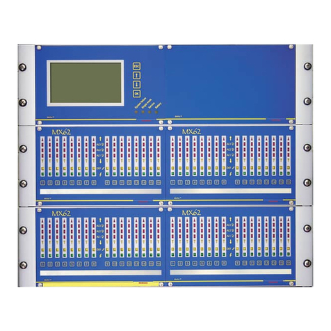
Example of a front side with LCD pannel
And keyboard for 64 detectors
A del(s) module is dedicated to8 channels.
A pannel with keyboard gets 2 DEL(s) modules
The channels are numbered from 1 to 16.
The pannel with keys are extensibled and are numbered from A to D.
Other manuals for MX62
1
Table of contents
Other Oldham Gas Detector manuals

Oldham
Oldham CPS Series User manual

Oldham
Oldham OLC 100 User manual

Oldham
Oldham OLC 10 User manual

Oldham
Oldham OLC 100 User manual

Oldham
Oldham OLC 100 User manual

Oldham
Oldham CTX 300 CO2 User manual

Oldham
Oldham OLCT 20 User manual

Oldham
Oldham OLC 10 User manual

Oldham
Oldham ctx 300 User manual

Oldham
Oldham SV 4B User manual