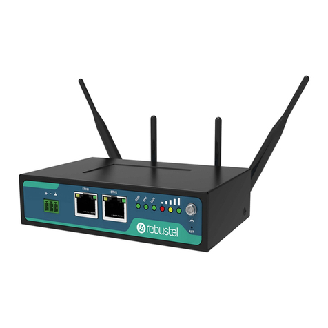
Vitriko XR5i v2 Instruction sheet

CONFIGURATION MANUAL
for v2 routers
,Anytime Anything Anywhere, , but always connected.
Industrial
LAN - 2G-3G-4
G Router
s
www.vitriko.com
VITRIKO
Mobile Data Experts
XR5i v2 - ER75i v2 - UR5i v2 - LR77
v2

VITRIKO
Mobile Data Experts
USED SYMBOLS
Used symbols
Danger – important notice, which may have an influence on the user’s safety or the function
of the device.
Attention – notice on possible problems, which can arise in specific cases.
Information, notice – information, which contains useful advice or special interest.
Firmware version
Actual version of firmware is 4.0.1 (August 25, 2014).
GPL licence
Source codes under GPL licence are available free of charge by sending an email to:
info@vitriko.com
Router version
Properties and settings of router associated with the GSM connection is not available in indus-
trial router XR5i v2.
PPPoE configuration item is only available on the industrial router XR5i v2, used to set the
PPPoE connection over Ethernet.
Manual issued in CZ, November 7, 2014
i

VITRIKO
Mobile Data Experts
CONTENTS
Contents
1 Configuration over web browser 1
1.1 Secured access to web configuration . . . . . . . . . . . . . . . . . . . . . . . . 2
1.2 General . . . . . . . . . . . . . . . . . . . . . . . . . . . . . . . . . . . . . . . . 2
1.2.1 Mobile Connection . . . . . . . . . . . . . . . . . . . . . . . . . . . . . . 2
1.2.2 Primary LAN ................................. 3
1.2.3 Peripheral Ports ............................... 3
1.2.4 System Information . . . . . . . . . . . . . . . . . . . . . . . . . . . . . . 3
1.3 Mobile WAN status .................................. 4
1.4 WiFi .......................................... 7
1.5 WiFi Scan....................................... 8
1.6 Network status .................................... 10
1.7 DHCP status ..................................... 12
1.8 IPsec status ...................................... 13
1.9 DynDNS status .................................... 13
1.10SystemLog...................................... 14
1.11 LAN configuration .................................. 15
1.12 VRRP configuration . . . . . . . . . . . . . . . . . . . . . . . . . . . . . . . . . 21
1.13 Mobile WAN configuration . . . . . . . . . . . . . . . . . . . . . . . . . . . . . . 23
1.13.1 Connection to mobile network . . . . . . . . . . . . . . . . . . . . . . . . 23
1.13.2 DNS address configuration . . . . . . . . . . . . . . . . . . . . . . . . . 24
1.13.3 Check connection to mobile network configuration . . . . . . . . . . . . 24
1.13.4 Data limit configuration . . . . . . . . . . . . . . . . . . . . . . . . . . . 25
1.13.5 Switch between SIM cards configuration . . . . . . . . . . . . . . . . . . 26
1.13.6 Dial-In access configuration . . . . . . . . . . . . . . . . . . . . . . . . . 28
1.13.7 PPPoE bridge mode configuration . . . . . . . . . . . . . . . . . . . . . 28
1.14 PPPoE Configuration . . . . . . . . . . . . . . . . . . . . . . . . . . . . . . . . . 31
1.15 WiFi configuration .................................. 32
1.16 WLAN configuration . . . . . . . . . . . . . . . . . . . . . . . . . . . . . . . . . 36
1.17 Backup Routes .................................... 38
1.18 Firewall configuration................................. 39
1.19 NAT configuration .................................. 43
1.20 OpenVPN tunnel configuration . . . . . . . . . . . . . . . . . . . . . . . . . . . 47
1.21 IPsec tunnel configuration . . . . . . . . . . . . . . . . . . . . . . . . . . . . . . 52
1.22 GRE tunnels configuration . . . . . . . . . . . . . . . . . . . . . . . . . . . . . . 57
1.23 L2TP tunnel configuration . . . . . . . . . . . . . . . . . . . . . . . . . . . . . . 60
1.24 PPTP tunnel configuration . . . . . . . . . . . . . . . . . . . . . . . . . . . . . . 62
1.25 DynDNS client configuration . . . . . . . . . . . . . . . . . . . . . . . . . . . . . 64
1.26 NTP client configuration . . . . . . . . . . . . . . . . . . . . . . . . . . . . . . . 65
1.27 SNMP configuration . . . . . . . . . . . . . . . . . . . . . . . . . . . . . . . . . 66
ii

VITRIKO
Mobile Data Experts
CONTENTS
1.28 SMTP configuration . . . . . . . . . . . . . . . . . . . . . . . . . . . . . . . . . 71
1.29 SMS configuration . . . . . . . . . . . . . . . . . . . . . . . . . . . . . . . . . . 72
1.29.1SendSMS .................................. 74
1.30 Expansion port configuration . . . . . . . . . . . . . . . . . . . . . . . . . . . . 80
1.31 USB port configuration . . . . . . . . . . . . . . . . . . . . . . . . . . . . . . . . 83
1.32 Startup script ..................................... 87
1.33 Up/Down script.................................... 88
1.34 Automatic update configuration . . . . . . . . . . . . . . . . . . . . . . . . . . . 89
1.35 User modules . . . . . . . . . . . . . . . . . . . . . . . . . . . . . . . . . . . . . 91
1.36 Change profile . . . . . . . . . . . . . . . . . . . . . . . . . . . . . . . . . . . . 92
1.37 Change password . . . . . . . . . . . . . . . . . . . . . . . . . . . . . . . . . . 93
1.38 Set real timeclock .................................. 93
1.39 Set SMS service center address . . . . . . . . . . . . . . . . . . . . . . . . . . 93
1.40 Unlock SIMcard ................................... 94
1.41 Send SMS . . . . . . . . . . . . . . . . . . . . . . . . . . . . . . . . . . . . . . 94
1.42 Backup configuration . . . . . . . . . . . . . . . . . . . . . . . . . . . . . . . . . 95
1.43 Restore configuration . . . . . . . . . . . . . . . . . . . . . . . . . . . . . . . . 95
1.44 Update firmware ................................... 95
1.45 Reboot ......................................... 96
2 Configuration setting over Telnet 97
iii

VITRIKO
Mobile Data Experts
LIST OF FIGURES
List of Figures
1Web configuration .................................. 1
2 Mobile WAN status .................................. 6
3WiFi Status ...................................... 7
4WiFi Scan....................................... 9
5 Network status .................................... 11
6 DHCP status ..................................... 12
7 IPsec status ...................................... 13
8 DynDNS status .................................... 13
9 SystemLog...................................... 15
10 Example program syslogd start with the parameter -r . . . . . . . . . . . . . . . 15
11 Topology of example LAN configuration 1 . . . . . . . . . . . . . . . . . . . . . 17
12 Example LAN configuration 1 . . . . . . . . . . . . . . . . . . . . . . . . . . . . 18
13 Topology of example LAN configuration 2 . . . . . . . . . . . . . . . . . . . . . 19
14 Example LAN configuration 2 . . . . . . . . . . . . . . . . . . . . . . . . . . . . 19
15 Topology of example LAN configuration 3 . . . . . . . . . . . . . . . . . . . . . 20
16 Example LAN configuration 3 . . . . . . . . . . . . . . . . . . . . . . . . . . . . 20
17 Topology of example VRRP configuration . . . . . . . . . . . . . . . . . . . . . 22
18 Example VRRP configuration — main router .................... 22
19 Example VRRP configuration -– backup router .................. 22
20 Mobile WAN configuration . . . . . . . . . . . . . . . . . . . . . . . . . . . . . . 29
21 Example of Mobile WAN configuration 1 . . . . . . . . . . . . . . . . . . . . . . 30
22 Example of Mobile WAN configuration 2 . . . . . . . . . . . . . . . . . . . . . . 30
23 Example of Mobile WAN configuration 3 . . . . . . . . . . . . . . . . . . . . . . 30
24 PPPoE configuration . . . . . . . . . . . . . . . . . . . . . . . . . . . . . . . . . 31
25 WiFi konfigurace ................................... 35
26 WLAN configuration . . . . . . . . . . . . . . . . . . . . . . . . . . . . . . . . . 37
27 Backup Routes .................................... 39
28 Firewall configuration................................. 41
29 Topology of example firewall configuration . . . . . . . . . . . . . . . . . . . . . 42
30 Example firewall configuration . . . . . . . . . . . . . . . . . . . . . . . . . . . . 42
31 Topology of example NAT configuration 1 . . . . . . . . . . . . . . . . . . . . . 44
32 Example NAT configuration 1 . . . . . . . . . . . . . . . . . . . . . . . . . . . . 45
33 Topology of example NAT configuration 2 . . . . . . . . . . . . . . . . . . . . . 46
34 Example NAT configuration 2 . . . . . . . . . . . . . . . . . . . . . . . . . . . . 46
35 OpenVPN tunnels configuration . . . . . . . . . . . . . . . . . . . . . . . . . . . 47
36 OpenVPN tunnel configuration . . . . . . . . . . . . . . . . . . . . . . . . . . . 50
37 Topology of example OpenVPN configuration . . . . . . . . . . . . . . . . . . . 51
38 IPsec tunnels configuration . . . . . . . . . . . . . . . . . . . . . . . . . . . . . 52
39 IPsec tunnels configuration . . . . . . . . . . . . . . . . . . . . . . . . . . . . . 56
40 Topology of example IPsec configuration . . . . . . . . . . . . . . . . . . . . . . 57
iv

VITRIKO
Mobile Data Experts
LIST OF FIGURES
41 GRE tunnels configuration . . . . . . . . . . . . . . . . . . . . . . . . . . . . . . 58
42 GRE tunnel configuration . . . . . . . . . . . . . . . . . . . . . . . . . . . . . . 59
43 Topology of GRE tunnel configuration . . . . . . . . . . . . . . . . . . . . . . . 59
44 L2TP tunnel configuration . . . . . . . . . . . . . . . . . . . . . . . . . . . . . . 60
45 Topology of example L2TP tunnel configuration . . . . . . . . . . . . . . . . . . 61
46 PPTP tunnel configuration . . . . . . . . . . . . . . . . . . . . . . . . . . . . . . 62
47 Topology of example PPTP tunnel configuration . . . . . . . . . . . . . . . . . . 63
48 Example of DynDNS configuration . . . . . . . . . . . . . . . . . . . . . . . . . 64
49 Example of NTP configuration . . . . . . . . . . . . . . . . . . . . . . . . . . . . 65
50 Example of SNMP configuration . . . . . . . . . . . . . . . . . . . . . . . . . . 69
51 Example of the MIB browser . . . . . . . . . . . . . . . . . . . . . . . . . . . . . 70
52 SMTP configuration . . . . . . . . . . . . . . . . . . . . . . . . . . . . . . . . . 71
53 Example of SMS configuration 1 . . . . . . . . . . . . . . . . . . . . . . . . . . 76
54 Example of SMS configuration 2 . . . . . . . . . . . . . . . . . . . . . . . . . . 77
55 Example of SMS configuration 3 . . . . . . . . . . . . . . . . . . . . . . . . . . 78
56 Example of SMS configuration 4 . . . . . . . . . . . . . . . . . . . . . . . . . . 79
57 Expansion port configuration . . . . . . . . . . . . . . . . . . . . . . . . . . . . 81
58 Example of expansion port configuration 1 . . . . . . . . . . . . . . . . . . . . . 82
59 Example of expansion port configuration 2 . . . . . . . . . . . . . . . . . . . . . 82
60 USB configuration . . . . . . . . . . . . . . . . . . . . . . . . . . . . . . . . . . 85
61 Example of USB port configuration 1 . . . . . . . . . . . . . . . . . . . . . . . . 85
62 Example of USB port configuration 2 . . . . . . . . . . . . . . . . . . . . . . . . 86
63 Startup script ..................................... 87
64 Example of Startup script .............................. 87
65 Up/Down script.................................... 88
66 Example of Up/Down script ............................. 88
67 Example of automatic update 1 . . . . . . . . . . . . . . . . . . . . . . . . . . . 90
68 Example of automatic update 2 . . . . . . . . . . . . . . . . . . . . . . . . . . . 90
69 Usermodules..................................... 91
70 Added usermodule.................................. 91
71 Changeprofile .................................... 92
72 Changepassword .................................. 93
73 Set real timeclock .................................. 93
74 Set SMS service center address . . . . . . . . . . . . . . . . . . . . . . . . . . 94
75 Unlock SIMcard ................................... 94
76 Send SMS . . . . . . . . . . . . . . . . . . . . . . . . . . . . . . . . . . . . . . 94
77 Restore configuration ................................ 95
78 Update firmware ................................... 95
79 Reboot ......................................... 96
v

VITRIKO
Mobile Data Experts
LIST OF TABLES
List of Tables
1 Mobileconnection .................................. 3
2Peripheral Ports ................................... 3
3 System Information . . . . . . . . . . . . . . . . . . . . . . . . . . . . . . . . . . 4
4 Mobile Network Information . . . . . . . . . . . . . . . . . . . . . . . . . . . . . 5
5 Description of period . . . . . . . . . . . . . . . . . . . . . . . . . . . . . . . . . 5
6 Mobile Network Statistics .............................. 5
7Traffic statistics .................................... 6
8State information about access point . . . . . . . . . . . . . . . . . . . . . . . . 7
9State information about connected clients . . . . . . . . . . . . . . . . . . . . . 7
10 Information about neighbouring WiFi networks . . . . . . . . . . . . . . . . . . 8
11 Description of interface in network status ...................... 10
12 Description of information in network status .................... 11
13 DHCP status description . . . . . . . . . . . . . . . . . . . . . . . . . . . . . . . 12
14 Configuration of network interface . . . . . . . . . . . . . . . . . . . . . . . . . 16
15 Configuration of dynamic DHCP server . . . . . . . . . . . . . . . . . . . . . . 17
16 Configuration of static DHCP server . . . . . . . . . . . . . . . . . . . . . . . . 17
17 VRRP configuration . . . . . . . . . . . . . . . . . . . . . . . . . . . . . . . . . 21
18 Check connection . . . . . . . . . . . . . . . . . . . . . . . . . . . . . . . . . . 21
19 Mobile WAN connection configuration . . . . . . . . . . . . . . . . . . . . . . . 23
20 Check connection to mobile network configuration . . . . . . . . . . . . . . . . 25
21 Data limit configuration . . . . . . . . . . . . . . . . . . . . . . . . . . . . . . . . 25
22 Default and backup SIM configuration . . . . . . . . . . . . . . . . . . . . . . . 26
23 Switch between SIM card configurations . . . . . . . . . . . . . . . . . . . . . . 27
24 Switch between SIM card configurations . . . . . . . . . . . . . . . . . . . . . . 27
25 Dial-In access configuration . . . . . . . . . . . . . . . . . . . . . . . . . . . . . 28
26 PPPoE configuration . . . . . . . . . . . . . . . . . . . . . . . . . . . . . . . . . 31
27 WiFi configuration .................................. 35
28 WLAN configuration . . . . . . . . . . . . . . . . . . . . . . . . . . . . . . . . . 36
29 Configuration of DHCP server . . . . . . . . . . . . . . . . . . . . . . . . . . . . 37
30 Backup Routes .................................... 38
31 Filtering of incoming packets . . . . . . . . . . . . . . . . . . . . . . . . . . . . 40
32 Forwarding filtering . . . . . . . . . . . . . . . . . . . . . . . . . . . . . . . . . . 41
33 NAT configuration . . . . . . . . . . . . . . . . . . . . . . . . . . . . . . . . . . 43
34 Configuration of send all incoming packets . . . . . . . . . . . . . . . . . . . . . 43
35 Remote access configuration . . . . . . . . . . . . . . . . . . . . . . . . . . . . 44
36 Overview OpenVPN tunnels . . . . . . . . . . . . . . . . . . . . . . . . . . . . . 47
37 OpenVPN tunnels configuration . . . . . . . . . . . . . . . . . . . . . . . . . . . 49
38 Example OpenVPN configuration . . . . . . . . . . . . . . . . . . . . . . . . . . 51
39 Overview IPsec tunnels . . . . . . . . . . . . . . . . . . . . . . . . . . . . . . . 52
40 IPsec tunnel configuration . . . . . . . . . . . . . . . . . . . . . . . . . . . . . . 54
vi

VITRIKO
Mobile Data Experts
LIST OF TABLES
41 Example IPsec configuration . . . . . . . . . . . . . . . . . . . . . . . . . . . . 57
42 Overview GRE tunnels . . . . . . . . . . . . . . . . . . . . . . . . . . . . . . . . 58
43 GRE tunnel configuration . . . . . . . . . . . . . . . . . . . . . . . . . . . . . . 58
44 Example GRE tunnel configuration . . . . . . . . . . . . . . . . . . . . . . . . . 59
45 L2TP tunnel configuration . . . . . . . . . . . . . . . . . . . . . . . . . . . . . . 60
46 Example L2TP tunel configuration . . . . . . . . . . . . . . . . . . . . . . . . . 61
47 PPTP tunnel configuration . . . . . . . . . . . . . . . . . . . . . . . . . . . . . . 62
48 Example PPTP tunel configuration . . . . . . . . . . . . . . . . . . . . . . . . . 63
49 DynDNS configuration . . . . . . . . . . . . . . . . . . . . . . . . . . . . . . . . 64
50 NTP configuration . . . . . . . . . . . . . . . . . . . . . . . . . . . . . . . . . . 65
51 SNMP agent configuration . . . . . . . . . . . . . . . . . . . . . . . . . . . . . . 66
52 SNMPv3 configuration . . . . . . . . . . . . . . . . . . . . . . . . . . . . . . . . 66
53 SNMP configuration (MBUS extension) ...................... 67
54 SNMP configuration (R-SeeNet) . . . . . . . . . . . . . . . . . . . . . . . . . . 67
55 Object identifier for binary input and output . . . . . . . . . . . . . . . . . . . . 67
56 Object identifier for CNTport ............................ 68
57 Object identifier for M-BUSport........................... 68
58 SMTP client configuration . . . . . . . . . . . . . . . . . . . . . . . . . . . . . . 71
59 Send SMS configuration . . . . . . . . . . . . . . . . . . . . . . . . . . . . . . . 73
60 Control via SMS configuration . . . . . . . . . . . . . . . . . . . . . . . . . . . . 73
61 Control SMS . . . . . . . . . . . . . . . . . . . . . . . . . . . . . . . . . . . . . 74
62 Send SMS on serial PORT1 configuration . . . . . . . . . . . . . . . . . . . . . 74
63 Send SMS on serial PORT2 configuration . . . . . . . . . . . . . . . . . . . . . 74
64 Send SMS on ethernet PORT1 configuration . . . . . . . . . . . . . . . . . . . 74
65 List of AT commands . . . . . . . . . . . . . . . . . . . . . . . . . . . . . . . . . 75
66 Expansion PORT configuration 1 . . . . . . . . . . . . . . . . . . . . . . . . . . 80
67 Expansion PORT configuration 2 . . . . . . . . . . . . . . . . . . . . . . . . . . 80
68 CD signal description . . . . . . . . . . . . . . . . . . . . . . . . . . . . . . . . . 81
69 DTR signal description . . . . . . . . . . . . . . . . . . . . . . . . . . . . . . . . 81
70 USB port configuration 1 . . . . . . . . . . . . . . . . . . . . . . . . . . . . . . . 83
71 USB PORT configuration 2 . . . . . . . . . . . . . . . . . . . . . . . . . . . . . 84
72 CD signal description . . . . . . . . . . . . . . . . . . . . . . . . . . . . . . . . . 84
73 DTR signal description . . . . . . . . . . . . . . . . . . . . . . . . . . . . . . . . 84
74 Automatic update configuration . . . . . . . . . . . . . . . . . . . . . . . . . . . 89
75 User modules . . . . . . . . . . . . . . . . . . . . . . . . . . . . . . . . . . . . . 92
76 Telnet commands . . . . . . . . . . . . . . . . . . . . . . . . . . . . . . . . . . . 98
vii

VITRIKO
Mobile Data Experts
1. CONFIGURATION OVER WEB BROWSER
1. Configuration over web browser
Attention! If the SIM card is not inserted in the router, then wireless transmissions will not
work. The inserted SIM card must have activated GPRS. Insert the SIM card when the router
is switched-off.
For monitoring, configuring and managing the router use web interface, which can be
invoked by entering the IP address of the router into your browser. The default IP address of
the router is 192.168.1.1. Configuration may be performed only by the user "root" with initial
password "root".
The left part of the web interface contains the menu with pages for monitoring (Status),
Configuration,Customization and Administration of the router.
Name and Location items displays the name and location of the router filled in the SNMP
configuration (see SNMP Configuration).
For increased safety of the network managed by the router must be changed the default
router password. If the router’s default password is set, the Change password item is high-
lighted in red.
Figure 1: Web configuration
1

VITRIKO
Mobile Data Experts
1. CONFIGURATION OVER WEB BROWSER
After green LED starts to blink it is possible to restore initial settings of the router by press-
ing button RST on front panel. If press button RST, configuration is restored to default and it
is reboot (green LED will be on).
1.1 Secured access to web configuration
To the web configuration can be accessed via a secure HTTPS protocol. In the event
of a default router IP address is a secure router configuration accessed by entering address
https://192.168.1.1 in the web browser. The first approach is the need to install a security cer-
tificate. If your browser reports a disagreement in the domain, this message can be prevented
use the following procedure.
Since the domain name in the certificate is given the MAC address of the router (such
separators are used dashes instead of colons), it is necessary to access the router under this
domain name. For access to the router via a domain name, it is adding a DNS record in the
DNS table, the operating system.
•Editing /etc/hosts (Linux/Unix)
•Editing C:\WINDOWS\system32\drivers\etc\hosts (Windows XP)
•Configuring your own DNS server
In addition to configuring the router with MAC address 00:11:22:33:44:55 is accessed to
secure configuration by typing address https://00-11-22-33-44-55 in the web browser. The first
approach is the need to install a security certificate.
When using self signing certificate must upload your files and http_cert http_key directory
/etc/certs in the router.
1.2 General
A summary of basic information about the router and its activities can be invoked by se-
lecting the General item. This page is also displayed when you login to the web interface.
Information is divided into a several of separate blocks according to the type of router activ-
ity or the properties area – Mobile Connection,Primary LAN,Peripherals Ports and System
Information. If your router is equipped with WIFI expansion port, there is also WIFI section.
1.2.1 Mobile Connection
Item Description
SIM Card Identification of the SIM card (Primary or Secondary)
Interface Defines the interface
Flags Displays network interface flags
IP Address IP address of the interface
Continued on next page
2

VITRIKO
Mobile Data Experts
1. CONFIGURATION OVER WEB BROWSER
Continued from previous page
Item Description
MTU Maximum packet size that the equipment is able to transmit
Rx Data Total number of received bytes
Rx Packets Received packets
Rx Errors Erroneous received packets
Rx Dropped Dropped received packets
Rx Overruns Lost received packets because of overload
Tx Data Total number of sent bytes
Tx Packets Sent packets
Tx Errors Erroneous sent packets
Tx Dropped Dropped sent packets
Tx Overruns Lost sent packets because of overload
Uptime Indicates how long the connection to mob. network is established
Table 1: Mobile connection
1.2.2 Primary LAN
Items displayed in this part have the same meaning as items in the previous part. Moreover,
there is information about the MAC address of the router (MAC Address item).
1.2.3 Peripheral Ports
Item Description
Expansion Port 1 Expansion port fitted to the position 1 (None indicates that this
position is equipped with no port)
Expansion Port 2 Expansion port fitted to the position 2 (None indicates that this
position is equipped with no port)
Binary Input State of binary input
Binary Output State of binary output
Table 2: Peripheral Ports
1.2.4 System Information
Item Description
Firmware Version Information about the firmware version
Serial Number Serial number of the router (in case of N/A is not available)
Continued on next page
3

VITRIKO
Mobile Data Experts
1. CONFIGURATION OVER WEB BROWSER
Continued from previous page
Item Description
Profile Current profile – standard or alternative profiles (profiles are used
for example to switch between different modes of operation)
Supply Voltage Supply voltage of the router
Temperature Temperature in the router
Time Current date and time
Uptime Indicates how long the router is used
Table 3: System Information
1.3 Mobile WAN status
This item is not available for industrial router XR5i v2.
The Mobile WAN menu item contains current information about connections to the mobile
network. The first part of this page (Mobile Network Information) displays basic information
about mobile network in which the router is operated. There is also information about the
module, which is mounted in the router.
Item Description
Registration State of the network registration
Operator Specifies the operator in whose network the router is operated
Technology Transmission technology
PLMN Code of operator
Cell Cell to which the router is connected
LAC Location Area Code – unique number assigned to each location area
Channel Channel on which the router communicates
Signal Strength Signal strength of the selected cell
Signal Quality Signal quality of the selected cell:
•EC/IO for UMTS and CDMA (it’s the ratio of the signal received
from the pilot channel –EC–to the overall level of the spectral
density, ie the sum of the signals of other cells – IO)
•RSRQ for LTE technology (Defined as the ratio N×RSRP
RSSI
)
•For EDGE technology (router ER75i v2) value is not available
Neighbours Signal strength of neighboring hearing cells
Manufacturer Module manufacturer
Continued on next page
4

VITRIKO
Mobile Data Experts
1. CONFIGURATION OVER WEB BROWSER
Continued from previous page
Item Description
Model Type of module
Revision Revision of module
IMEI IMEI (International Mobile Equipment Identity) number of module
ESN ESN (Electronic Serial Number) number of module (for CDMA routers)
MEID MEID number of module
Table 4: Mobile Network Information
Highlighted in red adjacent cells have a close signal quality, which means that there is
imminence of frequent switching between the current and the highlighted cell.
The next section of this window displays information about the quality of the connection in
each period.
Period Description
Today Today from 0:00 to 23:59
Yesterday Yesterday from 0:00 to 23:59
This week This week from Monday 0:00 to Sunday 23:59
Last week Last week from Monday 0:00 to Sunday 23:59
This period This accounting period
Last period Last accounting period
Table 5: Description of period
Item Description
Signal Min Minimal signal strength
Signal Avg Average signal strength
Signal Max Maximal signal strength
Cells Number of switch between cells
Availability Availability of the router via the mobile network (expressed as a percent-
age)
Table 6: Mobile Network Statistics
Tips for Mobile Network Statistics table:
•Availability of connection to mobile network is information expressed as a percentage
that is calculated by the ratio of time when connection to mobile network is established
to the time when the router is turned on.
5

VITRIKO
Mobile Data Experts
1. CONFIGURATION OVER WEB BROWSER
•After you place your cursor on the maximum or minimum signal strength, the last time
when the router reached this signal strength is displayed.
In the middle part of this page is displayed information about transferred data and number
of connections for both SIM card (for each period).
Item Description
RX data Total volume of received data
TX data Total volume of sent data
Connections Number of connection to mobile network establishment
Table 7: Traf fic statistics
The last part (Mobile Network Connection Log) informs about the mobile network connec-
tion and problems in establishment.
Figure 2: Mobile WAN status
6

VITRIKO
Mobile Data Experts
1. CONFIGURATION OVER WEB BROWSER
1.4 WiFi
This item is available only if the router is equipped with a WiFi module.
After selecting the WiFi item in the main menu of the web interface, information about WiFi
access point (AP) and associated stations is displayed.
Item Description
hostapd state dump Time to which statistical data relates
num_sta Number of connected stations
num_sta_non_erp Number of connected stations using 802.11b in 802.11g
BSS connection
num_sta_no_short_slot_time Number of stations not supporting the Short Slot Time
num_sta_no_short_preamble Number of stations not supporting the Short Preamble
Table 8: State information about access point
For each connected client are displayed more detailed information. Most of them has an
internal character, so let us mention only the following:
Item Description
STA MAC address of connected device (station)
AID Identifier of connected device (1 – 2007). If 0 is displayed, the station is
not currently connected.
Table 9: State information about connected clients
Figure 3: WiFi Status
7

VITRIKO
Mobile Data Experts
1. CONFIGURATION OVER WEB BROWSER
1.5 WiFi Scan
This item is available only if the router is equipped with a WiFi module.
After selecting the WiFi Scan item in the menu of the web interface, scanning of neigh-
bouring WiFi networks and subsequent printing of results are invoked. Scanning can be per-
formed only if the access point (WiFi AP) is off.
item Description
BSS MAC address of access point (AP)
TSF ATiming Synchronization Function (TSF) keeps the timers for
all stations in the same Basic Service Set (BSS) synchronized.
All stations shall maintain a local TSF timer.
freq Frequency band of WiFi network [kHz]
beacon interval Period of time synchronization
capability List of access point (AP) properties
signal Signal level of access point (AP)
last seen Last response time of access point (AP)
SSID Identifier of access point (AP)
Supported rates Supported rates of access point (AP)
DS Parameter set The channel on which access point (AP) broadcasts
ERP Extended Rate PHY – information element providing backward
compatibility
Extended supported
rates
Supported rates of access point (AP) that are beyond the scope
of eight rates mentioned in Supported rates item
RSN Robust Secure Network – The protocol for establishing a se-
cure communication through wireless network 802.11
Table 10: Information about neighbouring WiFi networks
8

VITRIKO
Mobile Data Experts
1. CONFIGURATION OVER WEB BROWSER
Figure 4: WiFi Scan
9

VITRIKO
Mobile Data Experts
1. CONFIGURATION OVER WEB BROWSER
1.6 Network status
To view system information about the router operation, select the Network item in the main
menu. The upper part of the window displays detailed information about active interfaces:
Interface Description
eth0, eth1 Network interfaces (ethernet connection)
ppp0 Interface (active connection to GPRS/EDGE)
tun0 OpenVPN tunnel interface
ipsec0 IPSec tunnel interface
gre1 GRE tunnel interface
usb0 USB interface
Table 11: Description of interface in network status
By each of the interfaces is then shown the following information:
Item Description
HWaddr Hardware (unique) address of networks interface
inet IP address of interface
P-t-P IP address second ends connection
Bcast Broadcast address
Mask Mask of network
MTU Maximum packet size that the equipment is able to transmit
Metric Number of routers, over which packet must go trought
RX •packets –received packets
•errors – number of errors
•dropped – dropped packets
•overruns – incoming packets lost because of overload
•frame – wrong incoming packets because of incorrect packet size
TX •packets – transmit packets
•errors – number of errors
•dropped – dropped packets
•overruns – outgoing packets lost because of overload
•carrier – wrong outgoing packets with errors resulting from the
physical layer
Continued on next page
10

VITRIKO
Mobile Data Experts
1. CONFIGURATION OVER WEB BROWSER
Continued from previous page
Item Description
collisions Number of collisions on physical layer
txqueuelen Length of front network device
RX bytes Total number of received bytes
TX bytes Total number of transmitted bytes
Table 12: Description of information in network status
It is possible to read status of connection to mobile network from the network information.
If the connection to mobile network is active, then it is in the system information shown as a
ppp0 interface.
For industrial router XR5i v2, interface ppp0 indicates PPPoE connection.
Figure 5: Network status
11

VITRIKO
Mobile Data Experts
1. CONFIGURATION OVER WEB BROWSER
1.7 DHCP status
Information on the activities of the DHCP server can be accessed by selecting the DHCP
status item.
DHCP status informs about activities DHCP server. The DHCP server provides automatic
configuration of devices connected to the network managed router. DHCP server assigns to
each device’s IP address, netmask, default gateway (IP address of router) and DNS server (IP
address of router).
For each configuration, the DHCP status window displays the following information.
Item Description
lease Assigned IP address
starts Time of assignation of IP address
ends Time of termination IP address validity
hardware ethernet Hardware MAC (unique) address
uid Unique ID
client-hostname Computer name
Table 13: DHCP status description
In the extreme case, the DHCP status can display two records for one IP address. That
could have been caused by resetting of network cards.
Figure 6: DHCP status
Note: Starting with firmware 4.0.0, records in the DHCP status window are divided into two
separate parts – Active DHCP Leases (Primary LAN) and Active DHCP Leases (WLAN).
12
This manual suits for next models
3
Table of contents
