Ursalink UR35 User manual
1
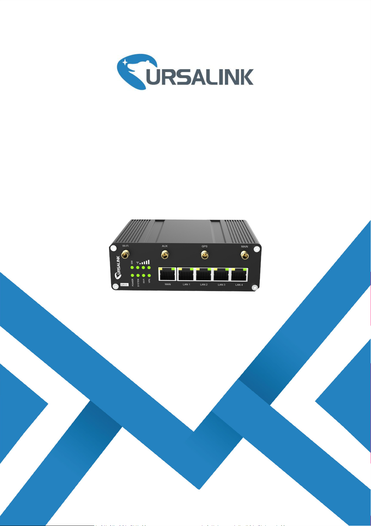
UR35
Industrial Cellular Router
Quick Start Guide
Ursalink Technology Co., Ltd.
www.ursalink.com
1
Welcome
Thank you for choosing Ursalink UR35 industrial cellular router.
This guide describes how to install the UR35 and how to log in the Web GUI to configure the device. Once
you complete the installation, refer to the Ursalink UR35 User Guide for instructions on how to perform
configurations on the device.
Related Documents
This Start Guide only explains the installation of Ursalink UR35 router. For more functionality and advanced
settings, please refer to the relevant documents as below.
Document
Description
Ursalink UR35 Datasheet
Datasheet for the Ursalink UR35 industrial cellular router.
Ursalink UR32&UR35 User Guide
Users could refer to the guide for instruction on how to log in the
web GUI, and how to configure all the settings.
The related documents are available on Ursalink website: http://www.ursalink.com.
Declaration of Conformity
UR35 are in conformity with the essential requirements and other relevant provisions of the CE, FCC, and
RoHS.
For assistance, please contact
Ursalink technical support:
Email: support@ursalink.com
Tel: 86-592-5023060
Fax: 86-592-5023065
Ursalink UR35 Quick Start Guide
www.ursalink.com
2
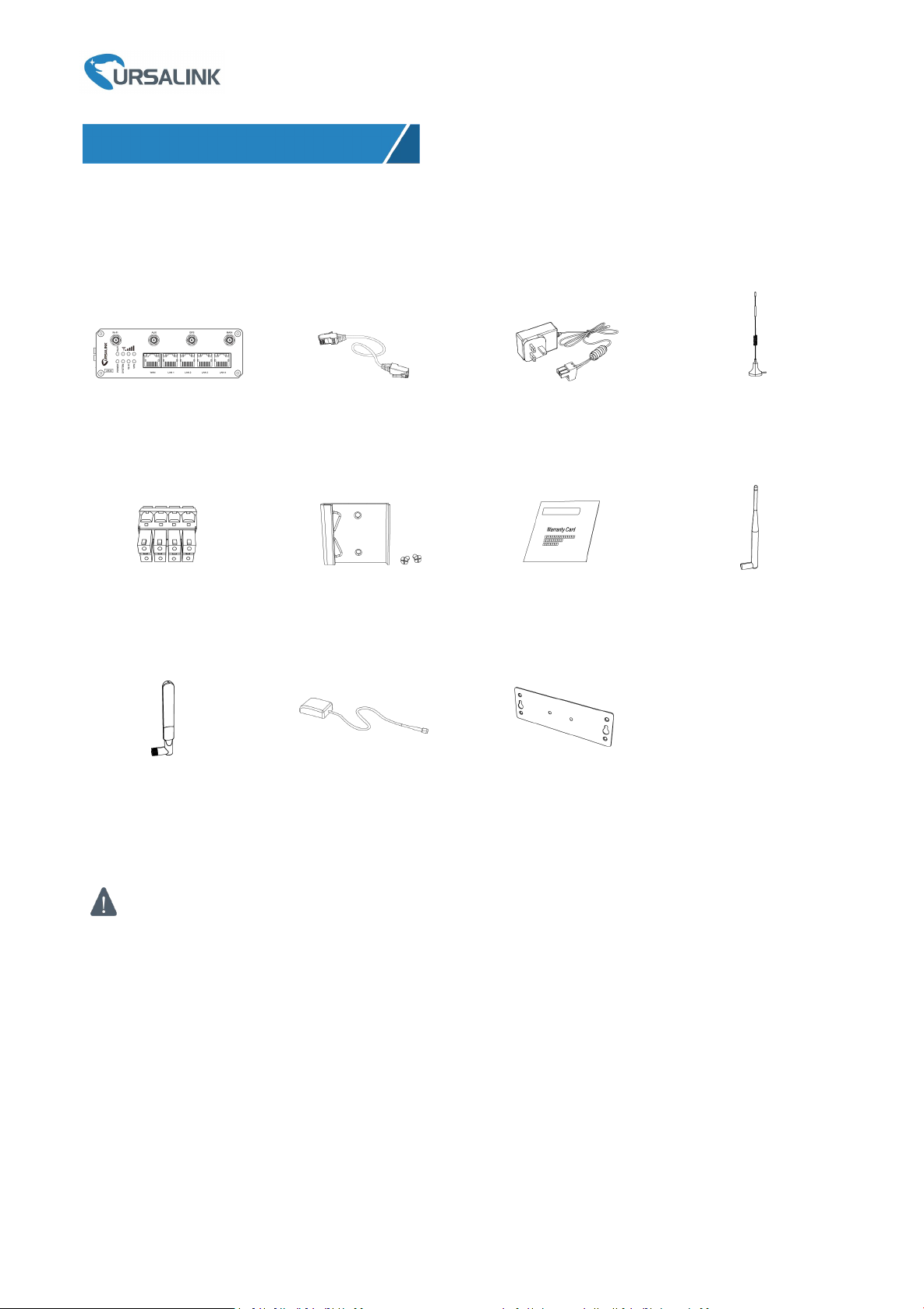
Before you begin to install the UR35 router, please check the package contents to verify that you have
received the items below.
1.1 Package Contents
1 × UR35 or
1 × Ethernet Cable
1 × Power Adapter
2 × Magnetic Mount
Cellular Antennas
1 × Stubby Wi-Fi
Antenna (Optional)
1 × GPS Antenna
(Optional)
1 × Wall Mounting
Bracket (Optional)
If any of the above items is missing or damaged, please contact your Ursalink sales
representative.
1 × 8-Pin Pluggable
Terminal
1 × DIN Rail Kit
1 × Warranty Card
2 × Stubby Cellular
Antennas (Optional)
1. Packing List
Ursalink UR35 Quick Start Guide
www.ursalink.com
3
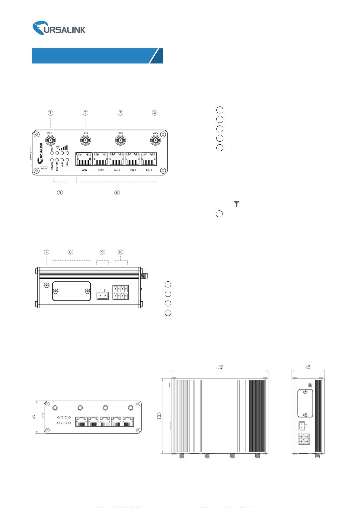
2.1 Overview
A. Front Panel
B. Left Side Panel
7Grounding Stud
8SIM and Reset Button Holder
9Power Connector
10 Serial Port & I/O
2.2 Dimensions (mm)
2. Hardware Introduction
1Wi-Fi Antenna Connector
2AUX Antenna Cellular Connector
3GPS Antenna Connector
4MAIN Cellular Antenna Connector
5LED Indicator Area
POWER: Power Indicator
SYSTEM: Status Indicator
Wi-Fi: Wi-Fi Indicator
VPN: VPN Indicator
SIM : SIM Status Indicator
: Signal Strength Indicator
6Ethernet Port & Indicator
Ursalink UR35 Quick Start Guide
www.ursalink.com
4
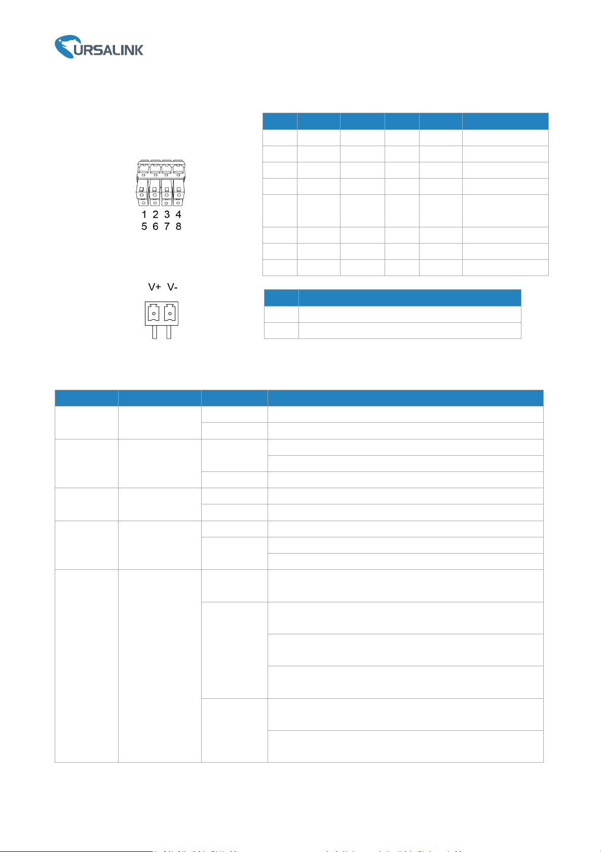
2.3 Pinouts
2.4 LED Indicators
LED
Indication
Status
Description
POWER
Power Status
Off
The power is switched off
On
The power is switched on
SYSTEM
System Status
Green Light
Static: Start-up
Blinking slowly: the system is running properly
Red Light
The system goes wrong
VPN
VPN Status
Off
VPN is disconnected
Green Light
VPN is connected
Wi-Fi
Wi-Fi Status
Off
Wi-Fi is disabled
Green Light
Static: Wi-Fi is enabled
Blinking slowly: sending or receiving data via Wi-Fi
SIM
SIM Card Status
Off
SIM1 or SIM2 is registering or fails to register (or there are
no SIM cards inserted)
Green Light
Blinking slowly: SIM1 (as primary SIM) has been registered
and is ready for dial-up
Blinking rapidly: SIM1(as primary SIM) has been registered
and is dialing up now
Static: SIM1 (as primary SIM) has been registered and
dialed up successfully
Orange
Light
Blinking slowly: SIM2 (as primary SIM) has been registered
and is ready for dial-up
Blinking rapidly: SIM2 (as primary SIM) 9has been
registered and is dialing up now
PIN
RS232
RS485
DI
DO
Description
1
---
---
IN
---
Digital Input
2
GND
---
GND
---
Ground
3
---
B
---
---
Data -
4
TXD
---
---
---
Transmit Data
5
---
---
---
COM
Common
Ground
6
---
---
---
OUT
Digital Output
7
---
A
---
---
Data +
8
RXD
---
---
---
Receive Data
PIN
Description
9
Positive
10
Negative
Ursalink UR35 Quick Start Guide
www.ursalink.com
5
Static: SIM2 (as primary SIM) has been registered and
dialed up successfully
Signal
Strength
Signal 1/2/3
Off
No signal
Green Light
Static/Off/Off: weak signals with 1-10 ASU (please check if
the antenna is installed correctly, or move the antenna to
a suitable location to get better signal)
Static/Static/Off: normal signals with 11-20 ASU (average
signal strength)
Static/Static/Static: strong signals with 21-31 ASU (signal is
good)
2.5 Reset Button
Function
Description
SYSTEM LED
Action
Reboot
Blinking
Press and hold the reset button for about 5-15 seconds.
Static Green
Release the button and wait for system to reboot.
Reset
Blinking
Press and hold the reset button for more than 15 seconds.
Static Green →
Rapidly Blinking
Release the button and wait.
Off → Blinking
The router is now reset to factory defaults.
2.6 Ethernet Port Indicator
Indicator
Status
Description
Link Indicator (Orange)
On
Connected
Blinking
Transmitting data
Off
Disconnected
Ursalink UR35 Quick Start Guide
www.ursalink.com
6
Environmental Requirements
- Power Input: 9-48 VDC
- Power Consumption: Typical 3.9 W, Max 4.6 W
- Operating Temperature: -40°C to 70°C (-40°F -158°F)
- Relative Humidity: 0% to 95% (non-condensing) at 25°C/77°F
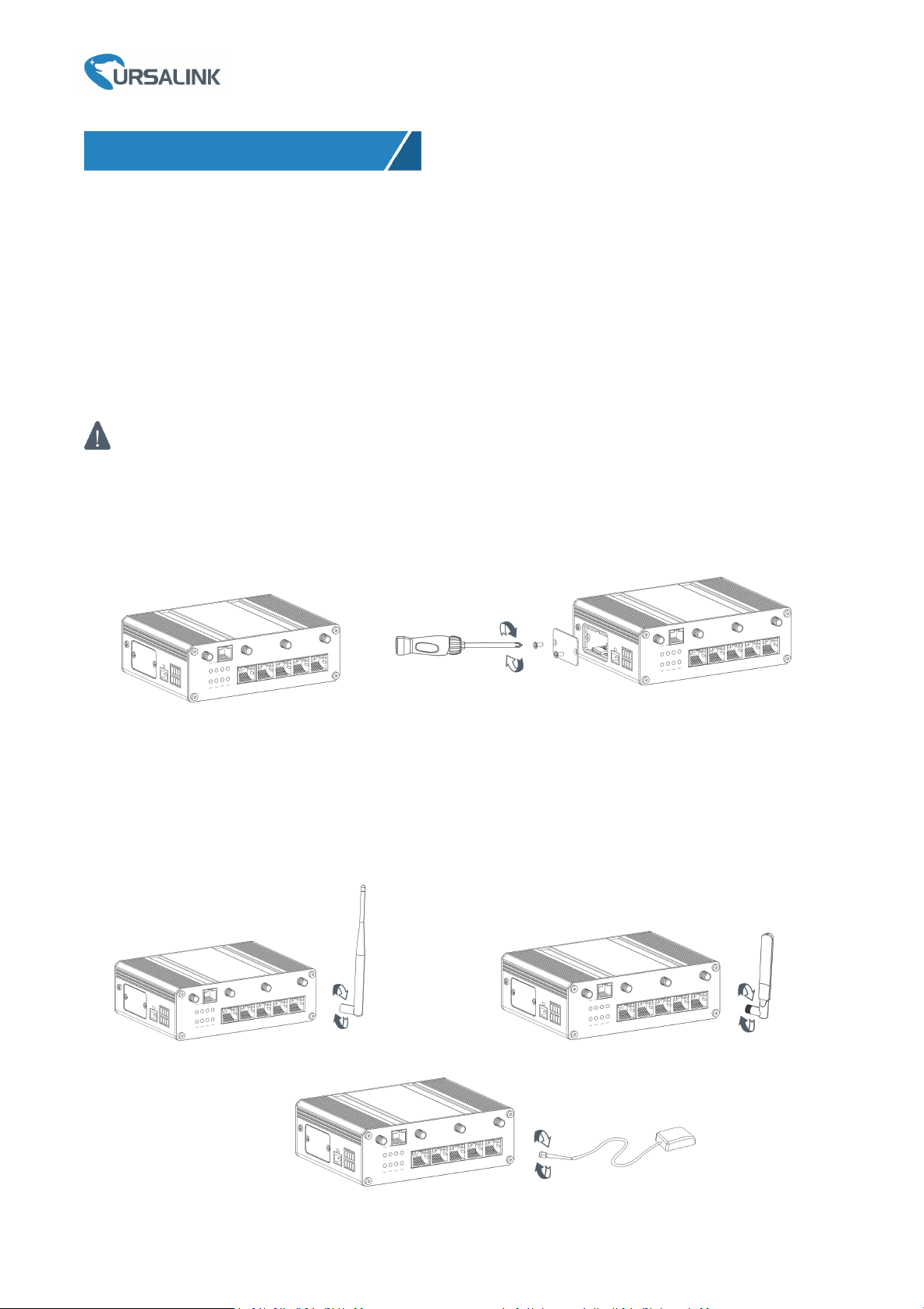
3.1 SIM Card/Micro SD Card Installation
UR35 do not support hot-plug. Please cut off the power before insert or take off cards.
A. Unscrew the cover of the SIM card/Micro SD B. Put SIM card/Micro SD card into the slot
then insert the card then take it off. and screw it up.
3.2 Antenna Installation
Rotate the antenna into the antenna connector accordingly.
The external antenna should be installed vertically always on a site with a good signal.
3. Hardware Installation

Ursalink UR35 Quick Start Guide
www.ursalink.com
7
3.3 Connect the Router to a Computer
Please connect PC to any port among LAN1-LAN4 of UR35 router directly.
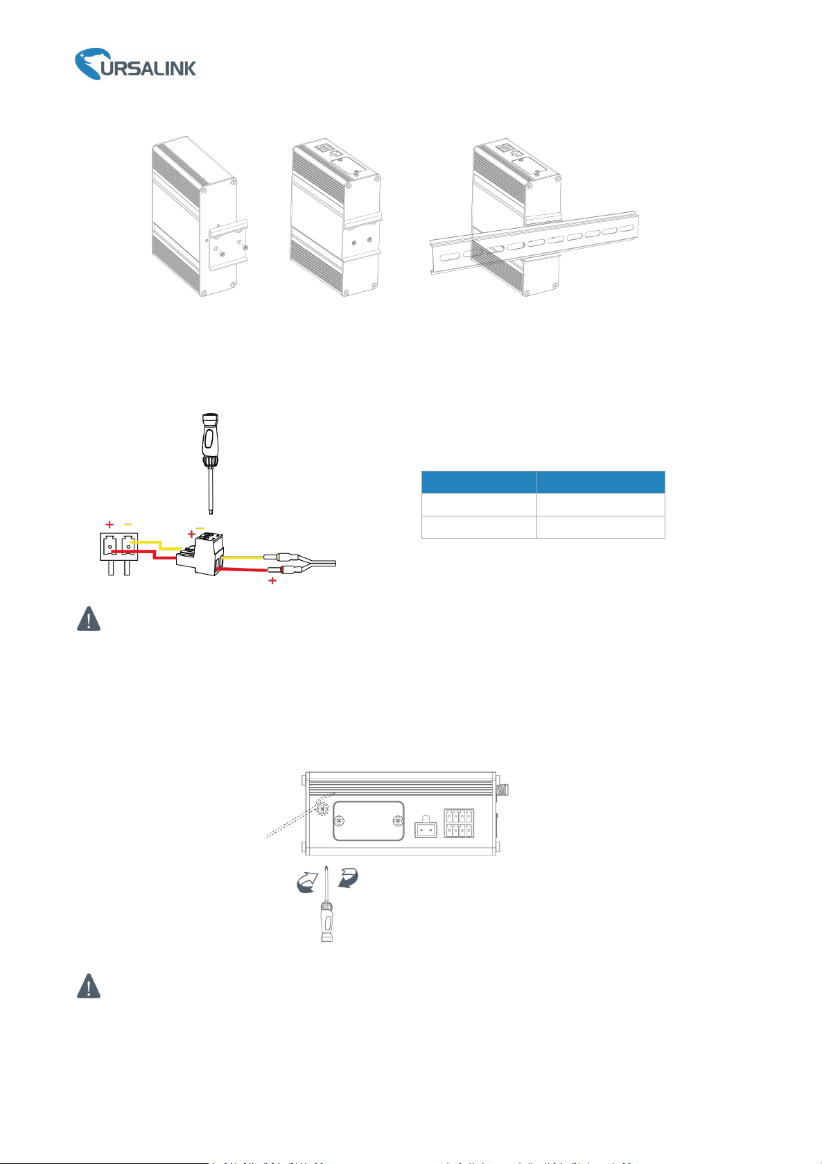
3.4 Mount the Router
The router can be placed on a desktop or mounted to a wall or a DIN rail.
3.4.1 Wall Mounting (Measured in mm)
Use 2 pcs of M3 × 6 flat head Phillips screws to fix the wall mounting kit to the router, and then use 2 pcs of
M3 drywall screws to mount the router associated with the wall mounting kit on the wall.
Recommended torque for mounting is 1.0 N·m, and the maximum allowed is 1.2 N·m.
3.4.2 DIN Rail Mounting (Measured in mm)
Use 2 pcs of M3 × 6 flat head Phillips screws to fix the DIN rail to the router, and then hang the DIN rail on
the mounting bracket. It is necessary to choose a standard bracket.
Recommended torque for mounting is 1.0 N·m, and the maximum allowed is 1.2 N·m.
Ursalink UR35 Quick Start Guide
www.ursalink.com
8
3.5 Power Supply Installation
A. Take out the terminal from the router and unscrew the bolt on terminal.
B. Screw down the bolt after inserting power cable into the terminal.
Connecting the Power Cable
If you insert wires into the reverse holes, the router will not start and you must switch the wires
into the correct holes.
3.6 Protective Grounding Installation
A. Remove the grounding nut.
B. Connect the grounding ring of the cabinet’s grounding wire onto the grounding stud and screw up the
grounding nut.
The router must be grounded when deployed. According to operating environment, the ground wire
should be connected with grounding stud of router.
Color
Polarity
Red
+
Yellow
-

Ursalink UR35 Quick Start Guide
www.ursalink.com
9
Getting Started
Please connect PC to any port among LAN1-LAN4 of UR35 router directly. PC can obtain an IP address, or
you can configure a static IP address manually. The following steps are based on Windows 10 operating
system for your reference.
(Note: As remote access is disabled by default, you can't access to the router's Web GUI if you connect PC to
WAN port of the router. But it will function properly if you enable it on the Web GUI.)
③Click “Ethernet” (May have different names). ④Click “Properties”.
4. PC Configuration for Web GUI Accessing to Router
①Click “Search Box” to search “Control Panel” on the
Windows 10 taskbar.
②Click “Control Panel” to open it, and then click
“View network status and tasks”.
Table of contents
Other Ursalink Network Router manuals

Ursalink
Ursalink UR75 Edge User manual

Ursalink
Ursalink UR32 User manual

Ursalink
Ursalink UR 51 User manual

Ursalink
Ursalink UR75 Edge User manual

Ursalink
Ursalink UR32 User manual

Ursalink
Ursalink UR55 User manual

Ursalink
Ursalink UR75 Edge User manual

Ursalink
Ursalink UR52 User manual

Ursalink
Ursalink UR 51 User manual


