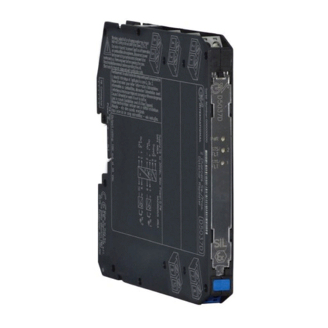
Vivace VRP10-O Quick guide

INSTALLATION, OPERATION AND CONFIGURATION MAN
UAL
September/2016
VRP10-O
PROFIBUS-PA OPTICAL REPEATER

VRP10-O PROFIBUS-PA OPTICAL REPEATER INSTALLATION, OPERATION AND CONFIGURATION MANUAL
2
COPYRIGHT
All rights reserved, including translations, reprints, complete or partial reproduction of this
manual, patent concession or model register of use/project.
No part of this publication may be reproduced, copied, processed or transmitted on any manner
or any medium (photocopy, scanning, etc.) without the express permission of Vivace Process
Instruments Inc., not even for training or electronic systems.
PROFIBUS
®
is a registered mark of PROFIBUS Nutzerorganisation.
We have reviewed this manual with great care to maintain compliance with the hardware and
software versions described herein. However, due to the dynamic development and version upgrades,
the possibility of technical deviations cannot be ruled out. We cannot accept any responsibility for the full
compliance of this material.
Vivace reserves the right to, without notice, make modifications and improvements of any kind in
its products without incurring in any circumstances, the obligation to make those same modifications to
products sold previously.
The information in this manual is frequently updated. Therefore, when using a new product,
please check the latest version of the manual on the Internet through our website
www.vivaceinstruments.com, where it can be downloaded.
You customer is very important for us. We will always be grateful for any suggestions for
improvements as well as new ideas, which can be sent to the e-mail: contato@vivaceinstruments.com
preferably with the title "Suggestions".
NOTE

VRP10-O PROFIBUS-PA OPTICAL REPEATER INSTALLATION, OPERATION AND CONFIGURATION MANUAL
3
SUMMARY
1
EQUIPMENT DESCRIPTION ......................................................................................................... 6
1.1.
IDENTIFICATION ........................................................................................................................................... 6
1.2.
TECHNICAL AND PHYSICAL SPECIFICATIONS ......................................................................................... 7
1.3.
INSTALLATION .............................................................................................................................................. 8
1.4.
HOUSING DIMENSION ............................................................................................................................... 10
1.5.
BLOCK DIAGRAM ....................................................................................................................................... 11
2
CONFIGURATION ........................................................................................................................ 12
2.1.
CONFIGURATION DETAILS AND INDICATIVE LEDS ............................................................................... 12
2.2.
CAPACITIVE GROUNDING ......................................................................................................................... 12
3
MAINTENANCE .......................................................................................................................... 13
1.1.
ORDERING CODE....................................................................................................................................... 13
4
ARRANTY ................................................................................................................................ 14
4.1.
GENERAL CONDITIONS ............................................................................................................................. 14
4.2.
WARRANTY PERIOD .................................................................................................................................. 14
APPENDIX ........................................................................................................................................ 15

VRP10-O PROFIBUS-PA OPTICAL REPEATER INSTALLATION, OPERATION AND CONFIGURATION MANUAL
4
1
It is extremely important that all the safety instructions, installation and operation in this manual are
followed faithfully. The manufacturer is not liable for damage or malfunction caused by improper use
of this equipment.
It is recommended to strictly following the rules and good practice relating to installation, ensuring
correct grounding, noise insulation and good quality cables and connections in order to provide the
best performance and durability to the equipment.
Special attention must be considered in relation to installations in hazardous areas, where
applicable.
ARNING
•Appoint only skilled people, trained with process and equipment;
•Install equipment only in operation compatible areas, with the proper connections and
protections;
•Use proper safety equipment for any handling device in field;
•Turn area power off before equipment installation.
SAFETY PROCEDURE
SYMBOLOGY
Caution – indicates risk or error source
Important Information
General or Specific Risk
Electric Shock Danger

VRP10-O PROFIBUS-PA OPTICAL REPEATER INSTALLATION, OPERATION AND CONFIGURATION MANUAL
5
GENERAL INFORMATION
Vivace Process Instruments ensures the operation of this equipment, according to the
descriptions contained in its manual, as well as technical characteristics, not
guaranteeing its full performance in particular applications.
The operator of this equipment is responsible for observing all aspects of safety and
prevention of accidents applicable during the execution of the tasks in this manual.
Failures that might occur in the system, causing damage to property or injury to
persons, shall additionally be prevented by external means to a safe outlet for the
system.
This equipment must be used only for the purposes and methods proposed in this
manual.
DATA SAVING
Whenever static data is changed via configuration, LCD will display icon, which will
be blinking until the save process is complete.
If user wishes to shut down the equipment, he must wait for the process to be finished.
If the equipment is shut down during saving process, a default will be performed, setting
default values in device parameters and the user must subsequently check and configure
those parameters according to his needs.

VRP10-O PROFIBUS-PA OPTICAL REPEATER INSTALLATION, OPERATION AND CONFIGURATION MANUAL
6
1 EQUIPMENT DESCRIPTION
Vivace VRP10 family of repeaters was developed for use in PROFIBUS-PA networks, allowing the
extension of these networks. VRP10-O allows the interface between IEC61158-2 standard bus and optical
fiber.
VRP10-O provides transmission via optical fiber with advantages such as electrical noise immunity,
reaching long distances in control systems topologies and the addition of ability to work with different ground
references.
It is powered by an external source of 24 Vdc. Connections, including power, grounding and PROFIBUS-
PA network are available via electrical terminals.
50/125 or 62.5 micrometers optical fiber cables with ST connectors can be used in single or dual
multimode.
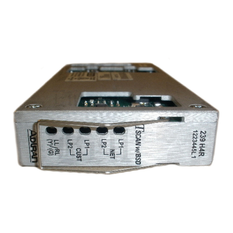
Three LEDs indicate the operating status and possible functional problems, as shown below.
Figure 1.1 - VRP10-O 2D front and side view drawing.
1.1. IDENTIFICATION
VRP10-O has an identification label on the
front face, specifying the model, manufacturer,
electrical connections and indicative LEDs as
shown on figure 1.1. It also has a side printed
diagram with all connections available and its
serial number.
PROFIBUS-PA connection indication using
optical fiber is also indicated on this label.
Figure 1.2 - Labels and diagrams for VRP10-O.

VRP10-O PROFIBUS-PA OPTICAL REPEATER INSTALLATION, OPERATION AND CONFIGURATION MANUAL
7
1.2. TECHNICAL AND PHYSICAL SPECIFICATIONS
The main technical and physical characteristics of VRP10-O are listed below. They are important
references that must be analyzed before installation and use into control system, especially regard to power
supply, temperature and mechanical connection.
Table1.1 - VRP10-O technical specification.
*only for DP/PA couplers with configurable slot time (eg. Siemens).

VRP10-O PROFIBUS-PA OPTICAL REPEATER INSTALLATION, OPERATION AND CONFIGURATION MANUAL
8
1.3. INSTALLATION
VRP10-O repeaters are easy to install and allow users to extend a PROFIBUS-PA segment up to 4 km
(2.5 mi). It can also be connected to different ground references, bringing an unprecedented advantage
once one of the major problems in digital network on the factory floor are just noise and current flowing
through the ground conductor due to ground differential between distant areas.
The figure below illustrates an application assembly between remote areas.
Occasionally, there might be adjustments in the PROFIBUS-DP master configuration, when
communication is not established successfully. The solution is setting TSL (time slot) and TTR (Token
Rotation Time). TSL is given in bit times and means the time PROFIBUS-DP master will wait for a slave
response before re-sending a frame or even send a new frame. TTR is given in bit times and is usually
calculated by the configuration tools. It is the time to pass the token across the network and return to its
original master. When working with multiple masters this includes the total time for each master to complete
its I/O cycle, pass the token to the next master and get token back to the original master. Some factors
directly influence the TTR: baud rate, number of slaves with cyclic data exchange, total number of I/O during
data exchange and quantity of masters.
It is possible to set several optical segments in cascade (a combination cable of PROFIBUS-PA + fiber
optics + PROFIBUS-PA cable). Eventually it might be necessary to adjust TSL and TTR parameters on
cyclic DP master configuration, as explained above. Figure below illustrates an application assembly
between remote areas.
Figure 1.3 - VRP10-O insulating control networks, allowing different ground references.

VRP10-O PROFIBUS-PA OPTICAL REPEATER INSTALLATION, OPERATION AND CONFIGURATION MANUAL
9
Figure below shows the VRP10-O side schematic setup and its terminals for connections.
Figure 1.4 - VRP10-O schematic side diagram.
The figure and table below show the repeater connections.
Figure 1.5 – Repeater frontal label. Table1.2 - List of terminal connections for the VRP10-O repeater.
STEP BY STEP INSTALLATION:
1) Fix the two repeaters in their respective control panel DIN rails.
2) Remove protective cover from optical channels.
3) Connect modules using standard ST optical fiber.
4) Connect grounding.
5) Connect PROFIBUS-PA channel.
6) Connect 24 Vdc power supply.
7) Supply a impedance source to PROFIBUS-PA segment.

VRP10-O PROFIBUS-PA OPTICAL REPEATER INSTALLATION, OPERATION AND CONFIGURATION MANUAL
10
Make sure the voltage source that feeds the impedance source has a current capacity for all PA
segment with the following minimum specifications: 24 Vdc ± 10%; Ripple < 50 mV p-p.
Ensure that the optical plug faces are free of dirt or other contamination source.
Make sure that an optical input is connected to an optical output (crossover connection) and that
the connector is firmly attached to the repeater socket.
Ensure there is enough strain relief in fiber optic cable and the minimum bending radius have been
met.
Keep repeaters sockets protected by with protective plugs when they out of use.
Always respect the maximum length specified in Chapter 1.2.
1.4. HOUSING DIMENSION
Figure 1.6 - VRP10-O dimensional drawing.

VRP10-O PROFIBUS-PA OPTICAL REPEATER INSTALLATION, OPERATION AND CONFIGURATION MANUAL
11
1.5. BLOCK DIAGRAM
The repeater components modularization is described in the following block diagram.
Figure 1.7 - Block diagram for VRP10-O.

VRP10-O PROFIBUS-PA OPTICAL REPEATER INSTALLATION, OPERATION AND CONFIGURATION MANUAL
12
2 CONFIGURATION
2.1. CONFIGURATION DETAILS AND INDICATIVE LEDS
VRP10-O is dedicated to the conversion of signals H1 (IEC61158-2) with fixed 31.25 kbits/s rate, so
there is no additional configuration needed for it. For convenience, there are three indicative LEDs.
Table 2.1 - VRP10-O indicative LEDs.
2.2. CAPACITIVE GROUNDING
VRP10-O also allows user to do the capacitive ground. With this possibility, user can connect a
capacitor (10 nF / 1500 V DC, internal to the repeater) to the ground.
Therefore, it is necessary to change the internal jumper position. The jumper is located in the
board just below the optical fiber plugs as shown in the figure below. Even in this condition, user
must connect the external ground reference in the terminal 8.
Figure 2.1 - Enabling the capacitive grounding.

VRP10-O PROFIBUS-PA OPTICAL REPEATER INSTALLATION, OPERATION AND CONFIGURATION MANUAL
13
3 MAINTENANCE
3.1. ORDERING CODE

VRP10-O PROFIBUS-PA OPTICAL REPEATER INSTALLATION, OPERATION AND CONFIGURATION MANUAL
14
4 ARRANTY
4.1. GENERAL CONDITIONS
Vivace ensures its equipments from any defect on manufacturing or component quality. Problems
caused by misuse, improper installation or exposure to extreme conditions are not covered by this warranty.
The user can repair some equipments by replacing spare parts, but it is strongly recommended to
forward it to Vivace for diagnosis and maintenance in cases of doubt or impossibility of correction by the
user.
For details about the product warranty, see the general term warranty on Vivace website:
www.vivaceinstruments.com.br.
4.2. ARRANTY PERIOD
Vivace ensures the ideal operating conditions of their equipment by a period of two years, with full
customer support regarding to installation, operation and maintenance for the best use of the equipment.
It is important to note that even after warranty period expires, Vivace assistance team is ready to
assist customer with the best support service, offering the best solutions for the installed system.

VRP10-O PROFIBUS-PA OPTICAL REPEATER INSTALLATION, OPERATION AND CONFIGURATION MANUAL
15
APPENDIX
FSAT
Technical Analysis Solicitation Form
Company: Unit/Department: Shipping Invoice nº:
Standard Warranty: ( )Yes ( )No Extended Warranty: ( )Yes ( )No Buying Invoice nº:
COMMERCIAL CONTACT
Complete Name: Position:
Phone and Extension: Fax:
e-mail:
TECHNICAL CONTACT
Complete Name: Position:
Phone and Extension: Fax:
e-mail:
EQUIPMENT DATA
Model: Serial Num.:
PROCESS INFORMATION
Environment Temperature (ºC) Work Temperature (ºC)
Min: Max: Min: Max:
Operation Time: Fail Date:
FAIL DESCRIPTION: Here user should describe in detail the observed behaviour of product, frequency of fail occurence and
repeatability. Also, should inform operational system version and a quick description of control system architecture where the
equipment was installed.
ADDITIONAL OBSERVATION:

VRP10-O PROFIBUS-PA OPTICAL REPEATER INSTALLATION, OPERATION AND CONFIGURATION MANUAL
16
Table of contents

