ADTRAN 239 H4R Instruction Manual

HDSL4 239 H4R Repeater
Installation and Maintenance Practice
Document Number: 61223445L2-5B
CLEI: T1R6189D_ _
June 2009
®

HDSL4 239 H4R Repeater Installation and Maintenance Practice
ii 61223445L2-5B
Front Matt er
Trademarks
Any brand names and product names included in this document are trademarks, registered
trademarks, or trade names of their respective holders.
To the Holder of this Document
The contents of this document are current as of the date of publication. ADTRAN®reserves the
right to change the contents without prior notice.
In no event will ADTRAN be liable for any special, incidental, or consequential damages or
for commercial losses even if ADTRAN has been advised thereof as a result of issue of this
document.
901 Explorer Boulevard
P.O. Box 140000
Huntsville, AL 35814-4000
(256) 963-8000
©2009 ADTRAN, Inc.
All Rights Reserved.
®

61223445L2-5B iii
Revision History
Conventions
The following typographical conventions are used in this document:
This font indicates a cross-reference link.
This font indicates screen menus, fields, and parameters.
THIS FONT indicates keyboard keys (ENTER, ESC, ALT). Keys that are to be pressed simultaneously
are shown with a plus sign (ALT+Xindicates that the ALT key and Xkey should be pressed at the
same time).
This font indicates references to other documentation and is also used for emphasis.
This font indicates on-screen messages and prompts.
This font indicates text to be typed exactly as shown.
This font indicates silk-screen labels or other system label items.
This font is used for strong emphasis.
NOTE
Notes inform the user of additional, but essential, information or
features.
CAUTION
Cautions inform the user of potential damage, malfunction, or
disruption to equipment, software, or environment.
WARNING
Warnings inform the user of potential bodily pain, injury, or death.
Revision Date Description
AJuly 2008 Initial release.
BJune 2009 Updated CLEI Code

HDSL4 239 H4R Repeater Installation and Maintenance Practice
iv 61223445L2-5B
Training
ADTRAN offers training courses on our products. These courses include overviews on product
features and functions while covering applications of ADTRAN product lines. ADTRAN
provides a variety of training options, including customized training and courses taught at our
facilities or at customer sites.
For inquiries concerning training, contact ADTRAN:
Training Phone: 800-615-1176, ext. 7500
Training Fax: 256-963-6700

61223445L2-5B v
Contents
Introduction . . . . . . . . . . . . . . . . . . . . . . . . . . . . . . . . . . . . . . . . . . . . . . . . . . . . . . . . . . . . . . . . . . . . . . . . . . . . . . 1
Description . . . . . . . . . . . . . . . . . . . . . . . . . . . . . . . . . . . . . . . . . . . . . . . . . . . . . . . . . . . . . . . . . . . . . . . . . . . . 2
Features . . . . . . . . . . . . . . . . . . . . . . . . . . . . . . . . . . . . . . . . . . . . . . . . . . . . . . . . . . . . . . . . . . . . . . . . . . . . . . 2
Basic Features . . . . . . . . . . . . . . . . . . . . . . . . . . . . . . . . . . . . . . . . . . . . . . . . . . . . . . . . . . . . . . . . . . . . . . 2
Enhanced Features . . . . . . . . . . . . . . . . . . . . . . . . . . . . . . . . . . . . . . . . . . . . . . . . . . . . . . . . . . . . . . . . . . 2
Isolation Relays . . . . . . . . . . . . . . . . . . . . . . . . . . . . . . . . . . . . . . . . . . . . . . . . . . . . . . . . . . . . . . . . . . 2
Ground Fault or Short Detection . . . . . . . . . . . . . . . . . . . . . . . . . . . . . . . . . . . . . . . . . . . . . . . . . . . . . 3
Electrical Characteristics . . . . . . . . . . . . . . . . . . . . . . . . . . . . . . . . . . . . . . . . . . . . . . . . . . . . . . . . 3
Compliance . . . . . . . . . . . . . . . . . . . . . . . . . . . . . . . . . . . . . . . . . . . . . . . . . . . . . . . . . . . . . . . . . . . . . . . . . . . . 4
Compatibility . . . . . . . . . . . . . . . . . . . . . . . . . . . . . . . . . . . . . . . . . . . . . . . . . . . . . . . . . . . . . . . . . . . . . . . . . . . 6
Installation . . . . . . . . . . . . . . . . . . . . . . . . . . . . . . . . . . . . . . . . . . . . . . . . . . . . . . . . . . . . . . . . . . . . . . . . . . . . . . . 7
Shipping Contents . . . . . . . . . . . . . . . . . . . . . . . . . . . . . . . . . . . . . . . . . . . . . . . . . . . . . . . . . . . . . . . . . . . . . . 7
Installing the Module . . . . . . . . . . . . . . . . . . . . . . . . . . . . . . . . . . . . . . . . . . . . . . . . . . . . . . . . . . . . . . . . . . . . . 8
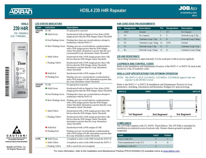
Front Panel LEDs . . . . . . . . . . . . . . . . . . . . . . . . . . . . . . . . . . . . . . . . . . . . . . . . . . . . . . . . . . . . . . . . . . . . . . . 9
Feature Details . . . . . . . . . . . . . . . . . . . . . . . . . . . . . . . . . . . . . . . . . . . . . . . . . . . . . . . . . . . . . . . . . . . . . . . . . . . 10
Fault Bridging . . . . . . . . . . . . . . . . . . . . . . . . . . . . . . . . . . . . . . . . . . . . . . . . . . . . . . . . . . . . . . . . . . . . . . . . . 10
Bad Splice Detection . . . . . . . . . . . . . . . . . . . . . . . . . . . . . . . . . . . . . . . . . . . . . . . . . . . . . . . . . . . . . . . . . . . 10
View Splice Results Screen . . . . . . . . . . . . . . . . . . . . . . . . . . . . . . . . . . . . . . . . . . . . . . . . . . . . . . . . . . . 11
Example . . . . . . . . . . . . . . . . . . . . . . . . . . . . . . . . . . . . . . . . . . . . . . . . . . . . . . . . . . . . . . . . . . . . . . . 11
Fast Retrain . . . . . . . . . . . . . . . . . . . . . . . . . . . . . . . . . . . . . . . . . . . . . . . . . . . . . . . . . . . . . . . . . . . . . . . . . . 12
Connections . . . . . . . . . . . . . . . . . . . . . . . . . . . . . . . . . . . . . . . . . . . . . . . . . . . . . . . . . . . . . . . . . . . . . . . . . . 13
HDSL4 Deployment Guidelines . . . . . . . . . . . . . . . . . . . . . . . . . . . . . . . . . . . . . . . . . . . . . . . . . . . . . . . . . . . 14
239 H4R Capacity Guidelines . . . . . . . . . . . . . . . . . . . . . . . . . . . . . . . . . . . . . . . . . . . . . . . . . . . . . . . . . . . . 14
Maintenance . . . . . . . . . . . . . . . . . . . . . . . . . . . . . . . . . . . . . . . . . . . . . . . . . . . . . . . . . . . . . . . . . . . . . . . . . . . . . 17
Specifications. . . . . . . . . . . . . . . . . . . . . . . . . . . . . . . . . . . . . . . . . . . . . . . . . . . . . . . . . . . . . . . . . . . . . . . . . . . . 18
Appendix A
Warranty . . . . . . . . . . . . . . . . . . . . . . . . . . . . . . . . . . . . . . . . . . . . . . . . . . . . . . . . . . . . . . . . . . . . . . . A-1
Warranty and Customer Service . . . . . . . . . . . . . . . . . . . . . . . . . . . . . . . . . . . . . . . . . . . . . . . . . . . . . . . . A-1
ADTRAN Sales . . . . . . . . . . . . . . . . . . . . . . . . . . . . . . . . . . . . . . . . . . . . . . . . . . . . . . . . . . . . . . . . . . . A-1
ADTRAN Technical Support . . . . . . . . . . . . . . . . . . . . . . . . . . . . . . . . . . . . . . . . . . . . . . . . . . . . . . . . . A-1
ADTRAN Repair/CAPS . . . . . . . . . . . . . . . . . . . . . . . . . . . . . . . . . . . . . . . . . . . . . . . . . . . . . . . . . . . . . A-1
Repair and Return Address . . . . . . . . . . . . . . . . . . . . . . . . . . . . . . . . . . . . . . . . . . . . . . . . . . . . . . . . . . A-1

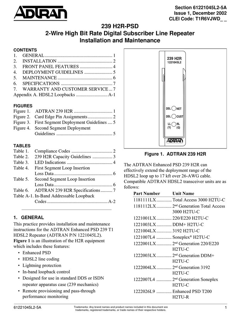
HDSL4 239 H4R Repeater Installation and Maintenance Practice
vi 61223445L2-5B
Figures
Figure 1. 239 H4R Front Panel . . . . . . . . . . . . . . . . . . . . . . . . . . . . . . . . . . . . . . . . . . . . . . . . . . . . . . . . . . . . 1
Figure 2. View Splice Results Screen . . . . . . . . . . . . . . . . . . . . . . . . . . . . . . . . . . . . . . . . . . . . . . . . . . . . . . 11
Tables
Table 1. 239 H4R Electrical Characteristics . . . . . . . . . . . . . . . . . . . . . . . . . . . . . . . . . . . . . . . . . . . . . . . . . . 3
Table 2. Compliance Codes . . . . . . . . . . . . . . . . . . . . . . . . . . . . . . . . . . . . . . . . . . . . . . . . . . . . . . . . . . . . . . 4
Table 3. Front Panel LEDs . . . . . . . . . . . . . . . . . . . . . . . . . . . . . . . . . . . . . . . . . . . . . . . . . . . . . . . . . . . . . . . 9
Table 4. 239 H4R Card Edge Pin Assignments . . . . . . . . . . . . . . . . . . . . . . . . . . . . . . . . . . . . . . . . . . . . . . 13
Table 5. 239 H4R Capacity Guidelines for ADTRAN Housings . . . . . . . . . . . . . . . . . . . . . . . . . . . . . . . . . . 15
Table 6. 239 H4R Capacity Guidelines for Other Housings . . . . . . . . . . . . . . . . . . . . . . . . . . . . . . . . . . . . . 16
Table 7. 239 H4R Specifications . . . . . . . . . . . . . . . . . . . . . . . . . . . . . . . . . . . . . . . . . . . . . . . . . . . . . . . . . 18

61223445L2-5B 1
HDSL4 239 H4R Repeater
INTRODUCTION
HDSL4 technology provides extended range T1 (DS1) transport on the telecommunications
network, and features spectral compatibility with ADSL and other transport technologies. The
ADTRAN HDSL4 239 H4R Repeater (239 H4R, P/N XXXXXXXLX) regenerates the HDSL4
signal, extending the range of the HDSL4 circuit. The 239 H4R has enhanced troubleshooting
capabilities in the presence of shorts or ground faults on the customer side of the repeater.
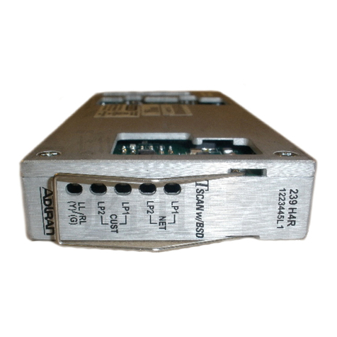
Figure 1 illustrates the 239 H4R (front panel).
Figure 1. 239 H4R Front Panel

HDSL4 239 H4R Repeater Installation and Maintenance Practice
261223445L2-5B
Description
The 239 H4R is designed for installation in pre-wired 239-sized outside plant (OSP) repeater
housings and apparatus cases. Up to three 239 H4R units work in conjunction with an
ADTRAN H4TU-C (HDSL4 Transceiver Unit for the Central Office) and an ADTRAN H4TU-R (T-
200 HDSL4 Transceiver Unit for the Remote End) to provide DS1 service on the local loop.
The H4TU-C unit receives DSX-1 input signals from the network through the chassis. It then
transports them across the HDSL4 circuit and terminates them through the H4TU-R unit,
which provides a traditional DS1 to customer equipment. The H4TU-C provides testing, provi-
sioning, and performance monitoring capabilities that address circuit status.
Features
The List 2 239 H4R has the same basic features as the List 1 239 H4R (P/N 61223445L1), and
enhanced features and capabilities.
Basic Features
The basic features of the 239 H4R include the following:
• TC PAM line coding
• Lightning protection
• In-band loopback control
• Standard 239 form factor repeater apparatus case design
• Bad Splice Detection (refer to “Bad Splice Detection” on page 10)
• Fast Retrain (refer to “Fast Retrain” on page 12)
•TSCAN
Enhanced Features
Enhancements include the following:
• Fault Bridging (refer to “Fault Bridging” on page 10)
• Ground Fault Segment Identification
• Loop-to-Loop Detection
• Isolation relays in the span-powering circuitry, between the network and customer sides of
the repeater.
• The ability to detect a ground fault or short on the customer side of the repeater.
Isolation Relays
Isolation relays are normally open without span powering. Once span powering is detected on
the network-side, the 239 H4R monitors the customer-side to determine if a short or ground
fault condition exists. If no short or ground fault is detected, the 239 H4R will close the relay,
allowing span powering to pass from the network to the customer side.

Introduction
61223445L2-5B 3
Ground Fault or Short Detection
If a short or ground fault is detected, the 239 H4R will keep the relays open and continue to
monitor the customer-side interface until the fault condition clears. During the fault
condition, the network-side of that repeater can function normally, allowing for synchroni-
zation and loopback/sectionalization testing up to that repeater.
While the short or ground fault condition is present on the customer side of the repeater, the
239 H4R places a nominal –37 VDC on the customer-side, and every three seconds, will
actively monitor the customer-side for the fault to clear. Once the 239 H4R detects that the
condition is clear, the relays close, allowing span powering to pass to the customer side.
NOTE
The isolation process is only possible if the apparatus case is
properly grounded.
Electrical Characteristics
That following table lists the electrical characteristics of all four input ports of the 239 H4R in
an unpowered state.
Table 1. 239 H4R Electrical Characteristics
Subscriber Loop Test Set Ohmmeter
T/R T-GND R-GND T/R T-GND R-GND
NET 1 5365K 365K NET 1 5.8 14.4M 15.6M
NET 2 5218K 217K NET 2 5.8 16.1M 16.5M
CUST 1 791.9K 91.9K CUST 1 5.7 24.4M 24.3M
CUST 2 661.2K 61.1K CUST 2 5.9 24.0M 23.8M

HDSL4 239 H4R Repeater Installation and Maintenance Practice
461223445L2-5B
Compliance
WARNING
Voltages up to –200 VDC with respect to ground and between
individual telecommunications conductors may be present.
The HDSL4 239 H4R Repeater (P/N XXXXXXXLX) is NRTL Listed to the applicable UL
standards. The HDSL4 239 H4R Repeater (239 H4R) meets or exceeds all the applicable
requirements of NEBS, Telcordia GR-63-CORE, and GR-1089-CORE. The 239 H4R is
intended for deployment in 239 form factor outside plant (OSP) apparatus cases and cabinets.
Table 2 lists the compliance codes for the 239 H4R.
This device complies with Part 15 of the FCC rules. Operation is subject to the following two
conditions:
1. This device may not cause harmful interference.
2. This device must accept any interference received, including interference that may cause
undesired operation.
Changes or modifications not expressly approved by ADTRAN could void the user’s authority
to operate this equipment.
CAUTION
Per GR-1089-CORE, the 239 H4R is designed and intended for
installation as part of a Common Bonding Network (CBN). The 239
H4R is not designed nor intended for installation as part of an
Isolated Bonding Network (IBN).
Table 2. Compliance Codes
Code Input Output
Power Code (PC) C C
Telecommunication Code (TC) X X
Installation Code (IC) A –

Introduction
61223445L2-5B 5
NOTE
The HDSL4 input and output ports are classified as Type 3 and 5,
as defined in Appendix B of GR-1089-CORE Issue 4, and meets the
lightning and power fault criteria with primary protectors that meet
any of the voltage limits of GR-974-CORE or GR-1361-CORE (i.e.,
carbon blocks, gas tubes, and solid state).
NOTE
Current limiting protectors are not required.

HDSL4 239 H4R Repeater Installation and Maintenance Practice
661223445L2-5B
Compatibility
The 239 H4R is used in conjunction with any T1.418-compliant, span-powering H4TU-C and
H4TU-R.
Due to span power limits, the number of 239 H4R units permitted in the circuit depends on
the type of H4TU-C in use. A 239 H4R provides DS1 transport on all revised resistance design
(RRD) 26 AWG loops, 24 AWG loops, or both. Three 239 H4R repeaters can be added to extend
the range of a loop.
The following criteria determines repeater placement:
• On single 239 H4R loops, consider the attenuation properties of the loop segment.
• For a circuit requiring two 239 H4Rs, satisfy both segment attenuation and segment DC
resistance requirements.
• For a circuit requiring three 239 H4Rs, satisfy all H4TU-C and H4TU-R hardware
requirements, segment attenuation, and segment DC resistance requirements.
Refer to the “HDSL4 Deployment Guidelines” on page 14 of this practice and the applicable
installation and maintenance practice for the H4TU-C being deployed.

Installation
61223445L2-5B 7
INSTALLATION
After unpacking the 239 H4R, inspect it for damage. If damage has occurred, file a claim with
the carrier then contact ADTRAN Customer Service. Refer to “Appendix A, Warranty” for
further information. If possible, keep the original shipping container for returning the 239
H4R for repair or for verification of shipping damage.
Shipping Contents
The contents include the following items:
• HDSL4 239 H4R Repeater (P/N 1223445L2)
•HDSL4 239 H4R Repeater Job Aid (P/N 61223445L2-22)
•HDSL4 239 H4R Repeater Compliance Notice (P/N 61223445L2-17)
CAUTION
Electrostatic discharge (ESD) can damage electronic modules.
When handling modules, wear an antistatic discharge wrist strap
to prevent damage to electronic components. Place modules in
antistatic packing material when transporting or storing. When
working on modules, always place them on an approved antistatic
mat that is electrically grounded.
C A U T I O N !
SUBJECT TO ELECTROSTATIC DAMAGE
OR DECREASE IN RELIABILITY.
HANDLING PRECAUTIONS REQUIRED.

HDSL4 239 H4R Repeater Installation and Maintenance Practice
861223445L2-5B
Installing the Module
The following are general installation considerations:
• To install the 239 H4R, refer to the installation and maintenance practice for the housing
in use.
NOTE
There are no manual option settings for the 239 H4R.
CAUTION
Ensure that the OSP repeater housing or apparatus case is
properly grounded.
• The H4TU-C provides power to the 239 H4R, independent of line impedance or wire gauge.
The span power from the H4TU-C is passed through the 239 H4R and can also span-power
additional H4Rs, the H4TU-R, or both. Refer to the “HDSL4 Deployment Guidelines” on
page 14.
• The 239 H4R is suitable for deployment in any environmentally controlled, 239-type
apparatus case. A retainer latch is available for securing the 239 H4R in the case.
• When the 239 H4R first powers up, it runs a power up self-test. Once the power up self-
test is complete, the status LEDs reflect the true state of the hardware (see Table 3).

Installation
61223445L2-5B 9
Front Panel LEDs
The 239 H4R provides front panel LEDs that display status information. Table 3 lists the 239
H4R LEDs and status descriptions.
Table 3. Front Panel LEDs
Label Status Description
LP1/LP2 NET {Off
zGreen
4Green, Fast Flashing
4Green, Slow Flashing
zYellow
4Yellow, Flashing
zRed
4Red, Flashing
No span power is present
Synchronized with an Signal-to-Noise Ratio (SNR)
margin greater than the SNR Margin Alarm Threshold
Flashing three times per second indicates attempt to
synchronize with the H4TU-C
Flashing once per second indicates synchronization with
a SNR margin greater than the SNR Margin Alarm
Threshold; attenuation is greater than the user
recommended Loop Attenuation Alarm Threshold
Synchronized with a SNR margin greater than 0 dB, but
less than the SNR Margin Alarm Threshold
Synchronized with a SNR margin greater than 0 dB, but
less than the SNR Margin Alarm Threshold; attenuation
is greater than the Loop Attenuation Alarm Threshold
Synchronized with a SNR margin of 0 dB
Flashing once per second indicates synchronization with
a SNR margin of 0 dB; attenuation is greater than the
Loop Attenuation Alarm Threshold
LP1/LP2 CUST {Off
zGreen
4Green, Fast Flashing
4Green, Slow Flashing
zYellow
4Yellow, Flashing
zRed
4Red, Flashing
No span power is present
Synchronized with an Signal-to-Noise Ratio (SNR)
margin greater than the SNR Margin Alarm Threshold
Flashing three times per second indicates attempt to
synchronize with the H4TU-R
Flashing once per second indicates synchronization with
a SNR margin greater than the SNR Margin Alarm
Threshold; attenuation is greater than the Loop
Attenuation Alarm Threshold
Synchronized with a SNR margin greater than 0 dB, but
less than the SNR Margin Alarm Threshold
Synchronized with a SNR margin greater than 0 dB, but
less than the SNR Margin Alarm Threshold; attenuation
is greater than the Loop Attenuation Alarm Threshold
Synchronized with a SNR margin of 0 dB
Flashing once per second indicates synchronization with
a SNR margin of 0 dB; attenuation is greater than the
Loop Attenuation Alarm Threshold
LL/RL zGreen
zYellow
4Yellow, Flashing
A loopback is active at the H4R towards the H4TU-R
A loopback is active at the H4R towards the H4TU-C
H4R is armed but not in loopback

HDSL4 239 H4R Repeater Installation and Maintenance Practice
10 61223445L2-5B
FEATURE DETAILS
The 239 H4R has the following operational features:
• Fault Bridging
• Bad Splice Detection
• Fast Retrain
•TSCAN
• Ground Fault Segment Identifier
• Loop-to-Loop Detection
Fault Bridging
The Fault Bridging feature minimizes downtime due to intermittent impairments that appear
on the cable pair, for example, from a Ground Fault Interrupt (GFI), short, micro-interruption,
bad splice, or noise burst. This feature allows the DSL transceivers to maintain synchroni-
zation during an interruption, thus avoiding a 25 to 30-second retrain. Depending on the type
of impairment, interruptions up to 200 ms can be bridged.
Bad Splice Detection
This 239 H4R supports the Runtime TScan 2.0™ Bad Splice Detection (TScan w/BSD)
feature, an ADTRAN proprietary, non-intrusive algorithm for detection of anomalies (bad
splices) in the copper plant. This feature monitors the cable pair during runtime for the
presence of bad splices that can potentially impact service.
Poor cable splices are often undetected by normal testing methods. Often, these splices
present no problem for the data transmission equipment until oxidation with the splice itself
causes a rapid impedance change, which can cause errors, signal margin fluctuation, and
retrain of the DSL transceivers. The splice detection feature is available from the Trouble-
shooting Screen through the craft access port.
Data transmission transceivers (especially echo-cancelled technologies) are subject to perfor-
mance degradations and errors in the presence of bad splices. A splice may be benign for a
time, allowing a circuit to behave appropriately for portions of the day. However, over time the
splice oxidizes and incurs small, rapid changes in impedance. This inconsistency in behavior
makes the problem difficult to locate. Additionally, an impedance change that is large enough
to cause the transceiver trouble can still be small enough to be undetectable by test
equipment used on the copper pairs. Therefore, a non-intrusive method of identifying these
bad splices has been developed to aid the customer in troubleshooting the distribution plant.
NOTE
The Splice Detection Feature is a troubleshooting aide. Due to
inconsistency in environmental conditions and their effect on
telecommunications plant, ADTRAN cannot guarantee the
accuracy of the measurements. Comparison to existing engineering
drawings can provide exact locations of suspect splices indicated
by ADTRAN algorithms.

Feature Details
61223445L2-5B 11
Splices that are varying in impedance cause the HDSL data pump to see a reduced and/or
fluctuating signal quality (margin). The HDSL data pump attempts to track these changes.
When the changes become too severe, errors or loss of synchronization result.
View Splice Results Screen
Access to the Bad Splice Detection feature is through the Troubleshooting screen, using the
craft access terminal of the H4TU-C or H4TU-R. Selecting the View Splice Results option from
the Troubleshooting screen menu displays the View Splice Results screen (see Figure 2). The
Splice Detection Results column lists the reported results for each transceiver:
• NTF - Indicates that the unit is active and has not detected any problems, or, the number
of detected anomalies have not yet reached the detection count threshold. This threshold
facilitates the reporting of the result to this screen (eight is the present threshold).
• LOS - Indicates that the unit has not detected the remote unit.
• Number - Indicates if the number of times an anomaly was detected exceeds the detection
count threshold of eight. The number in this column represents the number of feet from
the transceiver (Reference Point) to the anomaly. This number also reflects the highest
anomaly count the unit sees, as it is possible to have more than one bad splice per circuit.
This screen reports the worst (most frequently detected) anomaly.
Example
In Figure 2, the View Splice Results screen example shows that a detection has occurred
approximately 650 feet from an H4TU-C module on Loop 2 of the HDSL4 circuit.
Figure 2. View Splice Results Screen
Circuit ID:HTSVALHDSL4 MM/DD/YY hh:mm:ss
Press ESC to return to previous menu
* Note: Chronic Circuit Results are only valid after all other circuit *
* qualification tests have been performed and failed to show a trouble !! *
Splice Detector Version 1 Result Definitions:
---------------------------------------------
NTF - No Trouble Found yet.
LOS - Unit not in sync.
Number - Distance from Reference point (in ft.) of suspect splice.
Reference Splice Detection Results Version Result Shown
Point Loop 1 Loop 2 Number for date
--------- ---------- ---------- ------- MM/DD/YY
H4TUC NTF 650 01 --------
H4TUR NTF NTF 01 06/17/04
H4RU1 NET NTF NTF 01
H4RU1 CST NTF NTF 01 (B)Back

HDSL4 239 H4R Repeater Installation and Maintenance Practice
12 61223445L2-5B
Fast Retrain
Fast Retrain is an ADTRAN-proprietary feature that minimizes downtime when an inter-
mittent, non-power related impairment (bad splice, noise burst, etc.) affects the HDSL loop
and cannot be bridged.
When such an impairment occurs after achieving HDSL synchronization, Fast Retrain is
invoked to restore service within 5 to 7 seconds. This short retrain time allows for reduced
downtime compared to the traditional 25 to 30 second retrain duration.
NOTE
For proper functionality, install Fast Retrain capable units on both
ends of the circuit. Failure of a Fast Retrain attempt initiates the
traditional (25-30 second) retrain.
HDSL2 and HDSL4 transceivers normally train in approximately 25 to 30 seconds (for initial
turnup, this time frame should be acceptable). However, once service has been established on
the circuit, any large down-time will interrupt communications on the circuit. A loss of
synchronization on the HDSL loop can cause excessive down times due not only to the 30-
second HDSL retrain time, but also further delays due to the higher level protocols in the
network going through re-synchronization. On the older generation HDSL2 and HDSL4 units,
a 1-second loss of HDSL frame synchronization would cause the data pumps to retrain. This
retrain would take approximately 25 seconds during which AIS would be sent to the termi-
nating equipment. The reception of AIS by the terminating equipment then might trigger
higher level protocol re-synchronizations.
In an effort to minimize this down time, the Fast Retrain feature has been implemented. If an
impairment (bad splice, for example) causes the HDSL data pump to lose frame synchroni-
zation for 500 msec or longer, instead of retraining, the system attempts a Fast Retrain. This
abbreviated train can achieve data mode in 5 to 7 seconds. A successful fast retrain should be
evident by watching the Span Status screen and by reduced unavailable seconds (UAS) in the
PM data for each LOS alarm recorded.

Feature Details
61223445L2-5B 13
Connections
All connections take place through card edge connectors.
Table 4 provides the card edge pin assignments.
CAUTION
The 239 H4R dissipates a maximum of 5.4 watts.
CAUTION
Ensure that the chassis ground is securely connected to the OSP
apparatus case. Table 4 lists the ground pin designations.
Table 4. 239 H4R Card Edge Pin Assignments
Pin Designation Description
1GND Ground
2NC No Connect
3T1 Customer Loop 1 Tip
4R1 Customer Loop 1 Ring
5T1 Network Loop 1 Tip
6R1 Network Loop 1 Ring
7NC No Connect
8TNetwork Loop 2 Tip
9 R Network Loop 2 Ring
10 GND Ground
11 TCustomer Loop 2 Tip
12 RCustomer Loop 2 Ring

HDSL4 239 H4R Repeater Installation and Maintenance Practice
14 61223445L2-5B
HDSL4 Deployment Guidelines
Refer to the applicable H4TU-C installation and maintenance practice, HDSL4 Deployment
Guidelines section, for loop parameters, including attenuation and loop resistance consider-
ations.
NOTE
The H4TU-C with part numbers 1221401L6, 1221403L6, and
1221404L6 support only one 239 H4R in the HDSL4 circuit.
Refer to the Detailed Status Screen by accessing the menus on the H4TU-C craft terminal
interface for current Signal-to-Noise Ratio Margin and Attenuation status indications for the
circuit.
239 H4R Capacity Guidelines
The 239 H4R is designed for installation in a prewired apparatus case. Table 5 and Table 6
define the capacity guidelines for deployment. The housing capacity numbers are based on
testing results.
Other manuals for 239 H4R
2
This manual suits for next models
1
Table of contents
Other ADTRAN Repeater manuals

ADTRAN
ADTRAN NetVanta FT1 Maintenance and service guide

ADTRAN
ADTRAN 1223445L2 User manual

ADTRAN
ADTRAN HDSL4 T200 H4TU-R Product manual

ADTRAN
ADTRAN 239 T1 Instruction Manual

ADTRAN
ADTRAN 239 H2R-PSD Instruction Manual

ADTRAN
ADTRAN T200 T1 HDSL4 Instruction Manual

ADTRAN
ADTRAN 239 H4R Instruction Manual

ADTRAN
ADTRAN D4-U-RPM Maintenance and service guide