Vivaldi MZ6120 BTK User manual

MZ6500BTK
BM6
Multizone amplified mixer with built-in sources
FM radio/ Keysol / MP3 / USB / SD / Bluetooth
ATTENTION!
Read carefully this manual before installation and using.
Damage caused by incorrect installation and/or improper use will not be
covered by the warranty
M
Z6120
BTK
M
Z6240
BTK
M
Z6350
BTK
TECHNICAL
MANUAL
installation
and
use


INDEX
1. Safety information p. 2
2. Introduction p. 3
3. Front panel p. 4
4. Rear panel p. 5
5. 100V speakers connection p. 7
6. Multi zone microphone base BM6 p. 7-8
7. Connection schematics base BM6 p. 10
8. Connection schematics with BM1000D, GRM1 p. 11-12
9. Example with evacuation and alert messages p. 11
10. Built-in sources working details p. 12-13
11. Start up procedure p. 13
12. Technical specification p. 14th
13. Warranty p. 15
1 Safety information
1. Read and keep these instructions.
2. Pay attention to the safety information and follow the indications
3. Do not use the appliance near liquids, gases and corrosive elements.
4. Do not install near heat sources such as radiators, cookers, stoves or heat sources in general.
5. Do not block the ventilation holes. Install according to the instructions in this manual.
6. The supplied power plug is equipped with an earth connection. Use a grounded power outlet for personal safety.
7. Protect the power cord from being walked on or pinched, particularly at plugs, sockets, and the outlet from the apparatus.
8. For racking, use the fins supplied and the SR500 side supports. When using a cart, use caution and avoid tipping.
9. Unplug this apparatus during lightning storms or when unused for long periods of time.
10. It is forbidden to open the device. It is forbidden to tamper with the internal parts or the internal wiring.
11. The warranty is void if the failure depends on inexperience or negligence, tampering, fortuitous events or force majeure.
WARNING!

2 INTRODUCTION
The multi-zone, 6-zone powered mixers of the MZ series with FM radio, Keysol, USB, Micro SD and Bluetooth have a power of
120W (MZ6120BTK), 240W (MZ6240BTK), 350W (MZ6350BTK) or 500W (MZ6500BTK). They are to be used in environments
with a large number of loudspeakers, where the same music (sound system) is required with independent volume adjustment on
the zones. For example restaurants, bars, offices, banks, places of worship, etc...
The multi-zone powered mixers of the MZ series are designed to offer maximum protection against overloads, short circuits and
overheating to avoid any type of damage to people or things.
IMPORTANT: the sum of the powers of the 100V loudspeakers connected to the 6 amplifier outputs MUST NEVER EXCEED
THE NOMINAL POWER OF THE AMPLIFIER ITSELF.
ATTENTION: this series of amplifiers only requires 100V audio speakers. Connecting 8 ohm audio speakers can cause serious
damage.
Notes: Choose the amplifier according to the total power needed 120W (MZ6120BTK), 240W (MZ6240BTK), 350W
(MZ6350BTK) or 500W (MZ6500BTK).
It should be noted that the total power of the amplifier is divided between the zones.
For example, if the 240W MZ6240BTK is chosen and nominal 200W loudspeakers are connected to ZONE 1, while nominal 40W
loudspeakers are connected to ZONE 2, the power of the amplifier must be considered saturated. You will not be able to connect
other speakers to ZONE3/4/5/6.
Features
• Compact, all-in-one, 6-zone, public address 100V multi-zone amplified mixer with integrated sources.
• Independent volume adjustment on each zone.
• Vocal messages, selective or general, via BM6 microphone bases (max 6).
• Voice messages, general, via microphone base BM1000D.
• USB/Micro SD Mp3 Player (front panel ports), FM Radio, Keysol and Bluetooth.
• Microphone inputs for microphones, microphone bases, wireless microphones.
• Integrated 100V transformer.
• Output power 120W/240W/350W/500W (depending on the model).
• Speaker output at 100V.
• IR remote control supplied to control USB, Micro SD, FM radio and Bluetooth functions.
• LED indicators for power, clip, protect and signal.
• 6 mixable inputs + sources + priority emergency input + multizone microphone base.
• CH1 (priority): mic JACK 5-8mV 600Ω.
• CH2-3-4: XLR 5-8mV 600 mic Ω phantom power (selectable) / line XLR 150-470mV 10KΩ (switchable).
• CH5-6: RCA lines.
• CH7 EMC: priority emergency input for evacuation or service messages.
• CH8: BM6 multi-zone microphone base input paging.
• Adjustable MUTE function.
• RCA line out: 0.775V (0dBV) output dependent on input channels and independent of volume.
• 75Ω antenna for FM RADIO reception.
• Treble/bass tone control. Short circuit, clip, overload and overheat protection.

3 FRONT PANEL
1. Power switch.
2. General volume adjustment.
3. Treble adjustment.
4. Bass tone adjustment.
5. Talkover sensitivity adjustment
6. LINE 6 input volume adjustment.
7. LINE 5 input volume adjustment.
8. MIC/LINE4 input volume adjustment.
9. MIC/LINE3 input volume adjustment.
10. MIC/LINE2 input volume adjustment.
11. MIC1 input volume adjustment.
12. MIC1 Jack input
13. USB port.
14. IR remote control receiver.
15. Settings and Enter key.
16. Play/Pause - Stop button.
17. Volume adjustment key, source/track change.
18. Mode change key.
19.SD card slot
20. All zone selection key.
21. ZONE1 volume adjustment.
22. ZONE1 On-Off selector.
23. ZONE2 volume adjustment.
24. ZONE2 On-Off selector.
25. ZONE3 volume adjustment.
26. ZONE3 On-Off selector.
27. ZONE4 volume adjustment.
28. ZONE4 On-Off selector.
29. ZONE5 volume adjustment.
30. ZONE5 On-Off selector.
31. ZONE6 volume adjustment.
32. ZONE6 On-Off Selector.

4 REAR PANELS
1. RJ45 socket for connecting the BM6 microphone base
2. Pre-out for connecting additional power amplifiers.
3. EMC input: Priority input for connecting message generators (GRM1)***.
4. LINE6 Input: Line level stereo RCA
5. LINE5 input: Line level stereo RCA
6. Input 4 level and phantom setting DIP Switch
7. Input 4: Settable balanced XLR
8. Input 3 level and phantom setting DIP Switch
9. Input 3: Settable balanced XLR
10. Input 2 level and phantom setting DIP Switch
11. Input 2: Settable balanced XLR
12. Zone 6 100V output
13. Zone 5 100V output
14. Zone 4 100V output
15. Zone 3 100V output
16. Zone 2 100V output
17. Zone 1 100V output
18. 230V power input
19. General output 4Ohm-8Ohm, 50V, 70V and 100V**
20. RJ45 Ethernet TCP/IP connector to connect to the LAN network
21. SMa connector for WiFi antenna
22. FM radio antenna connector
**IMPORTANT: you cannot use this amplifier by simultaneously connecting low impedance speakers (4, 8, 16Ω) and
70/100V.
It is possible to simultaneously connect 100V speakers both on the general output sockets (19) and on the zone sockets
(12, 13, 14, 15, 16, 17). It is recommended to connect as many audio speakers, as necessary, with a combined wattage not
exceeding 90% of the rated power of the amplifier.
If you connect the GRM1 device to the EMC input to send alarm or evacuation messages, the MUTE potentiometer (5)
must be adjusted to a minimum.
When connecting the GRM1 to the EMC input, use both the Left and Right outputs.
Clamp H for the hot pole and G for the screen. The C terminal must remain unconnected.

5 CONNECTION AUDIO SPEAKERS 100V
System with 100V line
Connect the speakers via a polarized cable, making a parallel connection, respecting the COM (-) and 100V (+) polarity.
A 100V speaker system can include many speakers connected to each other. The factor that determines how many speakers can
be connected to a single amplifier is the rated power. The sum of the rated powers of the speakers must not exceed the total
power of the amplifier.
Inmost uses, it is recommended to connect all the necessary audio speakers, so that the sum of the powers does not exceed
90% of the nominal power of the amplifier.
For example:
•108W MZ6120BTK
•216WMZ6240BTK
•315WMZ6350BTK
•450WMZ6500BTK
The terminals of a 100V audio speaker are connected to a transformer. The transformer has several nominal power take-offs.
Power sockets can be used to choose the wattage (and output volume) of each speaker to get the correct total power (supported
by the amplifier).
Amplifier output terminals for connecting audio speakers:
- 6 outputs at 100V
Audio speakers with different power ratings can be connected to each amplifier output (ZONE). The sum of
the nominal watts of the speakers must not exceed the power of the amplifier.
Failure to comply with this may result in permanent damage to the amplifier.

100V SPEAKER CONNECTION DIAGRAM

6 MULTI-ZONE MICROPHONE BASE BM6
Multi-zone microphone base, paging, remote, tabletop, with buttons, for amplifiers MZ6120BTK, MZ6240BTK, MZ6350BTK ,
MZ6500BTK .
The base provides 6-zone calling, with a maximum distance of 300 meters via CAT6 cable. Each amplifier supports up to 6
microphone bases, connected in cascade (daisy chain). The microphone bases have rear dipswitches for setting address,
priority and activating the chime tone.
The microphone base is powered directly by the amplifier.
Features:
6 zone selection buttons (ZONE1, ZONE2, ZONE3, ZONE4, ZONE5, ZONE6). -
Gooseneck microphone connector.
- Power indicator.
- Communication indicator.
- Busy indicator .
- Speaker zone selectors 1-6.
- Call/talk button.
- Select button to all zones (1-6 selector).
- ON/OFF switch.
- RJ45 port to connect the next base in cascade.
- RJ45 port of communication with amplifier MZ6120BTK, MZ6240BTK, MZ6350BTK , MZ6500BTK.
- Microphone gain control.
- Local Aux input (switching with microphone).
- Dip switch setting switches.
- 41cm rod.
- Power supply via amplifier link with CAT6 cable RJ45 connector.
- Linkable in daisy chain (up to 6 bases) for a maximum length of 300mt.
FRONT PANEL BACK PANEL
1 Gooseneck microphone connector.
2 Power indicator.
3 Indicator (chime) tone playback.
4 Indicator (busy) line engaged.
5 Speaker zone indicators 1-6.
6 Speaker zone selectors 1-6.
7 Call/talk button.
8 Select button to all zones (1-6 selector).
9 ON/OFF switch.
10 RJ45 port to connect the next base in cascade.
11 RJ45 port of communication with the MZ amplifier.
12 Microphone gain control.
13 Aux input (excludes microphone).
14 Dip switch switches configuration (see page 8).

Up to 6 BM6 microphone bases can be connected to the MZ6xxxBT amplifier, cascading with each other.
The setting of the address and priority, through the rear dip switches (see table), must take place before turning on the amplifier,
so that once turned on, the amplifier will detect the presence of the bases and their setting.
If the priority dipswitch is not set, all bases have the same priority, and the first one that makes the call, occupies the line.
If the priority dipswitch is set, the base station can interrupt ongoing communication and occupy the line.
In case of two or more bases with the same priority, the new call stops the current ones.
Making a microphone call, even in one area, still stops playing music in all other areas.
DIP1 –DIP4: microphone base address setting
DIP5 –DIP7: if set to "OFF" a press of the CALL button opens the communication and a subsequent press closes it. If set to the
"ON" position, you must hold down the CALL button to make the call.
DIP8: enabling or disabling tone din don.
IMPORTANT: before speaking, wait until the red collar of the microphone is lit.

7 CONNECTION DIAGRAM WITH BM6 BASE

8 WIRING DIAGRAM WITH BM1000D, GRM1
RECORDER, MESSAGE GENERATOR

9 EXAMPLE IN PLACE OF WORSHIP WITH MESSAGE
EVACUATION ALERT
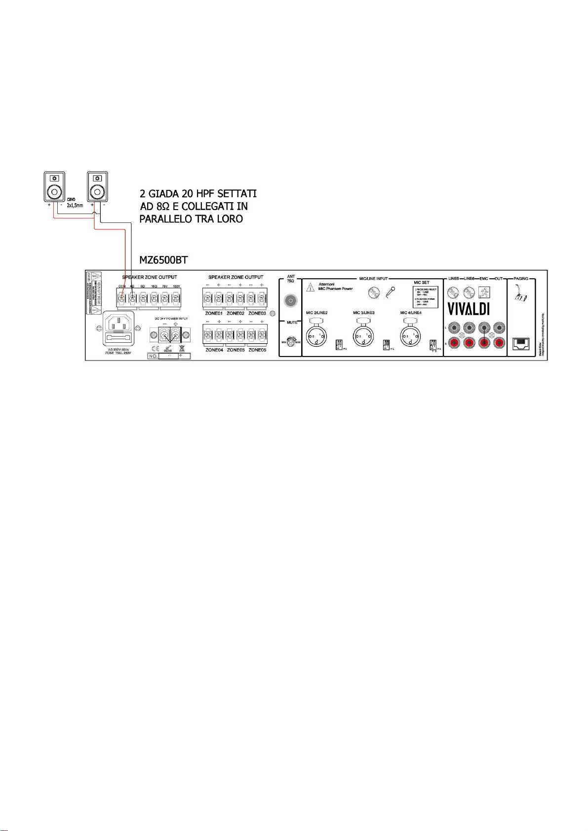
10 EXAMPLE OF CONNECTION WITH LOW IMPEDANCE
SPEAKERS
GRM1 main technical characteristics.
Possibility to create musical jingles as messages.
Possibility to link WebRadio with Timer.
Possibility to create nodes with music sequences / radio web links / messages as desired.
Activation of messages through contacts (timers or security systems such as fire fighting or
surveillance). Number of recordable messages: 100.
Total time: 120 minutes.
16GB internal memory.
Reading multimedia files: MP3, FLAC, WAV.
Internal scheduler for time/days/weeks/months timer programming.
1 LAN input for network connection (management interface for files, schedules and contacts).
Remote updates.
8 contacts in Input for activating messages, in order of priority (1st = max priority, 8th = min priority) 1
microphone input for message recording, button on the front.
1 Output contact for activation of equipment with priority contact.
Function keys: volume +/-, mic, stop.
Equipped with a backup battery, in case of power failure it maintains the programming.

10 SOURCE FUNCTIONS DETAIL
USING BLUETOOTH:
1. Turn on the device with the POWER button (1)
2.Press the MODE button repeatedly (13) until BT DISCONNECTED appears in the display
3. Turn on Bluetooth on your smartphone (or any other device that can stream music via Bluetooth) and search for new devices
4. In the list of detected devices select "ULISSE"
If you are prompted for a PIN, enter 2022.
5. Check that the amplifier display says "BT CONNECTED"
6. Stream music from your Device to the amplifier
7.Adjust the volume with the Prev/V-(12) and Next /V+(12) buttons
USING THE USB/SD READER:
1. Turn on the device with the POWER button (1)
2. Insert the USB stick, the device will activate auto play.
3. If you change source to select the USB player again, press the MODE button repeatedly (13)
4. With the PLAY button (11) you can pause and restart the song listening to
5. With the Prev/V-(12) and Next /V+(12) keys you can skip to the next or previous song (short press) or adjust the volume (long press)
6. With the SET button (10) you can scroll through the folders contained in the USB stick. An additional press allows you to access the playback
settings.
USING THE FM TUNER:
1. Turn on the device with the POWER button (1)
2. Press the MODE button repeatedly (13) until the RADIO appears in the display
3. With the Prev/V-(12) and Next /V+(12) buttons you can change radio station (short press) or adjust the volume (long press)
USING THE KEYSOL SOURCE
1. Turn on the device with the POWER button (1)
2. Press the MODE button repeatedly (13) until the WIFI AUDIO button appears in the display
3. Download the Jupiter KEYSOL application, click on the "+" button and follow the wizard.
By connecting the Ethernet cable amplifier to the same network as your smartphone, the KEYSOL module will automatically be visible
in the list of devices.
Open the Jupiter KEYSOL app, playsongs from the shared library, or select the desired function from the menu on the left.
SSID: Keysol_xxxx (e.g. Keysol_1234)
Password: vivaldi1234
For added network security we recommend
Change your password.
1
F
A
N
R
Repeat Branor
Shuffle (all songs, all folders)
Shuffle songs in the folder
Continuous playback
Ends playback after the last song in the folder.
Note: If the feature is selected in the last story of the folder, it will be active from the next folder

11 START-UP PROCEDURE
USING THE AMPLIFIER
After correctly connecting the audio speakers and any accessories (external sources, microphones, recorder / message generator,
etc.) proceed to start the device as follows:
1. Set the channel volume and general controls to 0 (zero).
2. Power the amplifier and turn it on.
3. Select the desired source with the 11 (MODE) button.
4. Increase the volume by holding down the 16 (+ volume) button until the threshold of 20 is exceeded.
5. Increase the overall volume with knob 2 (MASTER).
In the RJ45 input, connect the microphone base (e.g. BM6).
In the inputs MIC1 (front), MIC/LINE2, MIC/LINE3, MIC/LINE4 (back) connect external sources or microphone base, radio/wire
microphones (e.g. BM1000D/WSH/WSL/PG).
Important:
The MIC1 input on the front is prioritized, automatically attenuates the volume of internal sources and MIC/LINE2, MIC/LINE3,
MIC/LINE4 inputs (rear).
Adjust the desired MIC volume using knob 10 (MIC 1). The minimum level of background music is adjusted by the potentiometer
(point 12 page 5).
To connect a GRM1 recorder, message generator (alert, service, advertising) use the EMC IN.
For any other sources use the available channels MIC / LINE2, MIC / LINE3, MIC / LINE4 (back), setting the relative DIP SWITCH
in ON LINE position, adjusting the volumes through the knobs INPUT 2, INPUT 3, IMPUT 4.
If you use microphones that require Phantom power (+48V) activate it by putting the DIP SWITCHES in the OFF position.
In addition to the MASTER channel and volume controls, there are BASS (low frequencies) and TREBLE EQ (medium-high
frequencies) controls.
Adjust these controls according to the type of audio signal, the desired sound and the volume used (avoiding distortion).
Notes:
when adjusting the volume with the zone controls (1-6) and the Master, be careful not to saturate the signal of the device.
Saturation can also be done by adjusting the volumes of the input channels MIC1, MIC/LINE2, MIC/LINE3, MIC/LINE4 (front).
Saturation can also occur by mistakenly connecting a line signal into a microphone input.
The device will signal the volume limit threshold by turning on the 0dB or CLIP LEDs, placed on the front, which indicate
distortion or clipping of the output signal.
In case of prolonged lighting of the LEDs, immediately lower the MASTER, to avoid damaging the luminaire.

12 TECHNICAL SPECIFICATIONS
Model
MZ6120BTK
MZ6240BTK
MZ6350BTK
MZ6500BTK
Description
Multi-zone amplified mixer with built-in sources: FM / MP3 / USB / SD / Bluetooth remote control
included. Independent volume adjustment on 6 zones.
Selective or general messages via microphone base.
Nominal power
120W
240W
350W
500W
Speaker outputs
6 independent outputs at 100V
Connectors
Input Mic1 Jack 6,3mm
2-3-4 XLR balanced inputs, Mic/Line selectable, Phantom 48V ON/OFF Line inputs
5-6 with RCA
EMC emergency priority entry
Line out with RCA
PAGING for RJ45 microphone base
Controls
Tone controls ± 8 dB
Inputs
Mic1-4: 2.5mV, Line1-2: 250mV; EMC: 250mV
Line Output Level (REC)
0.775 (0dBV)
Frequency response
80Hz-16kHz
S/N Ratio
>70dB
THD
< 0.1%
Protection
Short circuit, clip, overload and overheating
Maximum consumption
200W
400W
500W
650W
Feeding
AC 230V, 50-60Hz / 24V DC
Dimensions mm
Dimensions 484x88x405 mm (WxHxD)
Weight
8.6 kg
9.4 kg
9.80 kg
10.25 kg
13 WARRANTY
ITALY: the document that certifies the guarantee is the sales invoice. The validity of the warranty of a product will be ascertained
exclusively by the VIVALDI SERVICE CENTER. The warranty period will last 12 months, from the date of delivery of goods. The
products and packaging at the time of return must not be tampered with. VIVALDI SRL will undertake to replace or repair the parts
constituting the supply, which are defective, provided that this does not depend on inexperience or negligence, tampering,
unforeseeable events or force majeure. The work related to repairs or replacements underwarranty will be carried outby VIVALDI
CUSTOMER SERVICE (0421.307825 int. 4) in the factory, or on site without this implying any responsibility on the part of Vivaldi
srl for direct or indirect damages suffered by the customer due to this. Where operational reasons require the equipment to be
repaired on site, the customer is responsible for the costs of transfer and stay off-site of the technical staff, which will be charged
with a regular invoice. In case of non-compliance with one or more of the rules listed above, the warranty is void.
Note: requests for return authorization for repair must be sent by filling out the following form https://vivaldigroup.it/it/rma.
The CUSTOMER SERVICE ([email protected] or 0421.307825 int. 4) will send by email, after technical evaluation of the fault,
the return authorization number and the procedure to be followed.
OTHER COUNTRIES: 12-month warranty terms. The term and warranty may vary by country and may not be the same for all
products. Warranty terms and conditions for a particular product can be determined first by locating the appropriate country where
the product was purchased, and then identifying the type of product.
Vivaldi, in its constant commitment to improve its products, reserves the right to make technical and aesthetic changes
without prior notice.

VIVALDI SRL division of VIVALDI UNITED GROUP
Registered Office and Sales Offices, Production, R&D, CAT: Via Enrico Fermi, 8 Warehouse: Via Edison, 4
Administrative Offices: Via Edison, 2
Zona Industriale Est - 30020 Noventa di Piave (VE) - Italy
Phone +39 0421 307825 - Fax +39 0421 307845
Web www.vivaldigroup.it –www.giovefree.it © 2022 Vivaldi
S830123rev0
This manual suits for next models
4
Table of contents
Popular Mixer manuals by other brands


ARIETE
ARIETE DigiMix professional metal manual

A SYSTEMS
A SYSTEMS DMP801 user manual

Hamilton Beach
Hamilton Beach 64698 - 6 Speed Stand Mixer Use & care guide

Bravetti
Bravetti BRAVETTI EP585H owner's manual

SEVERIN
SEVERIN HANDMIXER-SET HM 3814 Dimensions

Panasonic
Panasonic WJMX50 - MIXER operating instructions