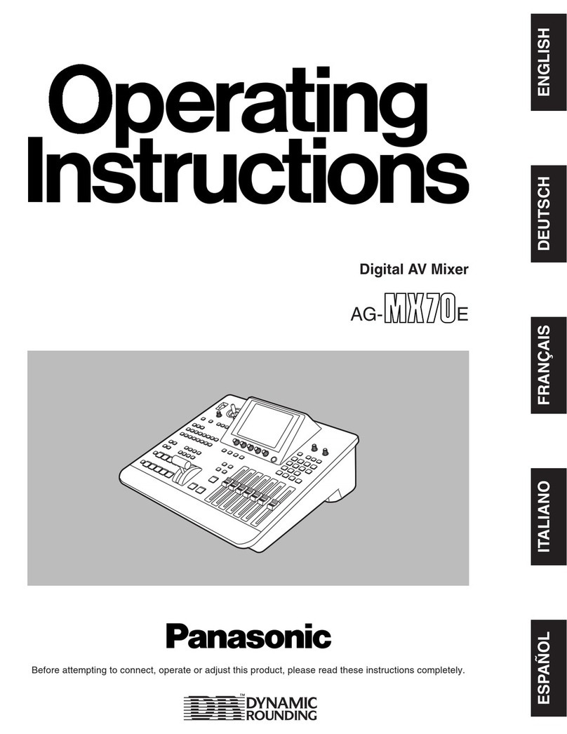
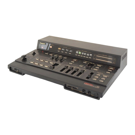
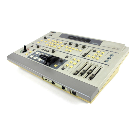
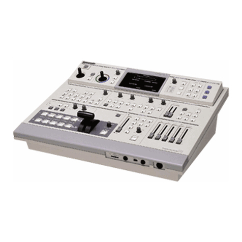
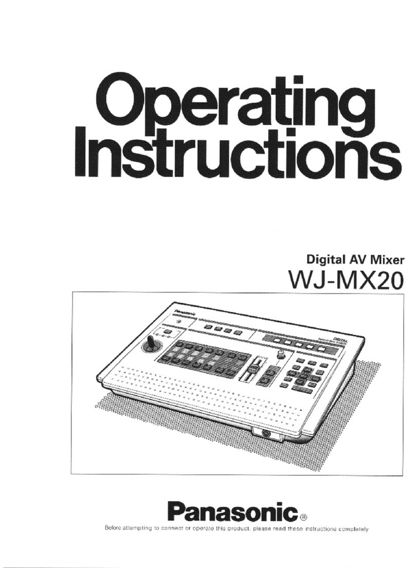
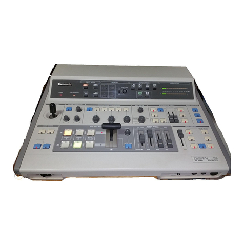
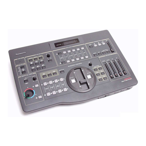
Panasonic WJMX50 - MIXER User manual

Operating
Instructions
Production Mixer
WJ-MX50
Panasonic
Before attempting to connect or operate this product, please read these instructions completely

We declare under our sole responsibility that the product to which
this declaration relates isin conformity with the standards or other
normative documents following the provisions of Directives
EEC/73/23 and EEC/89/336
i————___. __-_—_-———ForAustralia—————i
THIS APPARATUS MUST BE EARTHED.
To ensuresafe operation the three pinplug supplied must beinsert-
ed only into a standard three pin power point which is effectively
earthed through the normal household wiring Extension cords used
with the equipment must be three core and be correctly wired to pro-
vide connection to earth Wrongly wired extension cords are a major
cause of fatalities
The fact that the equipment operates satisfactorily does notimply
that the power point is earthed and that the installation is completely
safeFor your safety if in any doiibt about the effective earthing of
the power point consult a qualified electrician
The lightning flash with arrowhead sym-
bol, within an equilateral triangle, is
interned to alert the user to the presence
of uninsulated "dangerous voltage' within
the product's enclosure that may be of
sufficient magnitude to constitute a riskof
electric shock to persons
The exclamation point withinan equilat-
eral triangle is intended to alert the user
to the presence of important operating
and maintenance (servicing) instructions
in the literature accompanying the appli-
ance
The serial number of thisproductmaybefoundonthe
bottom of the unit
You should note the serial number of this unitin the
space provided and retain this book as a permanent
record of your purchase to aid identification in the event
of theft
Model
No.__________________
Serial
No.
__________________
WARNING
TO PREVENT FIRE OR SHOCK HAZARD, DONOT EXPOSE THIS APPLIANCE TO RAIN OR MOISTURE
CAUTION:
Before attempting to connect or operate this product,
please read the label on the bottom

CONTENTS
Preface 2
Features 2
Precautions 3
Major operating controlsand their functions 4
System Connection 14
Operation 17
A Pre operational Set up17
B Basic operation 1 18
C Basic operation 2 Digital Effectbloc 20
D Basic operation-3 Mix and Wipe block 22
EBasic operation-4 Downstream Key 32
F Basic operation 5 Fade33
G Basic operation-6 Audio Follow 34
H Application 35
Interface 38
Specifications 40
Standard Accessory 40
Optional Accessories.40
PREFACE
The Panasonic Production Mixer WJ MX50 is designed for
use in producing specially effected images by utilizing digital
processing circuitries like the built in Frame Synchronizer
In addition to the Mix Effectof the conventional Production
Mixer, the WJ-MX50 includes such features as Chroma Key
and Luminance Key functions Additionally this unit has
various functions such as Digital Effect, Downstream Key
Effect, Wipe Effect,Fade Control, Memory and much more
Also VTR Editing Controller can be connected for AB roll
editing purposes This operating manual is intended to
explain theGenerators many operationalfeaturesWith
the WJ MX50 and your imagination there are many possible
function combinations which are left to your creativity
MAIN FEATURES
1 Built-in Frame Synchronizers forA busand B-bus
2Four audio/video source inputs
3 Digital Effects such as Nega, Mosaic, Mono, Paint, Still,
Strobe, Multi, Trail and AV Synchro
4 Several combinations between the Chroma Key,
Luminance Key, NAM, Mix, and Wipe
5 287 Wipe-pattern combinations are available
69standard background matte colours are avilable from
the MatteGenerator
7 Audio fade, DSK fade and/or video fade are available
either independently or in combination
8 The interval time for the AutoFadeand Auto-Take can
be adjusted independently
9 The audio level can alsobelinked with movement of
the Wipe lever
10 8special effects(factory set up)included
11 8-events memory available
12 GPI and RS422/RS232C connectors for external VTR
Editing Contioller
13 Black Burst signal, Advance Sync signaland Advance
Reference signal output connectors for use with VTR
editing systems
14 Built in Demonstration modeavailable
15 Reset ON mode for returning to reset mode conditions
after power interruption
16 The mode selection of all buttons will be held
for approximately 1 week when the AC power is
disconnected as this unit has memory back up
-2-

PRECAUTIONS
The WJ-MX50isa sensitive, high quality instrument and shouldbetreated with care. And because itis an electrical device, the
danger of electric shock existsifitis used inappropriately.
xDo not attempt to disassemble the instrument. In order
to prevent electrical shock, do not remove screws or
covers. There are no user-serviceable parts inside.
xDonotabuse the instrument. Avoid striking, shaking,
etc. It could be damaged by improper handlingor
storage.
x Do not use strong or abrasive detergents when
cleaning the instrument body.
xDo not expose the instrument to water or moisture, and
do not operate itin wet or humid areas.
xDo not use the instrument in an extreme environment
where either hightemperature or high humidity exist.
•Do refer all servicing to qualified service personnel.
•Dohandle the instrument with care.
•Douse a dry cloth to clean the instrument when dirty.
In case the dirt is hard to remove, use mild detergent
and wipe gently.
•Do take immediate action if ever the instrument does
become wet. Turn the power off and referservicingto
qualified service personnel. Moisture can damage the
instrument and also create a danger of electric shock.
• Use the instrument under conditions where
temperaturesarewithin0°C-40°C, and humidity is
below 90'/.
IMPORTANT NOTICE FOR VIDEO INPUT SIGNAL
(1) If the input video signal does not meet with the PAL
colour standard, this could cause a disturbance of
synchronization. (The picture may jitter or tear)
(2) If the signal to noise ratio (S/N) of the input signal is
very low, this may bereflectedina low quality picture.
(3)Ifthesource input video signal isveryjittery, as inthe
case of a poor VIR playback signal, this could cause a
disturbance insynchronization or colour.
(4) If tracking noise is seen on the TV monitor, this could
cause a disturbancein synchronization. Itis necessary
to adjust the trackingcontrolof the input VTR.
(5) When eithera charactergenerator signal or characters
froma key camera is supplied, the edge of the
characters might become rough as shown below under
certain electronic conditions.
(6)Flag waving (top of picture curls) may appear when
certain VTR's are used as inputsignals,(due to AFC
timeconstant)
(7) When the External Key Video Signal issupplied to the
EXT. CAMERA INconnector, this signal will be used as
areference sync signal for the WJ-MX50. So if this
signal isjittery, as in the case of VTR playback signal,
this could cause a disturbance in synchronization.
-3-

MAJOR OPERATING CONTROLS AND THEIR FUNCTIONS
•TOP
VIEW
1
1. Power ON/OFF Button (OPERATE)
Press this button to turn on the power ofthe unit.
The LED on this button lights and thefollowing LEDs
lightup at the same time. C/L BAR on the Matte
Colour Indicator (11), Effect-Out Button (17), One-Way
Button (27), Straight Wipe Button (70), Effect ON/OFF
Button (59), Effect-A Button (58), Repeat Effect Button
(54), DSK-A Button (45), Matte Button (47), Wipe Select
Button (74), Source 1 on A-bus Button (102), Souce 2 on
B-Bus Button (101), Audio Follow ON/OFF Button (79)
and Black Fade Button (85). These LED's light up only
when the Reset ON/OFF Switch (109)is turned on.
Notes :
1. The Main Power Switch (in back) (131) must be on
before the Power ON/OFF Button (1) is pressed
2. When the Editing Controller AG-A800is used with
WJ-MX50, the power of AG-A800 should be off
first to turnoff the power of WJ-MX50. The power
of WJ-MX50 can notbe turned off by-itself.
3. Read Note 3 on page17.
2. Positioner Joystick
The position of the wipe pattern as selected using the
Square Wipe Button (60) can be freely set using this
Joystick control.
3. Positioner ON/OFF Button (ON)
This button must be pressed to operate the Positioner
Joystick (2).
4. Scene Grabber ON/OFF Button
(SCENE GRABBER)
The scene wiped by the Square Wipe Button (60) will
be grabbed by pressing this button. The position of this
area can then be changed by operating the Positioner
Joystick (2).
5. RGB Control
This JoystickControlpermits you to balance or change
the huefromthe images ofthe Source Video Signal
(either A or B)by moving its position When this
Controller is positioned at centre, it generates the
original colour ofthe Source Video Signal.
6. Colour - B Button (B)
Colour correction can be made on the B - bus Source
Video Signal by pressing this button. When you press it
once, theI ED starts blinking, the chroma level can be
changed by using the Chroma Level Control(8).
When you press a second time, the LEDis continuously
turned on, the huecanbe changed by using the RGB
Control (5) inadditionto the chroma level byusing the
Chroma Level Control(8).
7. Colour - A Button (A)
Colour correction can bemadeon the A - bus Source
Video Signal by pressing this button. When you press it
once, the LED starts blinking, the chroma level canbe
changed by using the Chroma Level Control(8).
When you press a second time, the LEDis continuously
turned on, the hue can be changed byusing the RGB
Control (5) in addition to the chroma levelbyusing the
Chroma Level Control (8).
8. Chroma Level Control (CHROMA)
This Controladjustst he colour level oft h e images f r o m
theSource Video Signal When this Control is set to the
centre position, it generates the original colour level of
the Source Video Signal.
Note:
Thenoise may be recorded on tape when this
control is adjusted to the MAX with excessive
colour inputsignal.
-4-

9. Audio Level Indicator (AUDIO LEVEL)
This Indicator indicates the audio output level of the
Program Out 1 Audio Output Connector (135) and the
Program Out 2 Audio Output Jacks (134)
10. Matte Colour Control (LEVEL)
The colour displayed on the Matte Colour Indicator(11)
can be adjusted with this control except C/L BAR
11. Matte Colour Indicator
The Matte Colour selected by the Matte Colour
Selectors (13) is shown by the appropriate LED
12. Graduation Button(GRADUATION)
When this button is pressed, the Matte colour of
the upper portion on the screenis less intense and
gradually increases tothatof the lower portion of the
screen
13. Matte Colour Selectors (SELECT)
Any one of 9 Matte Colours Colour Bar, White, Yellow,
Cyan, Green, Magenta, Red, Blue and Black - can
be selectedby repeatedly pressing either of these
buttons When the SELEC r () buttonis pressed,
the colour indicated on the Matte Colour Indicator
(11) changes from lower to upper. The Black will be
selectedafterthe Colour Bar. When the SELECT ( )
button is pressed, the reverse procedure takesplace.
14. Event Number Buttons (EVENT NO)
These buttons are used to memorize the present status
of all functionssettings on the unit Also thisbuttoncan
be used with the Auto Take Button (97) to recallthe
memorized status Each button has 2 memories (by
using Shift Button (18)) Upto8 memories are availabe
with these 4 buttons
Note:
Refer to the Shift Button (18) and the Memory Set
Button (19)for selection of preset memory settings
15. Program Out - A Button (A)
When thisbuttonis pressed, the A - bus source signals
which is given Effectbythe DIGITAL EFFECT function,
COLOUR CORRECTION function, SCENE GRABBER
function, COMPRESSION function or SLIDE functionis
provided at the Program Output connectors
Note:
If the MATTE on the A - busispressed, the A - bus
button will begin blinking automatically to show
you which button was selected before.
16. Program Out - B Button (B)
When thisbuttonis pressed, the B - bus source signals
whichis given Effectby the DIGITAL EFFECT function,
COLOUR CORRECTION function, SCENE GRABBER
function, COMPRESSION function or SLIDE function is
provided at the Program Output connectors
Note :
If the MATTE on the B - busis pressed, the B - bus
button will begin blinking automaticallyto show
you which button was selectedbefore
17. Effect - Out Button (EFFECT)
When this buttonis pressed, the final video signal-
whetheritiseffected or not will be provided at the
Program Output connector.
18. Shift Button (SHIFT)
This buttonwill be used when the Event Number
Buttons (14) numbered 5 to8 are required However,
in case this button is pressed with the Memory Set
Button (19) simultaneously, the unit then enters the
Special Mode (SPECIAL MODE)
Notice :
(1) Refer to page 35 for details of the Special Mode
(2)Inthe Special Mode, the LED on the Shift Button
(18) goes off and the one on the Memory Set
Button (19) startsblinking
19. Memory Set Button (MEMORY)
This button has 2 functionsIn order to activate the
Event Number Buttons (14)to memorize thecurrent
status of the unit, press the Memory Set Button
(19)prior to the Event Number Buttons (14)In
case this button is pressed withthe Shift Button
(18) simultaneously (as mentioned previously), the unit
enters the Special Mode
Notice :
(1) Refer to page 35 for details of the Special Mode
(2)In Special Mode, theLED on theShift Button (18)
goes off and the one on the Memory Set Button
(19) startsblinking
20. Multi Mode Indicator (MULTI MODE)
The number displayed on this indicator shows the mode
of the pattern by pressing the Multi Wipe Button (67)
From0 to 6 willbe indicated
21. Auto Fade Time Indicator (AUTO FADE TIME)
The number ontheindicatorshows the fading time by
picture frame when adjusting the AutoFade Transition
Control (91)
From 0 to 510 willbe indicated for every 2 frames.
22. Pattern Mode Indicator (PATTERN MODE)
The number on this indicator shows the pattern mode
which is pressed and selectedfrom the Wipe Pattern
Select Buttons number(60), (61), (62), (64), (66),(68) or
(70)
From1 to 4 willbe indicated
23 Auto Take Time Indicator (AUTO TAKE TIME)
The number on this indicator shows the Auto Take
Time bypictureframe when adjusting the Auto Take
Transition Control (98)
From0 to 510 willbe indicated for every 2 frames
24.Wipe Pattern Number Indicator (WIPE PATTERN)
The number on this indicator shows the wipe pattern
which is generatedby the combinations of the Wipe
Pattern Select Buttons number (60), (61), (62), (64), (66),
(68) or (70), and Modify Buttons number (63), (65), (67),
(69)
or
(71)
Any possible combination from 1 to 255 willbe
indicated
-
5-
•TOP VIEW 2
25. Border Button (BORDER)
This buttonis used forselectinga border wipe edge.
Pressing this button once selectsa narrow border.
Pressing this button a second time selectsa wide
border. The colour of the border is applied from the
complementary colour of selected Matte Colour.
26. SoftButton (SOFT)
This buttonis used for making the faint border wipe
edge. Pressing thisbutton once selectsa narrow soft
border. Pressing this buttona second time selects ita
wide soft border. No colour is available.
27. One - Way Button (ONE - WAY)
When this button is pressed, the wiping scenemoves
one way everytimeby changing the Mix/Wipe Lever
(99). Without using this function, the wiping scene
moves alternatelyby changing the Mix/Wipe Lever (99).
28. ReverseButton (REVERSE)
When this button is pressed, the movement of the wiped
scene will be reversed compared without pressing this
button.
29. Aspect Control (ASPECT)
The aspect ratio, used only when the Square Wipe
Button (60) is selected, canbe changed by adjusting
this control. To use this function,theAspect ON/OFF
Button (30) must beON.
Note :
The black area willbe shown along the imageon
the video monitor when the Compression function
is used withit.
30. Aspect ON/OFF Button (ON)
In case theAspect(unctionis required, this button must
firstbe pressed.
31. Negative Button (NEGA)
The on-screen image can be transposed to look likea
negative ofthe visual image by pressing this button.
32. Mosaic Size Control (SIZE)
The size ofthe pieces of the mosaic pattern can be
adjusted by twisting this control.
33. Mosaic Button(MOSAIC)
By adding small squares in mosaic-like patterns a
design or blurred image can be created. The size
of the mosaic squares can be changed byusing the
Mosaic Size Control (32).
34. Mono Colour Button (MONO)
When this buttonis pressed, the Source Video Signal
becomes a monochrome scene. This function has a
priority to the Colour Correction function in operation.
35. Paint Control (LEVEL)
The graduation of the paint effect can be changed by
adjusting this control.
36. Paint Button (PAINT)
The image canbe transformedto resemble an oil
paintingof the video scene by pressing the button.
-6-

37. StillButton (STILL)
An instant still or frozen image of the video can be
obtained by pressing thisbutton
38. StrobeButton (STROBE)
Video framescanbefrozen intermittently, to achieve
a strobe effect,by pressing this button. The strobe
interval canbe ad)usted by the Effect Interval Timer
(39) from approximately 003 seconds to2 1 seconds.
39. EffectInterval Timer (TIME)
The time of intervalfortheStrobeeffect, Multi effect
and Trail effect can beadjustedbythis timer. Also this
timer workswiththeA / VSynchrofunctionInt his case,
theA / VSynchrointerval applies totheStrobeeffect.
40. Multi Button (MULTI)
The video image on the monitor TV becomes multiple
video images by pressing this button. When you press it
first,4-imagesare displayed the second press makes
it 9-images and the third press makes it 16-images.
The fourth press returnsthe screen to a single image
screen The trailintervalcanbe changed by theEffect
Interval Timer (39) fromapproximately006 seconds to
21 seconds.
41. Trail Button(TRAIL)
The compressed video image trails one after another
from small to larger and larger video images up to
a maximum of 16images. The start position can
be selectedby the Positioner Joystick (2) either to
startfrom upper right or upper left The trail interval
can be changed by theEffect Interval Timer (39) from
approximately 006 seconds to 2 1 seconds.
42. A/V Synchro Control (LEVEL)
This controladjusts the triggersensitivity of the A/V
Synchro. When this controlis turned to the MAX
position, theA/V Synchro will be triggered by(a higher
threshold) high level sounds When this controlis turned
to theMIN position, the A/V Synchro will be triggered
by (a lower threshold) low level sounds.
43. A/V Synchro Button (A/V SYNCHRO)
Any combination of the digitaleffects (Nega, Mosaic,
Mono, Paint,Still or Strobe) canbe synchronized to
pulse with certain levels of accompanying music or
soundsupplied to the WJ-MX50.
44. DSK ON/OFF Button (ON)
This buttonis pressed to activate the Downstream Key
(DSK) effect.
45. DSK-AButton (A)
When this buttonispressed, the Source Video Signal
on the A-Bus willbe the Key-Source Signal.
46. Ext. Camera Button (EXT. CAMERA)
When this buttonis pressed, the externalcamera which
is connectedto the External Camera Input (121) or (122)
can be used as theKey-Source Signal.
47. Matte Button (MATTE)
When this button is pressed, the Matte Colour
generated inthe MATTE GENERATOR will be used
as a Key Fill Signal which istobe overlaid on the
Key-Source Signal.
48. White Button (WHITE)
When this buttonis pressed, the white colour will be
used as a Key-Fill Signal which isto be overlaid on the
Key-Source Signal.
49 Edge Button (EDGE)
This button is used to edge on the Downstream Keyed
images Two types (shadow, border) and five kinds of
edges are available by pressing this button repeatedly.
Notes :
1 When the Downstream Keyed images are white,
you can colour the edge to any one of 9 colours,
solid or graded by pressing the Graduation Button
(12) and theMatte Colour Selector (13)
2 When the Matte Coloured Downstream Keyed
images areused,the edge colour isalways black
50. Key ReverseButton(REVERSE)
The polarityof the Downstreamed Keyed Images will
be reversed by pressing this button
51. DSK-B Button (B)
When this button is pressed, the Source Video Signal
on the B-Bus will be the Key Source Signal
52. High Level Key Slide Control (KEY LEVEL)
This slide controlis used to adjust the sensitivity of the
luminancelevel of the Key signalforhigherlevel
53. Low Level Key Slide Control (KEY LEVEL)
This slidecontrolis used toadjust the sensitivity of the
luminance level of the Key signal for lower level.
54. Repeat Effect Button (REPEAT)
Each of the multiple video images will be scanned one
after another repeatedly by pressing this button.
55. Once Only Button (ONCE)
Each of the multiple video images will be scanned one
time only by pressing thisbutton It willbefrozenafter
that.
56. Frame Button (FRAME)
When this buttonis pressed the Digital Effected Image
is reproduced as a frame video image. This featureis
applied to Still, Strobe, Multi and Trail functions And
this button is used to remove the image vibration.
-7-

Note:
The difference between onandoff of this button
FRAMEBUTTON
ON
OFF
Output Signal
2-field
1-field
Resolution
Standard
Reduced
68. Corner Wipe Button
The video scene is wiped witha square shape f r o m the
corner of the monitor screen Four kinds of patterns
are available.
69. Slide Button (SLIDE)
The wiped scene slides into the monitor screen by
pressing this button once Both wiped scenes slidein
and out by pressing this button a second time.
70. Straight Wipe Button
The video scene is wiped with a straight lineFour
patterns are available.
71. Compression Button(COMPRESSION)
The compressed video scene is wiped into the monitor
screen by pressing this button once The compressed
video scenes are wiped in and out ofthe monitor
screenby pressing thisbutton a second time.
57. Effect-B Button (B)
The Source Video Signal on B-buswill receive the
Digital Effect by pressing this button(ifEffect ON/OFF
Button (59) isfirst pressed).
58. EffectA-Button(A)
The Source Video Signal on A-bus will receive the
Digital Effectby pressing this button (if Effect ON/OFF
Button ( 5 9 )isfirst pressed).
59. Effect ON/OFF Button (ON)
The selected Digital Effectfunction becomes operative
by pressing this button
60. Square Wipe Button
Four wipe patternscanbe selected by pressing this
buttonrepeatedly•circle, oval, square and diamond
The Aspect Control (29) or the Positioner Joystick (2)
can be used with these patterns.
61. Mosaic Wipe Button
The wiping becomes a mosaic-like patternbypressing
this button Four kinds of pattern are availableby
repeatedly pressing this button.
62. Split Wipe Button
The video scene is split from the centre of the image
by pressing this button Three kinds of patterns are
available by repeatedly pressing this button.
63. Blinds Wipe Button (BLINDS)
The video scene is wiped ina blinds pattern. Several
wipe combinations using buttons (62), (64), (66), (68)
and(70) are operative with this button.
64. Triangle Wipe Button
The video scene is wiped with a triangle shape.Four
patterns are available.
65. Pairing Wipe Button (PAIRING)
A paired wipe scene canbe obtained bypressing this
button. The wipe buttons of (64), (66), (68) and (70) are
operative with this button.
66. Diagonal Wipe Button
The video scene is wiped with a diagonalshape.Four
patterns are available.
67. Multi Wipe Button (MULTI)
The wiped patterncan be multipled by pressing this
button repeatedly. The effect of the multiplication
depends on the wiped pattern.
-8-

•TOP
VIEW
3
72. NAM Select Button (NAM)
NAM (Non Additive Mix) effectis obtained by pressing
this button and the Mix/Wipe Lever (99) is to be
positioned at centre The darker area on the B-bus
image and the A-bus image are replaced at relative
levelsby the lighter areas of each other, ie the
stronger (lighter) imaqe-s from either input replace the
weaker (darker) ones
73. Mix Select Button (MIX)
This buttonis pressed to obtain a Mix Effect between
the A-bus Source Video Signal and the B - bus Source
Video Signal
74. Wipe Select Button (WIPE)
This button is pressed to obtain a Wipe effect between
the A-bus Source Video Signal and the B-bus Source
Video Signal using the settings of the Wipe Pattern
Select Buttons
75. Luminance Key SelectButton( L U MKEY)
Ihe Luminance Key effectis obtained by pressing this
button and the adjustment of the Slice Control (78)The
B- bus signal must be the key signal
76. Chroma Key Select Button (CHROMA KEY)
The Chroma Key effectis obtained by pressing this
button and the adjustmentof the Hue Control (77) and
Slice Control (78) The B-bus signal must bethe Key
signal
77. Hue Control (HUE)
This controlis used to adjust the Hue of the Chroma
Key effect
78. Slice Control (SLICE)
This controlis used to adjust the slice level of the
luminance signal forthe Luminance Key effector the
chroma signal for the Chroma Key effect
79. Audio Follow Button (AUDIO FOLLOW)
When this buttonis pressed, the audio on the A-bus
and B-bus can be changed accordingtothe relative
percentage position of the Mix/Wipe Lever (99)
80. Video Fade Button(VIDEO)
When this buttonis pressed, the Wiped or Mixed video
signal will fade-in or fade-outbyusing the Fade Control
(95)
-
9-

81. Matte Fade Button (MATTE)
The video fadesignalisfaded out to the selected Matte
Colour by pressing this button.
82. DSK Fade Button (DSK)
When this buttonis pressed, the Downstream Keyed
signal will fade-in or fade-out byusing the Fade Control
(95).
83. White Fade Button (WHITE)
The video fade signal is faded out to White by pressing
thisbutton.
84. Audio Fade Button (AUDIO)
When this buttonis pressed, the audio will fade-in or
fade-out by using the FadeControl (95).
85. Black Fade Button (BLACK)
The video fade signal isfaded out to Black bypressing
this button.
86. MasterAudio Fader (MASTER)
The total audio level ofthe mixed audiosignalsis
adjusted by sliding this fader.
87. Mic/Aux-2Audio Fader (MIC/AUX2)
The audio level connectedto the Microphone Jack
(106) ortheAuxiliary Audio Input-2 Jack (136)canbe
adjusted by sliding this fader. Select the Mic or Aux-2
audio signal by the Mic/Aux-2 Switch (105).
88.Aux-1 Audio Fader (AUX1)
The audio level connected to the Auxiliary Audio Input-1
Jack (137) can be adjusted bysliding this fader.
89. B-bus Audiofader (B)
The audio level fromthe B-bus source inputs can be
adjusted by sliding this fader.
90. A-bus Audio Fader (A)
The audio level fromthe A-bus source inputs can be
adjusted bysliding this fader.
91. Auto Fade Transition Control (TRANSITION)
This controladjuststheautomatic fading time from 0 to
510 framesfor every 2 frames.
This amount is then displayed on the "Auto FadeTime
Indicator"(21).
92. Auto Fade Button (AUTO FADE)
When this button is pressed, the automatic fade
sequence forthe selected input(s) begins, withthe
time set by the AutoFade Transition Control (91) This
button remains litduring Auto-fading.
93. A-bus Fade Button (A)
The video fade signal is faded out to the A-bus video
signal by pressing this button.
94. B-bus Fade Button (B)
The video fade signal isfaded out to the B-bus video
signal by pressing this button.
95. Fade Control
The fadein and fade-out can bemanually controlled
by using this control.
96. Fade LED (IN/OUT)
When the IN (OUT) LEDis continuously turned on, the
fadeisIn (Out) situation. When theIN (OUT) LED is
blinking, the fade-in (fade-out) is currently incomplete.
97. Auto Take Button (AUTO TAKE)
The Auto Take effect- AutomaticWipe/Mix/NAMcan
be executedby pressing this button. This button lights
during the Auto-Take interval.
98. Auto Take Transition Control (TRANSITION)
The Auto Take interval time canbe adjustedby this
control from 0 to 510 framesfor every 2 frames.
99. Mix/Wipe Lever
In the wipe mode, manually movingthislever between
the A-bus and B-bus will increase the relative portion
of each bus signal, accordingto the option selectedIn
the mix mode, the audio/video are together switched
between A-bus and B-bus.
100. Mix/Wipe LED
When theA bus (or B bus) LEDis continuously turned
on, the Wipe/Mix/NAM is A-bus (or B-bus) situation.
When theAbus (or B bus) LED is blinking, the
Wipe/Mix/NAM effectis only partially completed on
the A-bus (orB-bus)side.
101. B-bus Buttons (B)
These buttons are used to select the desired
audio/video signals allocatedto the B bus input. The
Source 1/2/3/4 correspondsto the Source 1/2/3/4
audio/video inputs on the rear panel of the instrument.
102. A-bus Buttons (A)
These buttons are used to select the desired
audio/video signals allocated to the A bus input. The
Source 1/2/3/4 corresponds to the Source 1/2/3/4
audio/video
inputs on the rear
panel
o f
the instrument.
-
10
-

•FRONTV I E W
103. Headphone Level Control (LEVEL)
The audio level of the headphone can be adjusted with
this control.
104. Headphone Jack (PHONES)
Optional headphone canbe connected to this jack.
105. Mlc/Aux-2 Switch( A U X 2/MIC)
When the Mic/Aux-2 Audio Fader (87) is desired, select
either Mic or Aux-2 with this switch.
106. MicrophoneJack (MIC)
Optional microphone can be connected to this jack.
107. Title Input Connector (TITLE)
This connectoris used to connectthe optional
Character Generator WJ-KB50 (recommended)
Thepin numbers are stated below.
(1) Character IN
(2) Not used
(3) Ground
(4) Not used
(5) Sync out
(6) Not used
(7) Ground
(8) +9VOUT
(9) Ground
(10):ID
•REARV I E W
-
11
-
TITLE
Front View

108. Demo ON/OFF Switch (DEMO ON/OFF)
When this switchisinthe ON position, a
preprogrammed mixerfeaturesdemonstration takes
place.
109. Reset ON/OFF Switch (RESET ON/OFF)
In case the power of this unit isturned on while this
switchisinthe ON position, the LEDs on the panel
light up as the factory preset. In case the power of this
unitis turned on while this switchisin the OFF position,
the LEDs on the panel light up returning to how they
were (Refer to Note 3 onpage 17).
110 Sourcel COMP. Input Connector
(SOURCE1/COMP)
This connectoracceptsa 1 0 Vp-p/75 ohms composite
video signal.
111. SourcelY/C Input Connector(SOURCE1-Y/C)
This connector accepts the S Video signal
Note:
This input has a priority over that of the COMP
Connectorinthe Source 1 If theS Video signal
and the composite signal areboth supplied to the
Sourcel at the same time, only the S-Video signal
is used as a Sourcel Videosignal.
112. Source 2 COMP. Input Connector
(SOURCE2/COMP)
This connectoracceptsa 1 0 Vp-p/75 ohms composite
video signal.
113. Source 2 Y/C Input Connector (SOURCE2-Y/C)
This connector accepts the S-Video signal
Note:
Thisinputhasa priority over that of the COMP
Connector in the Source 2.If the S Video signal
and thecomposite signal are both supplied to the
Source 2 at the same time, only the S-Video signal
is used as a Source 2 Video signal.
114. Source Selection Switch
(EDIT CONTROL SOURCE SELECT, SOURCE)
This switchis used to choose between the Source
signals f o rthe Editing Controller AG A800. The relation
between thisswitch and the source selection switches
(P1.P2, AUX) on the AG-A800 is as follows.
115. Source 3 COMP Input Connector
(SOURCE3/COMP)
This connector acceptsa 1 0 Vp-p/75 ohms composite
video signal.
116 Source 3 Y/C Input Connector (SOURCE4-Y/C)
This connector acceptstheS Video signal
Note:
This input has a priority to that of COMP
Connector intheSource3.If the S-Video signal
and the composite signal are both supplied tothe
Source 3 at the same time, only the S-Video signal
is used as a Source 3 Video signal.
117. Source 4 COMP. Input Connector
(SOURCE4/COMP)
This connector accepts a 1 0Vp-p/75 ohms composite
video signal.
118. Source4 Y/C Input Connector(SOURCE3-Y/C)
This connector accepts the S-Video signal
Note:
Thisinputhasa priority tothatof COMP
Connector in the Source4.If the S Video signal
and the composite signal are both supplied to the
Source 4 at the same time, only the S-Video signal
is used a Source 4 Video signal.
119. Advance Sync Output Connectors (ADV SYNC)
In the A/B Roll Editing System, the Advance Syncsignal
fromthis connector should be supplied to the playback
VTRs which do not have the Time Base Corrector
(T B C )inside.
Note:
The enough editing accuracy may notbe obtained
withoutthis signal. This signal isnecessaryf o r the
Compression function and Trail functionwhenitis
recorded on the VTR.
120. AdvanceReference Output Connectors
(ADV
REF)
*IntheA/BRoll Editing System, the Advance Reference
Signalfrom this connector should be supplied to the
playback VTR's which have the Time Base Corrector
(T B C ) inside (or AUX video source).
Note:
The enough editing accuracy may notbeobtained
without this signal This signal is necessary for the
Compression functionand Trail function when itis
recorded on the VTR.
121. External COMP. Input Connector
(EXTCAMERA IN/COMP )
The external camera tobe used as a Key Source is
connected tothisconnector when thecamera has the
composite videosignal
122. ExternalY/C Input Connector
(EXT CAMERA IN/Y/C)
The externalcameratobe used as a Key Source is
connected to this connector when the camera hasa
S-Video Signal.
WJ MX50 SOURCE
S1-2
S2-3
S3-4
P1
Source 1
Source 2
Source 3
AG-A800
P2
Source 2
Source 3
Source 4
AUX
Source 3
Source 4
Source 1
Example:
If this switchisin the S1-2 position, Source is
selected when P1 button is pressed
-
12-

123. Program Out-1 COMP Output Connector
(PROGRAM OUT 1/COMP)
The Program Output Signal-1 of the composite video
signal is provided via thisconnector.
124. Program Out-1Y/COutput Connector
(PROGRAM OUT 1/Y/C)
The Program Output Signal-1 of the S-Video signalis
provided via this connector.
125. Program Out-2 COMP. OutputConnector
(PROGRAM OUT 2/COMP)
The Program Output Signal-2 of the composite video
signal is provided via this connector.
126. Program Out-2Y/COutput Connector
(PROGRAM OUT2/Y/C)
The Program Output Signal-2 of the S-Video signal is
provided via this connector.
127. Preview Output Connector
(PREVIEW OUT, COMP.)
The effected video of the composite video signal is
obtained at thisconnector regardless of the selection
of the Program Out Buttons (15), (16), (17).
128. Black Burst Output Connector
(BLACK BURST OUT)
The Black Burst Signal for use with system
synchronization is provided via this connectorto the
Editing Controller
129. GPI Input Connector (GPI)
In the A/B Roll Editing System, the GPI signal (General
Purpose Interface) may be used in orderto make
an interface between the WJ MX50 and the Editing
Controller
130. Cooling Fan
131. Main Power Switch (MAIN POWER)
The unit becames stand by mode by turning on this
switch. Unless this switch is turned on,the unit will not
be on even ifthe(frontpanel) Power ON/OFF Button
(1) is pressed.
Note:
The unit becomes on without pressing Power
ON/OFF Switch (1) by turning Main Power Switch
(131) on if the Reset ON/OFF Switch (109) had
been set to the OFF position. This takes place
leaving the Main Power Switch(131)offfor more
than a fewdays.
134. Program Out-2 Audio OutputJacks
(PROGRAM OUT 2/AUDIO, L/R)
The audio output signals of R channel and L-channel
on the Program Output 2 are provided via these jacks.
135. Program Out-1 Audio Output Connectors
(PROGRAM OUT 1/AUDIO L/R)
The audio output signals of R-channel and L-channel
on the Program Outputi are provided via these
XLR-connectors.
136. AuxiliaryAudio Input-2 Jacks
(AUX AUDIO IN,AUX2)
The auxiliary audioinput2 signal can be inputted
via these jacks. When the audio is supplied to the
L-channel, this audio is supplied to tlie R channel
(mono-mode) internally. When the audio is also
supplied to the R channel, this audio is used forthe
R-channel only.
137. Auxiliary Audio Input-1 Jacks
(AUX AUDIO IN,AUX1)
The auxiliary audio input1 signal can be inputted
via these jacks. When the audio is supplied tothe
L-channel, this audio is supplied to the R channel
(mono-mode) internally. When the audio is also
supplied to the R-channel,this audio is used for the
R-channel only.
138. Source 4 Audio Input Jacks
(SOURCE 4/AUDIO L/R)
Source 4 Audio Input signal canbe supplied via these
jacks When the audio is supplied totheL channel,
this audiois supplied to the R-channel (mono mode)
internally When the audio is also supplied to the
R-channel, this audio is used fortheR channel only
139. Source3 Audio Input Jacks
(SOURCE 3/AUDIO IN,AUX1)
Source 3 Audio Input signal can be supplied via these
jacks. When the audio is supplied to the L-channel, this
audio is also supplied tothe R-channel (mono mode)
internally. When the audio is also supplied to the
R-channel, this audio is used for the R-channel only.
140. Source 2 Audio Input Connectors
(SOURCE 2/AUDIO L/R)
The Source 2 Audio Input Signal can be supplied via
these XLR-connectors.
141. Sourcel Audio Input Connectors
(SOURCE 1/AUDIO L/R)
The Sourcel Audio Input Signal can besuppliedvia
these XLR-connectors.
-13-
132. Editing Control Connector
(EDITING CONTROLLER)
This connectoris used for connecting with the Editing
Controller AG-A800 or the Modem Unit.
133. RS422/RS232CSelectionSwitch
(RS422/RS232C)
When using an external product such as the Editing
Controller AG-A800 or the Modem Unit, this switchis
used to make the selection In the caseof the Editing
Controller,t u r nthisswitch to t heRS422 position In the
case of the Modem Unit, turn this switch to the RS232C
position.

SYSTEM CONNECTION
This system diagram shows the example of Panasonic A/B
ROLL
EDITING
SYSTEM
with
2
Playback
VTRs,
1
Recording
VTR and 1 Editing Controller AG-A800
For the details of operations, setting up of controls and
connections for the VTR's, refer to the corresponding
operating manuals
Playback VTR-1 Playback VTR-2
-
14-

Note
The ADV REF, ADV SYNC or BLACK BURST signal should be used.
The enough editing accuracy may not be obtained withoutthissignal.Thissignalis necessary for the Compression function and Trail
function when itis recorded on the VTR
-
15
-

-16-
The following models (or equivalents) are recommended in
this system. The S-Video signal and balanced audio signal
are also recommended to use obtaining a quality edited
outputs.
Production Mixer WJ-MX50
Character Generator WJ-KB50
External Camera WV-D510(
Playback VTR AG-7650
Recording VTR AG-7750
Editing Controller AG-A800
Monitor TV
(1) Connect the coaxial cables between the Advance
Reference Output Connectors (120) on the WJ MX50
and the REF-IN connector on both Playback VTR-1 and
-2
(2) Connect the audio cables between the Source1 Audio
Input Conector (141) /Source 2 Audio Input Connector
(140)/ProgramOut-1 Audio Output Connector (135) on
the WJ MX50 and the AUDIO OUT connector/AUDIO
IN connector on the PlaybackVTR-1/Playback
VTR-2/Recording VTR respectively.
(3) Set the Source SelectionSwitch(114) on the WJ-MX50
to the S1-2 position.
(4) Connect the control cables between the
PLAYER-1/PLAYER-2/RECORDER connectors on the
Interface UnitofAG-A800 and the REMOTE connector
on the Playback VTR-1/Playback VTR-2/Recording
VTR respectively.
(5) Connect the S-Video Cables between the Source 1
Y/C Input Connector (1 Hi/Source 2 Y/C Connector
(113)/Program Out-1Y/C Output Connector (124)
on the WJ-MX50 and the S-VIDEO OUT/S VIDEO
IN connectors on the Playback VTR-1/Playback
VTR-2/Recording VTR respectively.
(6) Connect the coaxial cable between the Black Burst
Output Connector (128) on the WJ-MX50 and the REF
IN connector on the InterfaceUnitof AG-A800
(7) Connect the control cable between the Editing Control
Connector (132) and the SW I/F connector on the
InterfaceUnitofAG-A-800
(8) Connect the control cable between the TOI/FUNIT
connector on the AG-A800and the TO KEY BOARD
connector on theInterfaceUnit of AG-A800
(9) Connect the S Video Cable between the S-Video
Output Connector on the WV-D5100 and the External
Y/C Input Connector (122) on the WJ-MX50
(10) Connect the coaxial cable between the Preview Output
Connector (127) on the WJ-MX50and the Video Input
Connector on the Monitor TV
(11) Connect the coaxial cables between the VIDEO
OUT connectors on the Playback VTR-1/Playback
VTR-2/Recording VTR and the Video Input Connectors
on the Monitor TV respectively.
(12) Connect the audio cable between the Audio Output on
the External Audio Source and the Auxiliary Audio Input
1Jacks (137) on t heWJ-MX50.

OPERATION
A. Pre-operational setup
A-1. Power
1. Turn on the MAIN POWER Switch (131) located on the
rear panel The unit is now in stand-by mode. No
operations can be executed yet.
A-2. RESET Switch
1. ON position • • • Factory preset operation mode
It is recommended t o normally keep t h e RESET Switch
(109)in the ON position. It would be helpful in case of
unexpected operational failure.
2. OFF position • • • Field Preset operation mode
The status of the operation mode will be remembered
when the power of the unitis turned off. And this
status, without Still, Strobe and Special function, is
later recalled when the power is restored.
2. Press the OPERATE Button (1) on the operation panel
The unit is now inoperation mode and the Cooling Fan
(130) located on therear panel startsto rotate. The
LED's on theoperation panel light up as shown if the
RESET Switch (109) was already in the ON position.
A-3.DEMO Switch
1. ON position
The preprogrammed demonstration of the built-in
Effectfunctions of theWJ-MX50 will beautomatically
displayed on an attached video monitor.
Note:
This feature is useful for demonstrating functions
to a new user to help familiarize him/herself with
the unit.
2. OFF position
The unit reverts to standard operation mode.This
switch is normally set to the OFFposition.
Notes:
1 If you donotuse the unit for an extended period
of time or to shut off the power completely, switch
off the MAIN POWER Switch (131).
2. If the Cooling Fan (130) does not rotate, turn off
and disconnect the AC power cord. Call service
personnel beforeattemptingfurther use.
3. The power of WJ-MX50 can be turned on from
the Stand-by mode by turning on the power of
AG-A800. In this case the LED of the Mix Select
Button (73) turns on instead of the Wipe Select
Button(74).
A-4.Confirm that the unitisin the operation mode. Then
set upthe operation panel as mentioned in the next
operating procedure.
-
17
-

B. Basic Operation-1
Note:
The A bus or B bus video signal sent out fromthe
PROGRAM OUT connecctors (123) (126) will be
effectedby the Colour Correction, Digital Effect,
Position, Downstream Key, Mix Effectand Fade
Control So do not add these effects to the video
if you want to see the original source videosignal
B-2. Matte
The Matte Colour produced by the MATTE GENERATOR
has9 colours to choose from Colour Bar (C/L BAR),
White, Yellow, Cyan, Green, Magenta, Red,Blueand
Black
2. Program Out Selection
•To select the (background) matte colour, press either
SELECT Button(13) until reachingthe desired colour
The selected colour is then indicated by the LED on the
Matte Colour Indicator(11)
•To change the chroma level of the selected matte
colour, adjusttheMatte Colour Control (10) The C/L
BAR and BLACK will not be changed Incasethe
WHITE is selected, the brightness changes from black
to white
• When the GRADUATION Button (12) ispressed, the
Matte Colour is gradated accordingly (per the Matte
Colour Control) fromthetop to the bottom
Note:
When the Matte Colour is selected by the Source
Selector, itcanbe used as an alternate source
signal forthe WIPE (74), MIX (73) and NAM (72)
functions However the Matte colour can not be
usedin the following effect operation In these
cases, the Source Video Signal on the blinking
source button instead of the Matte Colour will be
displayed on the monitor automatically
1LUM KEY (75) effect
2 CHROMA KEY (76) effect
3 DOWN STREAM KEY effect
4 FADE CONTROL effect
• The audio/video signal to besent out tothe PROGRAM
OUT-1, -2 connectors (123) (124)(125) (126) (134) and
(135) is selected by the appropriate PROGRAM OUT
Buttons ( 1 5 ) (16) (17)
•Incase the Source Video Signal from the A busis to be
sent out directly, press the PROGRAM OUT A Button
(15) (The Matte Signal will not be sent out The Source
Video whose button isblinkingis sent out instead) As
for the audio, the mixed audios of A-busFader(90),
AUX1 Fader (88) and A U X 2 Fader (87) will be sent out
•In case the Source Video Signal from the B busis to
be fed out directly, press the PROGRAM OUT B Button
(16) (The Matte Signal will notbe sent out The Source
Video whose button isblinkingis sent out instead) As
for the audio, the mixed audios of B-bus Fader (89),
AUX1 Fader (88) and AUX2 Fader (87) will be sent out
•Incasethe (operation panel processed) effected video
signal is to be sent out, press the EFFECT Button (17)
As forJhe audio, the mixed audios (allunder the Master
Audio) in the AUDIO MIX is sent out
-18-
B-1. Input/Output Selection
1. Source Selector
The audio/video signal tobe inputted for effect is
selected from the respective options on the A-busand
B-bus The selected audio will be controlled by the
AUDIO MIX forthe respective A bus/B bus audio

B-3. Audio Mixer
There are7 audio source inputs on the WJ-MX50-
the Source 1/2/3/4,2 auxiliary audio inputs (AUX1, 2)
andtheexternal microphone. Each audio levelcanbe
adjusted independently by the audio faders.
The EFFECT Button (17) must be on to have the mixed
audio outputs as combined in Audio Mix.
• When the AUX2 audio (instead ofexternal microphone)
is to be adjusted, turn the AUX-2/Mic Switch (105) on
the front panel to the AUX2position
B-4. Colour Correction
This function allows for the adjustment of colour from
the selected input source, as well as compensation
forexcessive colour Using the monochrome effect,a
single tint can be cast over on entire scene image
Notes:
1 The Colour Correction will haveno effectif the
selected source video isa Black/White signal
2 The MONO Button (34) on the DIGITAL EFFECT
should beoff
3 The same colour correction shouldbeapplied to
both the A bus and B-bus signals
•Tocorrect the A-bus signal, press the A Button (7) once.
The LEDstartsblinking.Inthiscase only the CHROMA
Control (8)performs a colour correctionfortheA bus
signal. If you press the A Button (/)a second time, the
LED is turned on The CHROMA Control (8)and the
R/G/B Control (5) are then available to make colour
correctionfor the A-bussigna.lTo eliminate the colour
correction funtion, press the A Button (7) a third time to
turn off the LED.
•To correct the B-bus signal, press the B Button (6)
once. The LED startsblinkingIn this case only the
CHROMA Control (8)performs colour correctionf o r the
B bus signal If you press the B Button (6) a second
time, the LEDis turned on The CHROMA Control(8)
and the R/G/B Control (5) are then available to make
colour correction tor the B bus signal. To eliminate the
colour correction, press the B Button (6) a third time to
turnoff the LED.
•If the CHROMA Control (8) is turned fully to the MIN
position and the position of the R/G/B Control (5) to
the centre, a Black and White video image isobtained.
When adjusting the R/G/B Control (5) f rom this position,
a mono tone (R/G/B) video image is obtained.
Note:
The Black and White video image is obtained in
another way - Press the Colour-A Button (7) or
Colour B (6) Buttontwice (The LED blinks) Turn
the CHROMA Control (8) to fully MIN position.
• The A Fader(90) adjusts the audio level of the A-bus
Source Audio Signal, the B Fader (89)adjuststhat of
the B bus The AUX1 Fader (88) or the MIC/AUX2
Pader (87) adjusts each respective audio inputsignal
accordingly.
• The MASTER Fader (86) adjusts the output audio level
of the 4 mixed input faders. Itis advisable to adjust
the average output audio level to about 0 dB as
represented on the Audio Level Indicator (9).
• When the A Button (15) on the PROGRAM OUT
is pressed, the A-bus/AUX1 /AUX2-MIC audios are
output to the Program Out Audio-1, -2 on the rear
panel.
• When the B Button (16) on the PROGRAM OUT is
pressed,t h e B
bus/AUX1/AUX2MIC audios are output
to the Program Out Audio -1, -2 on the rear panel.
• When the EFFECT Button (17) on the PROGRAM OUT
is pressed, A-bus/B bus/AUX1/AUX2MIC audios are
output of the Program Out Audio -1 ,-2 on the rear panel
-
19-
Other manuals for WJMX50 - MIXER
1
Table of contents
Other Panasonic Mixer manuals

Panasonic
Panasonic WJMX20 - DIGITAL AV MIXER User manual

Panasonic
Panasonic MK-GH1WTN User manual

Panasonic
Panasonic WJMX50 - MIXER User manual

Panasonic
Panasonic WJ-AVE7 User manual

Panasonic
Panasonic WJ-MX 12 User manual

Panasonic
Panasonic AG-MX70E User manual

Panasonic
Panasonic WJ-AVE55 User manual

Panasonic
Panasonic MX-AC400 User manual

Panasonic
Panasonic WJMX30 - MIXER User manual

Panasonic
Panasonic WJ-MX10 User manual