Vivax Metrotech vLoc3 Series User manual

vLoc3 Series
Remote Antenna
User Guide
(English Edition)
Version 1.2
P/N: 4.04.000124


Table of Contents
1. vLoc3 Remote Antenna Introduction...........................................................................1
2. Standard Operation - 512Hz to 200kHz......................................................................1
2.1 Applying the transmitter Signal............................................................................1
2.2 Identifying a cable with the remote antenna........................................................2
2.3 Enhancing the loopback method of cable identication.......................................3
3. Using the SD Signal....................................................................................................4
3.1 Performing a remote antenna SD reset...............................................................5
3.2 Identifying a cable with SD mode........................................................................6
3.3 Enhancing the loopback method of cable identication with the aid of the SD
signal..................................................................................................................6
4. Using the SIS Signal...................................................................................................6
4.1 Performing a remote antenna SIS reset.............................................................7
4.2 Identifying a cable using SiS..............................................................................8
4.3 Enhancing the loopback method of cable identication using the SIS signal........9


™
Page 1
1. vLoc3 Remote Antenna Introduction
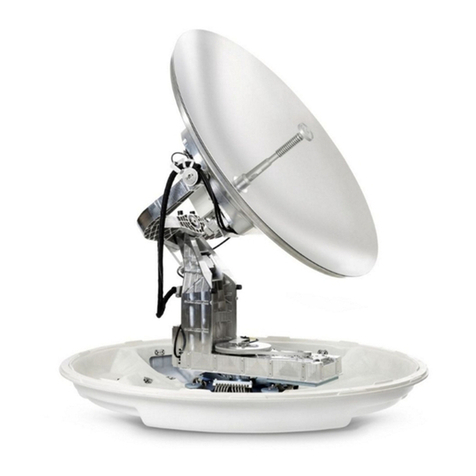
The remote stethoscope antenna can help identify a particular cable in a cable tray or
where cables are bunched together.
This user guide covers the remote antenna with the frequency range of 512Hz to
200kHz, the SD frequencies, and the SiS frequencies. The SD frequency is a receiver
option that needs to be ordered, and the SiS frequency is only available on the vLoc3-
5000 receiver and SiS transmitter.
WARNING
The remote stethoscope antenna is a useful tool to help identify
cables. However, it should not be used as identication before an
unused cable is cut. Always follow company procedures when
cutting disused or isolated cables.
The vLoc3 Series Keypad
1 2 543
6
1 On/Off button
2 Reduce sensitivity
3 Select frequency
4 Increase sensitivity
5 Enter key
6 Depth and information
2. Standard Operation - 512Hz to 200kHz
2.1 Applying the transmitter signal
Using the Transmitter Signal Clamp
The signal clamp applies a signal to the target cable and shares an equal amount with
other cross bonded cables, so although it can create multiple signals, the largest one
is most likely to be the target cable.

™
Page 2
When using the signal clamp, both ends of the target cable should be grounded. Apply
the clamp below the ground point. Applying the clamp above the ground point will
prevent the signal from nding the return path through the ground, so it is not advised.
Note: Applying the SiS or SD signals requires the use of the SiS
Signal clamp.
Using the Direct Connection Method
If it is not possible to use a signal clamp, but you can conrm that the cable is out
of service and de-energized, use the direct connection method to apply the signal.
Removing any cross bonding between cables prevents the signal from traveling along
commonly bonded cables.
A low frequency is preferred in this application because they are less likely to leak or
bleed over to other cables.
Using the Induction Method
The Induction method is least preferred because the signal will be applied on all cables
near the transmitter.
2.2 Identifying a cable with the remote antenna
1. Connect the remote stethoscope antenna to the accessory input of the receiver.
The correct settings and user interface will be automatically selected.
2. Match the frequency of the vLoc3 receiver to that of the transmitter.
3. Place the stethoscope on each of the suspected target cables. Place with the
ats of the antenna in line with the route of the cable.
NOTE

™
Page 3
59.6 512Hz120dB
4. Note the strongest signal as displayed on the bar graph in conjunction with the
dB gain setting. The strongest signal will indicate the probable target cable.
TIP
The remote antenna stethoscope can be used to help identify
disused and isolated cables. This process can be further
enhanced if the cable is isolated and is of twisted cable
construction.
WARNING
Only attempt this on disused, de-energized cables.
2.3 Enhanced "loopback" method of cable identication
1. Connect the transmitter to two of the cores of the cable. At the far end, short
together, these two conductors making a loop.
2. Set the transmitter to a low frequency such as 640Hz and set the output to
maximum.
3. At the point of interest, run the remote stethoscope antenna along the suspected
target cable. If the correct cable is being assessed, the signal will increase and
decrease in sympathy with the cables conductors twist within the cable.
4. If the signal is a steady level and does not rise and fall, this is probably not the
target cable.
TIP

™
Page 4
3. Using the SD Signal
The Remote Antenna is also capable of detecting SD signals.
1. Apply the signal using the direct connection method. Remember to isolate the
cable beforehand, as below. It is also preferable to use the ground stake as an
independent ground. Using the station ground may result in multiple signals as
the signal will return along commonly bonded cables.
2. Select an SD signal on the transmitter (either SD-USA or SD-EUR).
3. Connect the remote antenna to the vLoc3 receiver. Place it on the red lead of the
transmitter with the arrow pointing away from the transmitter. Place with the ats
of the antenna along the line of the cable.
4. Select the frequency using the "f" button to match the transmitter. The
screen should look similar to the picture below.
53.1 SD-EUR95dB
5. If necessary, adjust the sensitivity so that the bar graph is on the scale. Note that
the green arrow is pointing forward, indicates that the signal is owing forward. If
the arrow was red and pointing backward, it will be necessary to perform an SD
reset before proceeding. However, if in doubt, always perform the reset to ensure
the antenna and receiver are synchronized.

™
Page 5
49.0 SD-EUR87dB
3.1 Performing a remote antenna SD reset
Connect the transmitter to the service to be identied, place the antenna on the red
cable as previously described with the label pointing away from the transmitter.
Press the "i" button. The screen will change to something similar to the below.
0
SD
Press the "Enter" button as indicated by the "SD" icon. The screen will then
revert to the one below with an arrow pointing forward, indicating that the reset was
successful.
53.1 SD-EUR95dB
The system is now ready to identify the cable at the location of the interest.
Note that the SD reset will revert to the default setting if the
vLoc3 is switched off.
NOTE

™
Page 6
3.2 Identifying a cable with SD mode
Having conrmed that the antenna is synchronized with the receiver, proceed to the
cable's location to be identied. Place the antenna on each of the suspected cables, in
turn, ensuring the correct orientation, i.e., the arrow on the antenna pointing away from
the transmitter.
Note the signal strength on each cable and also which arrow is illuminated. The target
cable will have the strongest signal and will have the green forward arrow illuminated.
3.3 Enhancing the loopback method of cable identication with
the aid of the SD signal
As described before, a more reliable method of loop backing the signal on the cable
is possible if the cable is out of service. This method can be further enhanced with the
aid of the SD signal.
Now set up the transmitter as in the illustration below, with the far end connected and
with the transmitter connected across a twisted pair of cable. Set the transmitter to SD
EUR or SD USA and perform an SD reset as described above.
At the location of interest, hold the antenna on each of the cables in turn. Run the
antenna along the cable keeping the arrow on the antenna pointing forwards. On the
incorrect cable, the signal level will be small and steady. On the correct target cable,
the signal will rise and fall in sympathy with the cables twist. If on the target cable, at
alternate peaks, the arrows will switch from forward to backward-pointing.
4. Using the SIS Signal
The use of a Remote Antenna to help identify a cable can be further enhanced with
the use of a Signal Select Signal.
Method:
1. Apply the signal using the direct connection method. Remember to isolate the
cable beforehand, as below. It is also preferable to use the ground stake as an
independent ground. Using the station ground may result in multiple signals as
the signal will return along commonly bonded cables.

™
Page 7
2. Select an SIS signal from the transmitter (there are many available, but lower
frequencies will create less bleed off to other lines, SiS 491Hz is a good
frequency to start with).
3. Connect the remote antenna and place it on the red transmitter lead. Place it
with the arrow on the remote antenna, pointing away from the transmitter. Select
the frequency using the "f" button so that it matches the selection on the
transmitter. The screen should look similar to the below picture.
52.1
SiS844025dB
4. If necessary, adjust the sensitivity so that the bar graph is on the scale. Note that
the front half of the circle is red, indicating slight signal distortion, and the polarity
sign is "+." Indicating that the signal is owing forwards.
5. If the "-" polarity is indicated as below, it will be necessary to perform an SIS reset
before proceeding.
52.1
SiS844025dB
6. However, if in doubt, always perform the reset to ensure the antenna and receiver
are synchronized.
4.1 Performing a remote antenna SIS reset
As previously described, connect the transmitter to the service to be identied, and
place the antenna on the red cable. Press the "i" button. The screen will
change to something similar to the below.

™
Page 8
0
SD
Now press the "Enter" key. The screen should now show something similar to
the below with the "+" icon showing little or no red shown in the distortion indicator.
52.1
SiS844025dB
The system is now ready to identify the cable at the location of interest.
Note that the SiS reset will revert to the default setting if the
vLoc3 is switched off.
4.2 Identifying a cable using SiS
Having conrmed the antenna is synchronized with the receiver, proceed to the cable's
location to be identied. Place the antenna on each of the suspected cables, ensuring
the correct orientation with the ats in line with the cable and the arrow on the antenna
pointing away from the transmitter.
Note the signal strength on each cable and also which polarity is indicated. The target
cable will have the strongest signal and will have a "+" polarity.
52.1
SiS844025dB
NOTE

™
Page 9
4.3 Enhancing the loopback method of cable identification
using the SIS signal
As described before, a more reliable method of loop backing the signal on the cable
is possible if the cable is out of service. This method can be further enhanced with the
aid of the SIS signal.
Method:
Set the transmitter to a SiS frequency such as SiS 491Hz perform a SiS reset as
described above.
Now set up the transmitter as in the illustration below, with the far end connected and
with the transmitter connected across a twisted pair of cable.
At the location of interest, hold the antenna on each of the cables in turn. Run the
antenna along the cable keeping the arrow on the antenna pointing forwards. On the
incorrect cable, the signal level will be small and steady. On the correct target cable,
the signal will rise and fall in sympathy with the cables twist. Also, if on the target
cable, at each peak, the polarity indicator will also change in sympathy from "+" to "-".
Further conrmation can be achieved by the following:
• Run the antenna along the cable with the ats in line with the cable, stopping at a
positive (+) peak signal.
• Rotate the antenna around the cable keeping the antenna at the same point
along the cable.
• If on the correct cable, when directly on the opposite side of the cable, the signal
will again peak, but the polarity indicator will show "-".
SIS

™
Page 10
Vivax-Metrotech Corp. (Headquarters)
3251 Olcott Street, Santa Clara, CA 95054, USA
T/Free: 1-800-446-3392
Tel: +1-408-734-1400
Fax: +1-408-734-1415
Email: [email protected]
Website: www.vivax-metrotech.com
Visit us at www.vivax-metrotech.com to view our full product line and worldwide
locations.


Other manuals for vLoc3 Series
7
Table of contents
Popular Antenna manuals by other brands
AvL Technologies
AvL Technologies 1278K Operation and maintenance manual
ESCO Technologies
ESCO Technologies ETS Lindgren 3147 user manual

Novatel
Novatel GPS-704-WB user guide
TRENDnet
TRENDnet TEW-AI86DB Specifications

Megasat
Megasat Caravanman Kompakt 3 Twin user manual

PowerQ
PowerQ PowerHD 100 user guide
