Vivint DW02 User manual
4931 N 300 W Provo, UT 84604
Programming Instructions
•Loop 1:For when the external input option is used.
•Loop 2 (default):For when the magnet is used.
Quick Reference
T
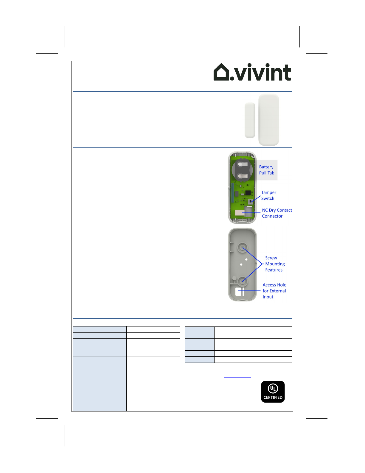
he Vivint Door and Window Sensor (DW12) is a security device that is installed
on doors, windows, and other objects in order to monitor
and report open and
closed states. The
DW12 transmits a signal to the control panel/hub when the
magnet
is moved away from, or close to, the DW12 sensor.
The DW1
2 has an external input option for NC (Normally Closed) dry contact
connections
, or it can be used with the provided magnet directly with the sensor.
The DW12 is also equipped with a cover tamper switch for additional security.
Installation Instructions
For internal switch usage
(magnet):
1. Secure the sensor to the door frame using the adhesive or screws.
NOTE: It is recommended to install the sensor on the side that will
be moving less (e.g. the frame instead of the door or window).
2. Secure the magnet adjacent to the sensor on the door or window
using the adhesive. IMPORTANT: The maximum allowable distance
between the magnet and the sensor is 0.7 in (17 mm).
NOTE: If necessary, use the provided spacer to raise the magnet so
that it aligns better with the sensor. Remove the magnet's back
using a small flathead screwdriver and replace it with the spacer.
Installer / User Test
O
pen and/or close the door or window where the DW12 is installed to ensure the sensor is transmitting
correctly to the
control panel/hub. The state change (open/closed) of the door or window should be recognized.
Door and Window Sensor
(VS-DW12-345)
PRINT INSTRUCTIONS:
REFERENCE SHEET FOR VS-DW12-345, P/N 77-600047-001 REV 1.0 |
INK: BLACK | MATERIAL:20 LBMEAD BOND | SIZE:5.50" X 8.50" SCALE 1:1 |
FOLDS: TRI-FOLD VERTICAL, TRI-FOLD HORIZONTAL (TO FIT INBOX)
For external switch usage (NC dry contact):
1. Secure the external contact switch in the desired location.
2. If necessary, drill a hole to allow the wires to reach the sensor.
3. Feed the wires through the drilled hole and then the access hole.
4. Connect the wires into the NC dry contact connector.
NOTE:With solid-core wire you should be able to push the wire
directly into the connector. Press the button to release the wire.
5. Mount the sensor in the desired location and reattach the cover.
NOTE:
Store any excess wire in the sensor.
Technical / Hardware Specifications
Vivint Part Number (P/N)
VS-DW12-345
Model Number (M/N)
DW02
Wireless Signal Range
350 ft. (106.7 m), open air
Battery
Panasonic CR2032 or
equivalent lithium battery
Battery Life
3-5 years (normal usage)
Transmitter Frequency
345 MHz
Code Outputs
Open, Close, Tamper, Low
Batt., Loss of Supervision
Supervisory Interval
70 minutes per signal (12
hours for panel/hub to
report supervision failure)
Operating Temp. Limits
32° to 120°F (0° to 49°C)
Relative Humidity
5-95% Non-Condensing
Standards Certifications & Listings
UL 634
Standard for Connectors and Switches
for Use with Burglar-Alarm Systems
ULC Subject
C634
Standard for Connectors and Switches
for Use with Burglar-Alarm Systems
FCC ID:
2AAAS-DW02
IC:
10941A-DW02
*For complete regulatory compliance
i
nformation, go to: vivint.com/fcc.

FCC and ISED Canada Regulatory Compliance Declarations*
CAUTION:
Unauthorized changes or modifications could void the user’s authority to operate the equipment.
This device has been tested and found to comply with the limits for a Class B
digital device, pursuant to Part 15 of FCC Rules and Industry
Canada license
-exempt RSS standard(s). Operation is subject to the following two conditions:
(1) This device may not cause harmful interference, and
(2) This device must accept any interference received, including interference that may cause undesired operation of the device.
These limits are designed to provide reasonable protection against harmful interference in a residential installation. This e
quipment
generates
, uses, and can radiate radio frequency energy and, if not installed and used in accordance with the instructions, may cause
harmful interference to radio communications. However, there is no guarantee that interference will not occur in a particular
installation.
If this equipment doe
s cause harmful interference to radio or television reception, which can be determined by turning the equipment off
and on, the user is encouraged to try to correct the interference by one or more of the following measures:
•Reorient or relocate the receiving antenna.
•Increase the separation between the equipment and the receiver.
•Connect the equipment into an outlet on a circuit different from that to which the receiver is connected.
•Consult the dealer or an experienced radio/television technician for help.
PRUDENCE!
Changements ou modifications pourraient annuler le droit de l'utilisateur à utiliser l'équipement non autorisées.
Conformément à la réglementation d'Industrie Canada, le présent émetteur radio peut fonctionner
avec une antenne d'un type et d'un
gain maximal (ou inférieur) approuvé pour l'émetteur par Industrie Canada. Dans le but de réduire les risques de brouillage radioélectrique
à l'intention des autres utilisateurs, il faut choisir le type d'antenne et son g
ain de sorte que la puissance isotrope rayonnée équivalente
(p.i.r.e.) ne dépasse pas l'intensité nécessaire à l'établissement d'une communication satisfaisante.
Le présent appareil est conforme aux CNR d’Industrie Canada applicables aux appareils radio exempts de licence. L’exploitatio
n est
autorisée aux deux conditions suivantes:
(1) l’appareil ne doit pas produire de brouillage, et
(2) l’utilisateur de l’appareil doit accepter tout brouillage radioélectrique subi, même si le brouillage est susceptible d’en
compromettre le fonctionnement.
Ces limites sont conçues pour fournir une protection raisonnable contre les interférences nuisibles dans une installation rés
identielle. Cet
équipement génère, utilise et peut émettre une énergie de radiofréquence et, s'il n'est pas installé et utilisé conformément
aux
instructions, il peut causer des interférences nuisibles aux communications radio. Cependant, il n'existe aucun
e garantie que des
interférences no se produiront pas dans une installation particulière. Si cet équipement provoque des interférences nuisibles
à la
réception radio ou télévision, ce qui peut être déterminé en mettant l'équipement hors et sous tension, l'
utilisateur est encouragé à
essayer de corriger l'interférence par une ou plusieurs des mesures suivantes:
•Réorienter ou déplacer l'antenne de réception.
•Augmentez la distance entre l'équipement et le récepteur.
•Connecter l'équipement à une sortie sur un circuit différent de celui sur lequel le récepteur est branché.
•Consulter le revendeur ou un technicien radio / télévision expérimenté pour de l'aide.
WARNING! The polarity of the battery must be observed (as shown in the image). Improper handling of
lithium batteries may result in heat generation, explosion, or fire, which may lead to personal injury.
Replace only with the same or equivalent battery type as recommended by the manufacturer.
AVERTISSEMENT! La polarité de la batterie doit être observée (comme indiqué dans l'image). Une
mauvaise manipulation des piles au lithium peut conduire à la production de chaleur, une explosion ou
un incendie, ce qui peut entraîner des blessures. Remplacez-le par le même type ou équivalent de la
batterie tel que recommandé par le fabricant.
Batteri
es must not be recharged, disassembled or disposed of in fire. Disposal of used batteries must be made in
accordance with the waste recovery and recycling regulations in your area. Keep away from small children. If batteries
are swallowed,
promptly see a doctor.
California Only:
Perchlorate material special handling may apply. For more information, visit:
www.dtsc.
ca.gov/hazardouswaste/perchlorate
Battery Installation
To replace
the battery, insert a coin into the top slot and gently twist until the cover releases. Use only the recommended
replacement batteries (see Specifications).
Wireless Product Notice
Wireless communications hardware provides reliable communication; however, there are limitations which must be observed.
•The transmitters are required to comply with all applicable wireless rules and regulations. As such, they have limited
transmitter power and limited range.
•Wireless signals may be blocked by radio signals that occur on or near their operating frequencies.
© 2022 Vivint Inc. All Rights Reserved. | www.vivint.com | M/N: DW02 | Doc P/N: 77-600047-001 Rev. 1.0
This manual suits for next models
1
Table of contents
Other Vivint Accessories manuals


