Vivint AirBridge VS-YOFIMN-000 User manual

Installation Instructions Outline
Installing
the AirBridge node is simple and straightforward, and can be quickly learned and mastered. As noted, you can install multiple VAB nodes to a Vivint
system
that is based on the Smart Hub control panel (SkyControl is not supported) if warranted by the home environment and size and scope of the system.
IMPORTANT:In order to configure the secure dedicated Vivint network, either the initial AirBridge node or the Smart Hub panel itself must be hardwired to
the home's broadband internet router via an Ethernet connection, designating that hardwired component as the network's single portal node. To be clear,
only one portal node is allowed on the Vivint network, and the Ethernet port on the VAB can be used for connection only when it is acting as that portal node.
The Vivint
technician should carefully read these steps in order to ensure a successful installation and optimal performance. For additional information, including
details for specific network configurations and troubleshooting guidelines, refer to the Field Service Smart Home Pros website.
Bottom View —
The
Vivint AirBridge™ wireless mesh node is a connectivity device that can be added to the homeowner's Vivint Smart
Home syste
m. This proprietary 5GHz Wi-Fi solution creates a secure mesh network dedicated to a Vivint system with
the
Smart Hub panel and connected devices such as cameras, sensors, etc. Vivint AirBridge is not supported on
the older
SkyControl panel.
Adding Airbridge node(s) to configure a dedicated Vivint network eliminates bandwidth sharing
on the
local network,
worry about rogue devices, and the need for third-party hardware such as repeaters, extenders, etc.
Y
ou can, if necessary, add more than one node to the system in order to expand coverage for the Vivint network (see
below for details
). AirBridge optimizes network traffic; increases signal strength between cameras and the panel,
enhanc
ing video quality; and improves the speed, reliability, and control of the overall Vivint smart home experience.
Vivint
AirBridge (VAB) is professionally installed by a Vivint Field Service Pro (FSP) technician. VAB nodes are added to
the
system via either NFC or WPS. Features include an LED light that indicates function and status; and a multi-function
button that lets you toggle the LED on
/off, send a WPS signal to the panel, and reboot or reset the node. Once installed
and
configured, AirBridge nodes operate seamlessly and transparently in improving every aspect of the Vivint
network/
system. In other words, when functioning properly AirBridge requires very little if any end user interaction.
This document includes a product description
overview, key features, illustrations, installation and test instructions, as
well as technical specifications
, standards certifications listings, and regulatory notices and declarations.
Vivint
AirBridge Wireless Mesh Node
(V
S-YOFIMN-000)
Quick Reference (Overview, Installation, Specs, Regulatory)
PRINT INSTRUCTIONS: REFERENCE SHEET FOR VS-YOFIMN-000, DOCUMENT P/N 77-600036-001 REV 1.0 |
INK:
BLACK | MATERIAL: 20 LB MEAD BOND | SIZE: 8.50" X 11.00" SCALE 1:1 |
FOLDS:
BI-FOLD VERTICAL, BI-FOLD HORIZONTAL (TO FIT IN BOX)
Follow these steps to pair a VAB node and add it to the system:
1. First, change the panel connection type to AirBridge mode.At the panel, tap on the menu icon (…) in the
bottom right corner > tap Software version > enter the PIN code 2203 to access the Installer Toolbox > tap
Networking > and then select AirBridge. Press Back > and then press OK to confirm the change.
IMPORTANT: Do NOT reboot the panel during the AirBridge node installation process. Once the node(s)
are installed, the network connection status will update to show the new connection type.
2. Pair the VAB node to the panel via NFC. In the Installer Toolbox > tap Networking > Add AirBridge > NFC >
and then tap Add. Align the upper left side of the VAB node with the white LED light in the bottom right
corner of the panel, and hold it in physical contact with the panel until pairing is complete (this may take
several minutes, make sure to wait until prompted that the node is successfully paired).
NOTE: If NFC doesn't work you can use WPS, making sure to first plug in the VAB node (powered on) and
then press the button on the bottom of the node for 3-5 seconds to send a WPS signal to the panel.
3. Name each VAB node that you add. In the Installer Toolbox > tap Networking > Advanced Networking >
AirBridge Node View. Tap the node and then its name field to enter a unique descriptive name (based on its
location and function as either a portal or point node).
4. Install the VAB node. Plug the node directly into an unswitched wall outlet.
NOTE: If the panel is wirelessly connected to the home router, you must install the first VAB node (as the
network's single portal node) where it can be directly connected to the router via the Ethernet port.
However, if the panel is hardwired to the router, you should install the first VAB node and subsequent
nodes (as network point nodes) in a location that best enhances network performance, such as in between
a camera with a weak signal and the panel. You can use the AirBridge Network Graph tool (on the
Networking page) to both view the network and to determine how many nodes are needed and where
they should be installed for optimal coverage. See the Field Service Pros website for details and examples.
5. Verify power is present at the node. The LED will illuminate white. (See LED descriptions.)
6. Wait for the node to establish a connection to the panel and update its firmware. The LED will illuminate
green. This may take several minutes, make sure to wait until prompted that the node is connected.
7. If after running the Network Graph tool you need to install multiple nodes, follow the same steps as above.
8. Once finished, the panel will automatically configure all of the nodes on the Vivint network.
Back View —
Front View —
Button Functionality
The button located on the bottom of the
AirBridge node can
perform multiple functions, as described below
.
•Press & let go quickly — Toggles on/off the LED light
•Press & hold for 3-5 seconds — Sends a WPS signal
•Press & hold for 10 seconds — Reboots the node
•Press & hold for 20 seconds — Factory resets the node
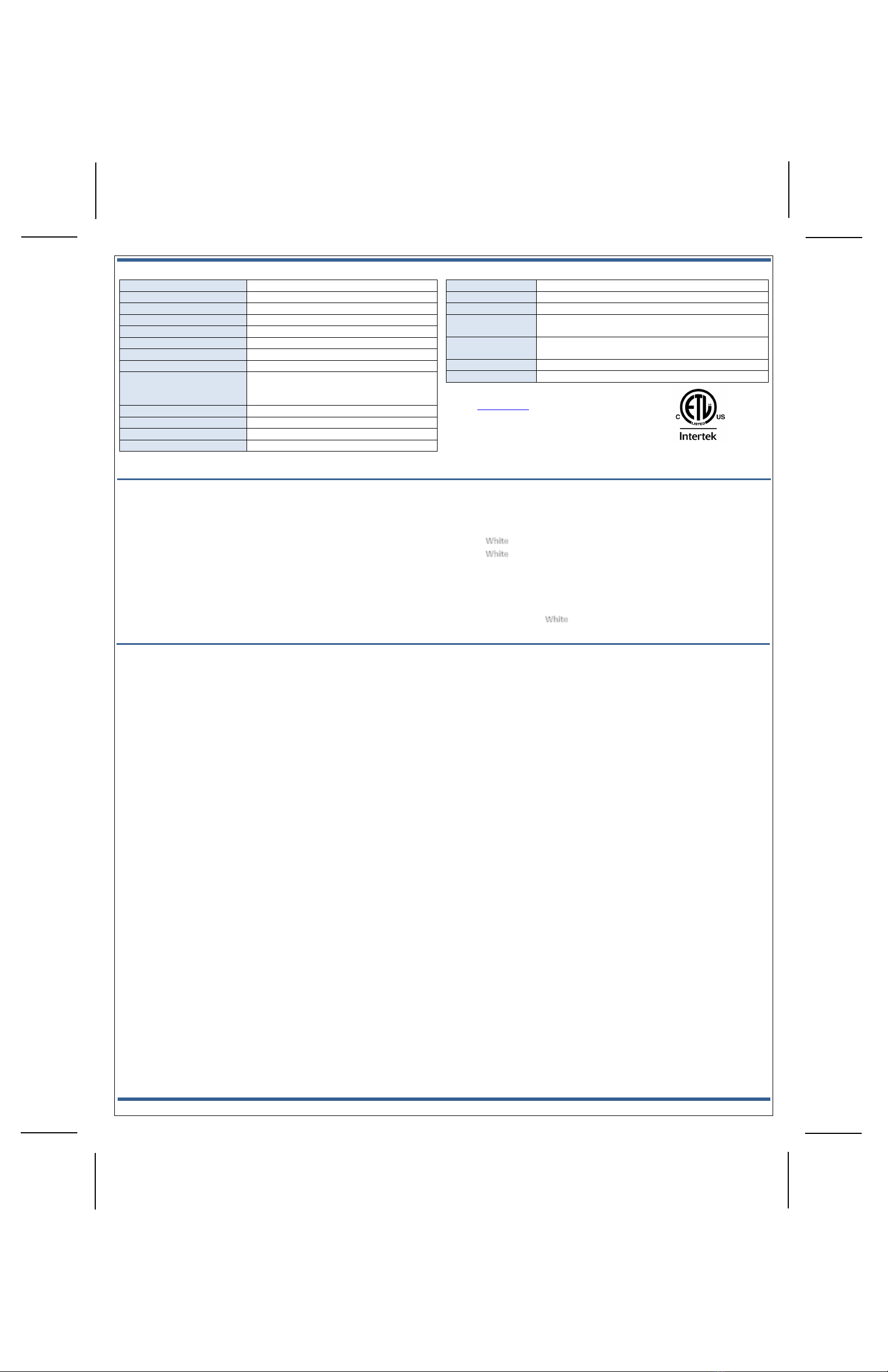
Technical
/ Hardware Specifications
Vivint Part Number (P/N)
VS-YOFIMN-000
Model Number (M/N)
BB01
Color
White
Weight
7.1 oz. (approximate)
Dimensions
4.15w x 4.15h x 1.32d cm (1.6w x 1.6h x .5d in.)
Power Usage
100-240V~ 50/60 Hz. Input 0.3A (direct plug-in)
Backup Battery
None
Wireless Signal Range
150 ft.
Connectivity (Frequency Bands,
Network Standards, Ports)
WLAN 2.4GHz (client) / 5GHz (backhaul); IEEE
802.11 a/b/g/n/ac; 2x2 MU-MIMO; NFC at 13.56
MHz; 10/100 Ethernet (non-POE) for WAN only
Communication Security
WPA2 for secure transmission
Camera Support
Maximum 6 cameras per VAB node
Operating Temperature Limits
32° to 122°F (0° to 50°C) ‡
Relative Humidity
20-85% Non-Condensing
‡
NOTE: Installation in a non-climate-controlled space with excessive ambient heat,
such
as a garage or attic, will reduce useful/service life and should be avoided if possible.
FCC and I
SED Canada Regulatory Compliance Declarations*
CAUTION!
Unauthorized changes or modifications could void the user’s authority to operate the equipment.
This device has been tested and found to comply with the limits for a Class B digital device, pursuant to Part 15 of FCC Rule
s and Industry Canada license-exempt RSS
standard(s). Operation is subject to the following two conditions:
(1) This device may not cause harmful interference, and
(2) This device must accept any interference received, including interference that may cause undesired operation of the device.
These limits are designed to provide reasonable protection against harmful interference in a residential installation. This e
quipment generates, uses, and can radiate radio
frequency energy and, if not installed and used in accordance with the instructions, may cause harmful interference to radio communications. However, there is no guarantee
that interference will not occur in a particular installation. If this equipment does cause harmful interference to radio or
television reception, which can be determined by
turning the equipment off and on, the user is encouraged to try to correct the interference by one or more of the following m
easures:
•Reorient or relocate the receiving antenna.
•Increase the separation between the equipment and the receiver.
•Connect the equipment into an outlet on a circuit different from that to which the receiver is connected.
•Consult the dealer or an experienced radio/television technician for help.
PRUDENCE!
Changements ou modifications pourraient annuler le droit de l'utilisateur à utiliser l'équipement non autorisées.
Conformément à la réglementation d'Industrie Canada, le présent émetteur radio peut fonctionner avec une antenne d'un type et
d'un gain maximal (ou inférieur) approuvé
pour l'
émetteur par Industrie Canada. Dans le but de réduire les risques de brouillage radioélectrique à l'intention des autres utilisateurs, il faut choisir le type d'antenne et
son gain de sorte que la puissance isotrope rayonnée équivalente (p.i.r.e.) ne dépas
se pas l'intensité nécessaire à l'établissement d'une communication satisfaisante.
Le présent appareil est conforme aux CNR d’Industrie Canada applicables aux appareils radio exempts de licence. L’exploitatio
n est autorisée aux deux conditions suivantes:
(1) l’appareil ne doit pas produire de brouillage, et
(2) l’utilisateur de l’appareil doit accepter tout brouillage radioélectrique subi, même si le brouillage est susceptible d’en compromettre le fonctionnement.
Ces limites sont conçues pour fournir une p
rotection raisonnable contre les interferences
nuisibles dans une installation résidentielle. Cet équipement génère, utilise et peut émettre une énergie de radiofréquence et, s'il n'est pas installé et utilisé conformément
aux instructions, il peut causer
des interférences nuisibles aux communications radio. Cependant, il n'existe aucune garantie que des interférences no se produiront pas dans
une installation particulière. Si cet équipement provoque des interférences nuisibles à la réception radio ou télé
vision, ce qui peut être déterminé en mettant l'équipement
hors et sous tension, l'utilisateur est encouragé à essayer de corriger l'interférence par une ou plusieurs des mesures suiva
ntes:
•Réorienter ou déplacer l'antenne de réception.
•Augmentez la distance entre l'équipement et le récepteur.
•Connecter l'équipement à une sortie sur un circuit différent de celui sur lequel le récepteur est branché.
•Consulter le revendeur ou un technicien radio / télévision expérimenté pour de l'aide.
© 2020 Vivint Inc. All Rights Reserved.| www.vivint.com | 1-800-216-5232 | Device M/N: BB01 | Doc P/N: 77-600036-001 Rev. 1.0
Wireless Product Notice
Wireless communications hardware provides reliable communication; however, there are some limitations which must be observed.
•The transmitters are required to comply with all applicable wireless rules and regulations. As such, they have limited transmitter power and limited range.
•
Wireless signals may be blocked by radio signals that occur on or near the wireless operating frequencies.
What the LED Light Colors Mean
The
Vivint Airbridge node features an LED light located on the front in the upper left
corner
that illuminates different colors in order to indicate various functions and
status, as described below.
•(Solid) — Powered on
•(Blinking) — Searching / pairing (press & hold for 3-5 seconds)
•Green (Solid) — Connected to the panel (successful)
•Green (Blinking) — Firmware update in progress
•Red (Solid) — Error connecting to the panel (failed)
•Red (Blinking) — Not connected to the panel / offline
•Yellow (Solid) > (Blinking) — Soft reboot (press & hold for 10 seconds)
•Yellow (Solid) > Red (Blinking) — Factory reset (press & hold for 20 seconds)
Standards Certifications & Listings
FCC
47CFR Part 15, Subpart B, Class B
ISED Canada
CAN ICES-003, Issue 6 +A1, Class B
Safety Certification
cETLus Listed
UL 62368-1
Standard for Safety for Audio/Video, Information and
Communication Technology Equipment
CSA C22.2 No. 62368-1
Standard for Safety for Audio/Video, Information and
Communication Technology Equipment
- Contains FCC ID:
2AAAS-NM01
- Contains IC:
10941A-NM01
Troubleshooting Tips
Possible failures with the
Airbridge (VAB) node and what to do in order to resolve:
•VAB node is not pairing to the panel (NFC progress stops) –
Factory reset the node, and then try again
•VAB node is not connecting to the panel –
Ensure the node is close enough to the panel (20 ft. recommended)
and does not have too many obstructions (walls, floors, etc.). Move
the node if possible, or add another VAB as a point node in between.
•Camera is not connecting to VAB node(s) –
Run the rebalance tool (Installer Toolbox > Networking > Advanced
Networking > Airbridge Node View > Rebalance AirBridge Network
Reboot the panel, then reset both the camera and the VAB node
*For complete regulatory compliance information,
go to
: vivint.com/fcc.
Table of contents
Other Vivint Network Hardware manuals

Popular Network Hardware manuals by other brands


Samsung
Samsung iPOLIS SRN-1670D datasheet

Cabletron Systems
Cabletron Systems EPIM-3PS installation guide

Lindy
Lindy Wireless LAN - 11 PCMCIA Card manual

ADC
ADC ADCP-90-216 user manual

Campbell
Campbell RTMS SYSTEMS instruction manual

Cabletron Systems
Cabletron Systems Environmental Module TM 9C300-1 user guide