Lindy Wireless LAN - 11 PCMCIA Card User manual

Wireless LAN - 11
PCMCIA Card
Manual English
Handbuch Deutsch
Manuel Français
Manuale Uso Italiano
LINDY Art. Nr. 52000 Version Europe: NOT FOR USE IN France + Spain
LINDY Art. Nr. 52002 Version Française

Index
LINDY ELECTRONICS LIMITED & LINDY-ELEKTRONIK GMBH - FIRST EDITION (APR 2001)
2
ENGLISH MANUAL ................................................................................................... 4
1. Introduction......................................................................................................................4
1.1 Network configurations................................................................................................4
2. 11Mbps Wireless PC Card and Utility Installation under Windows 95/98...................5
2.1 Package Content..........................................................................................................5
2.2 Installation under Windows 95/98................................................................................5
3. Set Up the Network..........................................................................................................5
3.1 Using Utility to Set Up an Ad-Hoc Network.................................................................5
3.2 Using Utility to set up an Infrastructure Network..........................................................6
4. Utility Information...........................................................................................................8
DEUTSCHES HANDBUCH........................................................................................ 9
1. Einleitung.........................................................................................................................9
1.1 Netzwerk-Konfigurationen .....................................................................................9
2. Die W-LAN 11 PCMCIA-Karteninstallation...............................................................10
2.1. Lieferumfang.............................................................................................................10
2.2. Installation unter Windows 95/98..............................................................................10
3. Die Netzwerkinstallation................................................................................................10
3.1 Die Verwendung des Utility-Programmes zur Einrichtung eines Ad-Hoc-Netzwerkes 11
3.2 Die Einrichtung eines Infrastruktur-Netzwerkes .........................................................12
4. Software-Informationen.................................................................................................14
MANUEL EN FRANÇAIS......................................................................................... 15
1. Introduction....................................................................................................................15
1.1 Configuration du réseau..............................................................................................15
2. Utilitaire d’installation de la carte.................................................................................16
2.1 Contenu de l’emballage.............................................................................................16
2.2 Utilitaire d’installation de la carte sous Windows 95/98..............................................16
3. Utilisation d’installation du réseau................................................................................16
3.1 Utilisation du programme de configuration pour mettre en place un réseau Ad-Hoc ...16
3.2 Utilisation du programme de configuration pour mettre en place un réseau
Infrastructure....................................................................................................................18
4. Informations concernant l’utilitaire..............................................................................19

Index
LINDY ELECTRONICS LIMITED & LINDY-ELEKTRONIK GMBH - FIRST EDITION (APR 2001)
3
MANUALE USO....................................................................................................... 21
1. Introduzione...................................................................................................................21
1.1 Configurazione Rete...................................................................................................21
2. Installazione scheda per PC 11Mbps Wireless e Utilitàsotto Windows 95/98.............22
2.1 Contenuto Confezione................................................................................................22
2.2 Installazione sotto Windows 95/98.............................................................................22
3. Installazione di Rete.......................................................................................................23
3.1 Utilizzo delle Utilitàinstallate su una Rete Ad-Hoc....................................................23
3.2 Utilizzo delle Utilitàper l’installazione su una Infrastruttura di Rete ..........................24
4. Utility delle Informazioni...............................................................................................25
APPENDIX ............................................................................................................... 26
1.Declaration of Conformity..............................................................................................26
2.Technical Specifications..................................................................................................28

English Manual
LINDY ELECTRONICS LIMITED & LINDY-ELEKTRONIK GMBH - FIRST EDITION (APR 2001)
4
English Manual
1. Introduction
The LINDY W-LAN 11 provides a fast and reliable solution for wireless network
access. It is compatible with the W-LAN-standard IEEE802.11b and 802.11. The
card is a PCMCIA Type II card (16 Bits) and will work with all standard W-LAN
wireless networks.
It is intended for use in e.g. Historical buildings where no cabled networks can be
installed; for the requirements of mobile utilisation within buildings, or to create a
general cable-free network (e.g. Internet) access within a specified environment
(university, school, hotel, etc).
In general it is possible to build up a network connection as peer to peer (Ad-Hoc)
between to computers with an installed W-LAN PCMCIA card, between access
points (which lets them act as wireless repeaters), or between access points and
clients (Infrastructure). The LINDY access point supports roaming functionality,
which allows a larger area to be covered by using more than one access point.
The range of one access point greatly depends on the conditions of the building
(shielding by concrete walls, pillars and girders from steel etc). It can be up to
45m under good conditions; in most cases the maximum range reaches 15 to
25m. Outside of buildings the range can be up to 250m without any special
antennas.
Please note that:
w
It is possible to listen in on a W-LAN network. Only if you enable
encryption is there a certain degree of security.
w
Without activated access restriction and password functionality
everybody in the area that owns an IEEE802.11b W-LAN card
could theoretically gain access to your network!
For instructions on how to activate the security functionality see the network set-
up section in this manual.
1.1 Network configurations
The card works under
Windows 95/98, NT
and 2000. Support for
other operating sys-
tems is under develop-
ment. Software, dri-
vers and firmware up-
dates are available via
download from
www.lindy.com.
The card can be
operated in ad-hoc
networks (peer to peer
communication
Infrastructure-Network
Ad-hoc Network
Wired Network
Wireless Network
AccessPoint

English Manual
LINDY ELECTRONICS LIMITED & LINDY-ELEKTRONIK GMBH - FIRST EDITION (APR 2001)
5
between computers with built-in W-LAN cards) or infrastructure networks
(together with a W-LAN access point). In an ad-hoc network the functionality of
the basic service set is available, in an infrastructure network it is the extended
service set, e.g. the connection to a cabled Network via an access point.
2. 11Mbps Wireless PC Card and Utility Installation under
Windows 95/98
2.1 Package Content
w
11Mbps Wireless PC Card x 1
w
Quick Installation Guide x 1
w
Software and Documentation CD-ROM or Floppy Diskette x 1
2.2 Installation under Windows 95/98
1.Insert the 11Mbps Wireless PC Card into the PCMCIA slot and start Windows.
Windows will auto-detect new hardware and Windows Wizard will display “New
Hardware Found”
2.Click on Next and insert the corresponding driver and software CD-ROM or
floppy into the appropriate drive. Click on Next.
3.Once the [Insert Win 95/98 CD-Rom into the appropriate drive, then click ‘OK’]
window appears, enter the path corresponding to the appropriate drives and
click OK.
4.Click Finish to complete the installation. Restart Win 95/98.
5.To install the 11Mbps Wireless PC Card Utility, insert the 11Mbps Wireless PC
Card driver and utility CD-ROM or disk once again. Open the WLU folder and
double-click the setup.exe icon.
6.Follow the on-screen instructions to complete utility installation, then double-
click on the Utility icon. The utility interface will then appear and configuration
can be made.
Note: You are advised to always disable the PC Card prior to removing the card
from the PC Card slot. This will allow the Windows operating system to log off
from the network server, disable the driver properly and disconnect power to the
PC Card slot.
3. Set Up the Network
3.1 Using Utility to Set Up an Ad-Hoc Network
If the wireless LAN has already been set up, simply plug in 11Mbps Wireless PC
Card. Otherwise, set up a wireless network by taking the following steps:
w
On the main utility interface, click on [Diagnostic tools] and then click
on [Site Survey]. This would disable wireless network links temporarily
and display channel quality on all 14 channels. Please note that the

English Manual
LINDY ELECTRONICS LIMITED & LINDY-ELEKTRONIK GMBH - FIRST EDITION (APR 2001)
6
blue bars will indicate the quality of channel. Select a good channel for
the Ad-Hoc Network.
w
Back on the main utility interface, click on [Network Configuration] and
“Configure the Adapter”window will appear. Setup procedures are as
follows:
1. ESSID denotes the assigned name for the designated wireless LAN. If
ESSID differs, then wireless clients will not communicate with each
other. Please note that by selecting [Use Non-Specified ESSID:
ANY], the PC card may connect to other wireless LANs. Therefore,
ESSID setup is highly recommended.
2. Example: Specify ESSID as : Wireless001.
Note: Once the ESSID is set on the initial 11Mbps Wireless PC Card, and
the rest of the ESSID remains as default value ANY, then the initial
11Mbps Wireless PC Card with the ESSID must be started first.
3. Select [Ad-Hoc] under ‘Network Type’, select a good channel as noted
in step 1. Select the channel under [Ad-Hoc Default Channel].
Note: Under Ad-Hoc, it would require a single, uniform channel to enable a
wireless networking group.
4. Using WEP. The default is
‘Disable’. If you require
high security in
transmission, please
select the Enable item and
select [Key List]. WEP
works in conjunction with
all of your clients.
Therefore, you must enter
the same key you have
entered for your other
clients. For example, if
you enter “MyCar”in key 1 for you PC Card, enter “MyCar”in key 1 for
all other clients. Please refer to the Infrastructure section for WEP key
input on the following page.
Note: When you use WEP to communicate with the other wireless clients,
all the wireless devices in this network must have the same encryption key.
5. Upon completing steps 1~3, click on [Modify] to save the new values.
3.2 Using Utility to set up an Infrastructure Network
w
On the main Utility interface, click on [Diagnostic Tools] and then click
on [Access Point Browser]. This would disable wireless connection

English Manual
LINDY ELECTRONICS LIMITED & LINDY-ELEKTRONIK GMBH - FIRST EDITION (APR 2001)
7
temporarily and the subsequent display would show status for all
available access points.
w
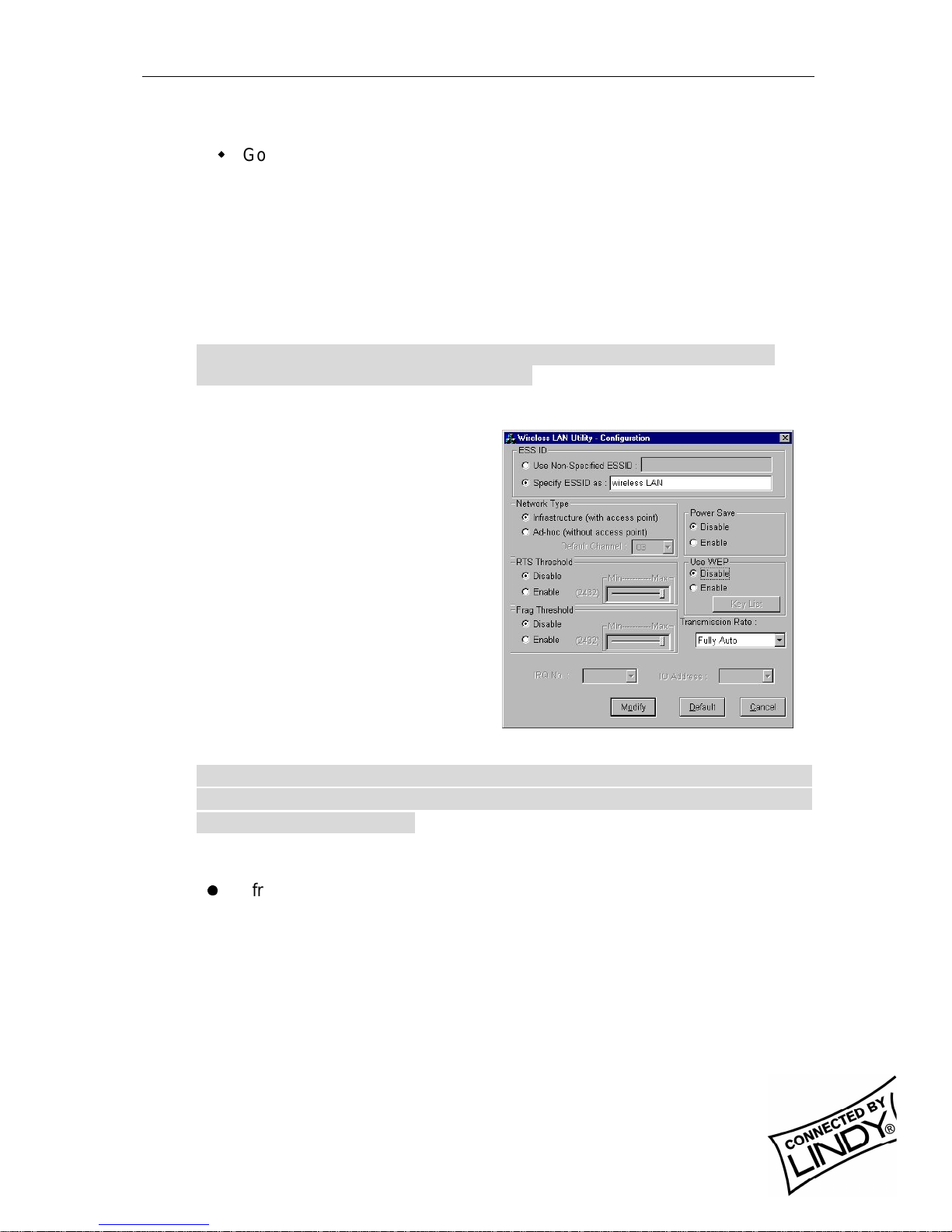
Go back to the main Utility window and click on [Network
Configuration]. Setup procedures are as follows:
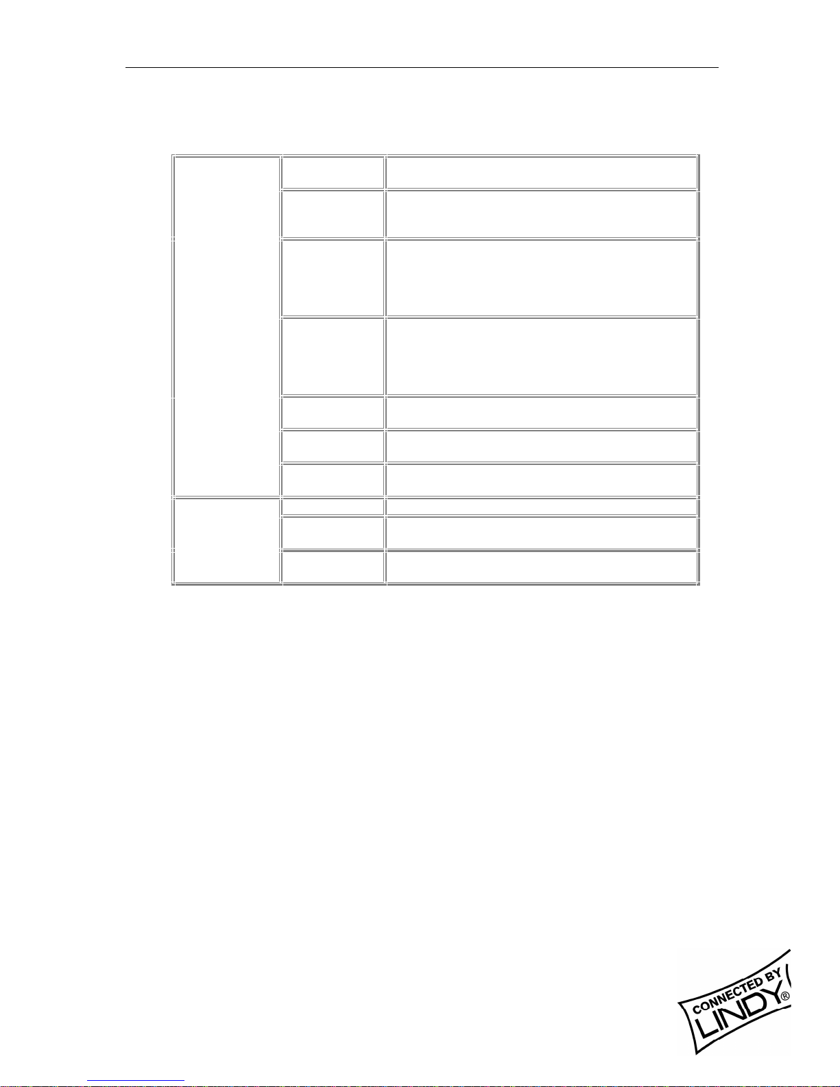
1. ESSID denotes the assigned name for the designated wireless LAN. If the
PC Card ESSID is different from the Access Point, you will not have
access to that wireless segment. Please note that by selecting [Use Non-
Specified ESSID: ANY] the PC Card could be connected to other wireless
LAN with different ESSIDs. Therefore, ESSID setup is highly
recommended.
Example: Specify ESSID as: Wireless001.
Note: If the ESSID of PC card remains as default value ANY, then the PC
card could connect to other Access Points.
2. Select [Infrastructure] under ‘Network Type’
3. Using WEP: The default is
‘Disable’. If you require high
security in transmission, please
select the “Enable”item and click
[Key List]. In the Key1 entry
field, enter ten hexadecimal digits
(any combination of 0-9, a-f, or A-
F) preceded by the characters
“0x”(E.g. 0x11aa22bb33). Or
you may enter a five
alphanumeric character in the
range of “a-z”, “A-Z”and “0-9”
(E.g. MyKey). You can repeat
this step for other 3 WEP keys if
you wish. Select a WEP key as
an active key and then click OK to make the new settings to take affect.
Note: When you use WEP to communicate with the other wireless
devices, all the wireless devices in this network must have the same
WEP Key and active key. )
4. Upon completing steps 1~3, click on [Modify] to save altered values.
l
Infrastructure network configuration provides roaming to mobile users.
Multiple (at least 2) AP connection allows wireless clients to access
seamless wireless connection while moving freely within the coverage
area. To enable Extended Service Sets (ESS), all the wireless end
devices (11Mbps Wireless PC Card, AP, etc.) must be under the same
ESSID. The wireless client will automatically connect to the nearest
Access Point.

English Manual
LINDY ELECTRONICS LIMITED & LINDY-ELEKTRONIK GMBH - FIRST EDITION (APR 2001)
8
4. Utility Information
ESSID Select the wireless network group to join
(“ANY”is default setting).
Network Type Select the station operation mode,
Ad-Hoc: (without Access Point) Infrastructure: (with
Access Point, default setting).
RTS Threshold
The threshold (number of bytes) for enabling
RTS/CTS handshake. Data with its frame size
larger than this value will perform the RTS/CTS
handshake. Value: 0~1500. For details please
refer to the 11Mbps PC Card User Manual
Fragmentation
Threshold
The threshold (number of bytes) for the
fragmentation boundary. Data will be transmitted
in fragments which its size does not exceed this
value. Value: 256~2432. (Default setting :
“Disable”)
Use WEP To have high security in data transmission.
(Default setting : “Disable”)
Power Save Power management.
(Default setting : “Disable”)
Network
Configuration
Transmission
Rate Select the transmission rate
(Default setting : “Fully Auto”)
Site Survey Inspect channel quality for your site.
Link Quality Test Inspect the point-to-point data transmission quality
between two wireless LAN stations.
Diagnostic
Tools Access Point
Browser To browse all the active Access Points in this
environment.
Software Information:
The firmware of this wireless PC card is displayed on the utility main window.
Users could download and upgrade the most recent software version from the
supplier’s web site.

Deutsches Handbuch
LINDY ELECTRONICS LIMITED & LINDY-ELEKTRONIK GMBH - FIRST EDITION (APR 2001)
9
Deutsches Handbuch
1. Einleitung
Das LINDY W-LAN 11 (Wireless LAN mit 11 Mb/s) bietet eine schnelle und
zuverlässige Lösung für kabellosen Netzwerkzugriff. Es ist kompatibel zum W-LAN
Standard IEEE802.11b und 802.11. Die Karte ist eine PCMCIA Typ II-Karte (16 Bit)
und funktioniert mit / in allen zum W-LAN Standard-konformen Funknetzwerken.
Es ist prädestiniert für den Einsatz in historischen Gebäuden, in denen keine
Kabelnetzwerke verlegt werden können, für die Anforderungen mobiler Einsatzorte
innerhalb eines Gebäudes oder um einen allgemeinen freien Netzwerkzugang (z.B.
Internet) in einer speziellen Umgebung (Universität, Hotel, etc.) zu schaffen.
Verbindungen können prinzipiell als Peer-to-Peer Verbindung (Ad-Hoc) zwischen
zwei Rechnern mit W-LAN PCMCIA Karte aufgebaut werden, zwischen Access
Points (Wireless Repeater) oder zwischen Access Point und Clients (Infrastruktur,
PCMCIA-Karte u.ä.). Der LINDY Access Point beherrscht die Roaming-Funktion, so
dass mit mehreren Access Points ein größeres Gebäude abgedeckt werden kann.
Die Reichweite ist sehr stark von den Gebäudegegebenheiten (Abschirmung durch
Wände, Träger, etc.) abhängig und kann unter günstigen Bedingungen bis 45m
reichen, im allgemeinen liegt die maximale Reichweite bei 15-25m.
Im Freien kann (ohne besondere Antennen) eine Reichweite von ca. 250m erreicht
werden.
Bitte beachten Sie, dass:
w
ein W-LAN leicht abgehört werden kann und nur mit aktivierter
Verschlüsselung (WEP) ein gewisses Maßan Sicherheit besteht !
w
ohne aktivierte Zugangsbeschränkung und ohne aktiviertes
Passwort sich jeder Nutzer mit IEEE802.11b W-LAN Karte in das
Netz einloggen kann !
Bitte beachten Sie die Aktivierungshinweise zu diesen Themen weiter hinten im
Handbuch.
1.1 Netzwerk-Konfigurationen
Die Karte funktioniert
unter Windows 95/98,
NT und 2000. Die
Unterstützung für
weitere Betriebssys-
teme ist in der Ent-
wicklung. Software,
Treiber und Firmware-
updates stehen auf
www.lindy.com zum
Download bereit.
Mit der Karte kann ein
einfaches Ad-Hoc-
Netzwerk (Peer-to-peer,
Infrastruktur-Netzwerk
Ad-hoc Netzwerk
Kabelnetzwerk
Kabelloses Netz
AccessPoint

Deutsches Handbuch
LINDY ELECTRONICS LIMITED & LINDY-ELEKTRONIK GMBH - FIRST EDITION (APR 2001)
10
Kartenkommunikation untereinander) oder ein Infrastruktur-Netzwerk (mit W-LAN
Access Point) genutzt werden.
Im Ad-Hoc-Netz stehen die Merkmale des Basic Service Set zur Verfügung.
Im Infrastruktur-Netz stehen die Merkmale des Extended Basic Service Set zur
Verfügung, z.B. die Anbindung in ein kabel-gebundenes Netz über einen Access
Point.
2. Die W-LAN 11 PCMCIA-Karteninstallation
2.1. Lieferumfang
Stellen Sie bitte sicher, dass Sie die folgenden Dinge mit der Lieferung erhalten
haben:
w
Die LINDY W-LAN 11 PCMCIA Karte
w
Dieses Handbuch
w
Die Installationsdiskette oder –CD
Sollte eines der genannten Teile fehlen, wenden Sie sich bitte an Ihren Fachhändler.
2.2. Installation unter Windows 95/98
w
Stecken Sie die PCMCIA Karte in den PCMCIA-Schacht des
ausgeschalteten Notebooks und schalten Sie das Notebook ein.
Windows wird die neue Hardware finden und den Hardware-
Installationsassistenten starten.
w
Geben Sie als Quelle für die Treiber die beiliegende CD bzw. Floppy an.
w
Klicken Sie auf Beenden um die Installation zu komplettieren.
w
Nach erfolgreichem Abschluss der Installation starten Sie bitte Ihr
Notebook neu.
w
Zur Installation der Karten-Dienstprogramme starten Sie bitte von der
beiliegenden CD oder Diskette das Programm SETUP.EXE aus dem
Verzeichnis WLU und befolgen Sie die dort gegebenen Anweisungen.
w
Starten Sie danach das Utility Programm durch Doppelklick und führen
Sie die Konfigurationseinstellungen durch.
Bitte beachten Sie: Es ist ratsam, die PCMCIA-Karte vor dem Entfernen aus dem
Slot stets zu deaktivieren. Damit ist dem Betriebssystem die Möglichkeit gegeben,
sich aus dem Netzwerk auszuloggen, die Treiber sauber zu deaktivieren und die
Stromversorgung des entsprechenden PCMCIA-Schachtes abzuschalten.
3. Die Netzwerkinstallation
Falls Sie sich ein Netzwerk mit Access Points (Infratruktur-Netzwerk) aufbauen
möchten, können Sie Abschnitt 3.1 überspringen und direkt bei Abschnitt 3.2
weiterlesen.

Deutsches Handbuch
LINDY ELECTRONICS LIMITED & LINDY-ELEKTRONIK GMBH - FIRST EDITION (APR 2001)
11
3.1 Die Verwendung des Utility-Programmes zur Einrichtung eines Ad-Hoc-
Netzwerkes
Wenn das kabellose Netzwerk bereits eingerichtet wurde, genügt es schlichtweg, die
PCMCIA-Karte in den Schacht des laufenden Notebooks zu schieben, sodann kann
eine Verbindung aufgebaut werden. Andernfalls mußdas Netzwerk mit den
folgenden Schritten eingerichtet werden:
w
Im Hauptfenster des Utility-Programmes klicken Sie bitte auf [Diagnostic
Tools], anschließend auf [Site Survey]. Dies deaktiviert kurzzeitig alle
Netzwerkverbindungen und zeigt die Signalqualität aller 14 verfügbaren
Kanäle mittels blauer Balken an. Suchen Sie einen Kanal mit guter Signal-
qualität für Ihr Ad-Hoc-Netzwerk aus.
w
Wieder im Hauptfenster des Programmes klicken Sie bitte auf [Network
Configuration]. Es erscheint nun der Hinweis: ‚Configure the Adapter’. Das
weitere Vorgehen läuft nun wie folgt ab:
1. ‚ESSID’bezeichnet den Namen des von Ihnen eingerichteten /
einzurichtenden Netzwerkes. Weicht der unter ‚ESSID’angegebene Name auf
den Clients voneinander ab, so werden diese nicht miteinander
kommunizieren. Beachten Sie bitte, daßdurch die Einstellung ‚Use Non-
Specified ESSID: non-speci’der Rechner sich mit anderen möglicherweise in
Reichweite befindlichen Funknetzwerken verbinden, und somit heilloses
Chaos in der Netzwerkzuordnung verursachen könnte. Es ist daher sehr
ratsam unter ‚ESSID’einen möglichst eindeutigen Namen zu vergeben, z.B.
<Ihr Name>.
Bitte beachten: Wenn auf nur einem System unter ‚ESSID’ein Name vergeben
und auf allen anderen Systemen die Voreinstellung ‚non-speci’beibehalten wird,
dann mußder Rechner, auf dem der Name vergeben wurde, unbedingt laufen,
damit überhaupt eine Kommunikation zustande kommen kann.
2. Wählen Sie [Ad-Hoc] unter ‚Network Type’an, und geben Sie unter ‚Default
Channel’die Nummer des Kanales ein, der bei der eingangs beschriebenen
Ermittlung der Signalqualität ausgesucht wurde. Es ist ein auf allen Rechnern
einheitlicher Kanal erforderlich, um eine Netzwerkgruppe aufzubauen.
3. ‚Use WEP’(Wireless Encryption
Protocol) sollte aktiviert werden,
wenn Ihr Netzwerk grundlegenden
Sicherheitsanforderungen bei der
Datenübertragung genügen soll.
Um einen Sicherheitsschlüssel
anzugeben, klicken Sie auf [Key
List]. Das WEP arbeitet nur, wenn
es auf allen kabellosen Clients
Ihres Netzwerkes aktiviert wird.
Daher mußauch auf allen Clients
mit dem gleichen Verschlüsselungscode gearbeitet werden, d.h. wenn

Deutsches Handbuch
LINDY ELECTRONICS LIMITED & LINDY-ELEKTRONIK GMBH - FIRST EDITION (APR 2001)
12
beispielsweise unter ‚Key1’‚MyCar’als Schlüssel eingegeben wird, muß
dieser auch auf allen anderen Clients unter ‚Key1’gleichlautend sein. Es
können entweder ein fünf Zeichen langer alphanumerischer Code (‚A-Z’, ‚a-z’
und ‚0-9’, z.B. ‚MyKey’oder ‚Alpha’) oder aber ein 10-stelliger hexadezimaler
Code (‚0-9’, ‚a-f’oder ‚A-F’) mit vorangestelltem ‚0x’(z.B. ‚0x11aabf21ce35’)
definiert werden. Es können bis zu 3 weitere Schlüssel angegeben werden.
Aktivieren Sie einen der 4 Schlüssel und klicken Sie [OK] um die Eingaben
wirksam werden zu lassen.
Bitte beachten Sie: Wenn Sie das WEP benutzen, müssen alle kabellosen
Netzwerk-Geräte, mit denen kommuniziert werden soll, den gleichen WEP-Code
und den selben Schlüssel aktiviert haben.
4. Nachdem die Schritte 1 –3 vollzogen wurden, klicken
Sie bitte auf [Modify], um die geänderten Einstellungen zu sichern.
3.2 Die Einrichtung eines Infrastruktur-Netzwerkes
w
Im Hauptfenster des Utility-Programmes klicken Sie bitte auf [Diagnostic
Tools], anschließend auf [Access Point Browser]. Dies deaktiviert kurzzeitig
alle Netzwerkverbindungen und das folgende Fenster zeigt eine Übersicht
über alle in Funkreichweite befindlichen Access Points.
w
Wieder im Hauptfenster des Programmes klicken Sie bitte auf [Network
Configuration]. Es erscheint nun der Hinweis: ‚Configure the Adapter’. Das
weitere Vorgehen läuft nun wie folgt ab:
1. ‚ESSID’bezeichnet den Namen
des von Ihnen eingerich-
teten/einzurichtenden
Netzwerkes. Weicht der unter
‚ESSID’angegebene Name von
dem des Access Point ab, so
kann keine Kommunikation
zustande kommen. Beachten Sie
bitte, daßdurch die Einstellung
‚Use Non-Specified ESSID: non-
speci’der Rechner sich mit
anderen möglicherweise in
Reichweite befindlichen
Funknetzwerken verbinden, und
somit heilloses Chaos in der
Netzwerkzuordnung verursachen
könnte. Es ist daher sehr ratsam unter ‚ESSID’einen möglichst
eindeutigen Namen zu vergeben, z.B. <Ihr Name>.
Bitte beachten: Wenn auf der Karte unter ‚ESSID’die Voreinstellung ‚ANY’
beibehalten wird, dann kann der Rechner auch mit anderen eventuell
vorhandenen Netzwerken kommunizieren.
2. Markieren Sie [Infrastructure] unter ‚Network Type’

Deutsches Handbuch
LINDY ELECTRONICS LIMITED & LINDY-ELEKTRONIK GMBH - FIRST EDITION (APR 2001)
13
3. ‚Use WEP’(Wireless Encryption Protocol) sollte aktiviert werden, wenn Ihr
Netzwerk grundlegenden Sicherheitsanforderungen bei der Datenüber-
tragung genügen soll. Um einen Sicherheitsschlüssel anzu-geben, klicken
Sie auf [Key List]. Das WEP arbeitet nur, wenn es auf allen kabellosen
Clients und Access Points Ihres Netzwerkes aktiviert wird. Daher muß
auch auf allen Clients und Access Points mit dem gleichen
Verschlüsselungscode gearbeitet werden, d.h. wenn beispielsweise unter
‚Key1’‚MyCar’als Schlüssel eingegeben wird, mußdieser auch auf allen
anderen Clients und Access Points unter ‚Key1’gleichlautend sein. Es
können entweder ein fünf Zeichen langer alphanumerischer Code (‚A-Z’,
‚a-z’und ‚0-9’, z.B. ‚MyKey’oder ‚Alpha’) oder aber ein 10-stelliger
hexadezimaler Code (‚0-9’, ‚a-f’oder ‚A-F’) mit vorangestelltem ‚0x’(z.B.
‚0x11aabf21ce35’) definiert werden. Es können bis zu 3 weitere Schlüssel
angegeben werden. Aktivieren Sie einen der 4 Schlüssel und klicken Sie
[OK] um die Eingaben wirksam werden zu lassen.
Bitte beachten Sie: Wenn Sie das WEP benutzen, müssen alle kabellosen
Netzwerk-Geräte, mit denen kommuniziert werden soll den gleichen WEP-Code
und den selben Schlüssel aktiviert haben.
4. Nachdem die Schritte 1 –3 vollzogen wurden, klicken Sie bitte [Modify]
um die geänderten Einstellungen zu sichern.
w
Die Konfiguration als Infrastruktur-Netzwerk erlaubt den Anwendern sog.
Roaming. Ein Netzwerk aus mehreren (mindestens 2) Access Points gestattet
freie und übergangslose Mobilität zwischen den Funkabdeckungsbereichen
der einzelnen Aceess Points. Um sog. Extended Service Sets (ESS) zu
aktivieren, Access Points, die nur die Aufgabe haben, den Funkabdeckungs-
bereich zu erweitern, müssen alle kabellosen Endgeräte (kabellose Clients,
Access Points etc.) unter der selben ESSID laufen. Der kabellose Client
verbindet sich automatisch mit dem Access Point, zu dem die qualitativ beste
Funkverbindung besteht. Weitergehende Informationen finden Sie auf
www.lindy.de in der Rubrik ‚Tips & More’

Deutsches Handbuch
LINDY ELECTRONICS LIMITED & LINDY-ELEKTRONIK GMBH - FIRST EDITION (APR 2001)
14
4. Software-Informationen
ESSID Wählt die kabellose Netzwerkgruppe aus, der
der Client angehören soll. (Werkseinstellung:
‚ANY’)
Network Type
Wählt den Arbeitsmodus aus: Ad-Hoc: ohne
Access Point,
Infrastructure: mit Access Point
(Werkseinstellung)
RTS Threshold
Schwellenwert (Anzahl Bytes), für die
Aktivierung des RTS/CTS Hardware-
Handshake. Daten-Frames, die größer sind
als dieser Wert, werden per RTS/CTS-
Handshake übermittelt. Wertebereich: 0 –
1500 (Werkseinstellung: ‚Disable’)
Fragmentation
Threshold
Schwellenwert (Anzahl Bytes) für die
Fragmentierungsgrenze. Die Daten werden
in Bruchstücken übermittelt, die die Größe
dieses Wertes nicht überschreiten.
Wertebereich: 256 –2432
(Werkseinstellung: ‚Disable’)
Use WEP Für Abhörsicherheit bei der
Datenübertragung. (Werkseinstellung:
‚Disable’)
Power Save Power-Management (Werkseinstellung:
‘Disable’)
Network Configuration
Transmission Rate Wählt die Datenübertragungsrate aus.
Werkseinstellung: ’Fully Auto’
Site Survey Ermittelt die Signalqualität der einzelnen
Kanäle für Ihren Standort.
Link Quality Test Ermittelt die Qualität der Datenübertragung
zwischen zwei kabellosen Stationen.
Diagnostic Tools
Acces Point Browser Ermittelt alle aktivierten und verfügbaren
Access Points der örtlichen Umgebung.

Manuel en Français
LINDY ELECTRONICS LIMITED & LINDY-ELEKTRONIK GMBH - FIRST EDITION (APR 2001)
15
Manuel en Français
1. Introduction
Le LINDY W-LAN 11 vous propose une solution rapide et fiable pour une
installation de réseau sans fil. Il est compatible avec le standard W-LAN
IEEE802.11b et 802.11. La carte d’accès est une carte PCMCIA Type II (16 Bits)
et fonctionnera avec tous les systèmes réseaux sans fil standards.
Il sera souvent utilisédans les bâtiments assez anciens ou il est impossible
d’installer une structure de câblages réseaux et pour éviter les câbles trop
visibles, ou pour installer un réseau général sans fil (ex. Internet) avec accès
dans un environnement spécifique (université, école, hotel, etc).
En général il est possible d’installer une connexion réseau par paire (Ad-Hoc)
entre les ordinateurs par les cartes W-LAN PCMCIA, entre les points d’accès
(qui les laissent agir en tant que répéteurs), ou entre les points d’accès et les
clients (Infrastructure). Le point d’accès LINDY supporte la fonction de balayage,
qui autorise une plus grande surface d’émission en utilisant plus d’un point
d’accès. La portée d’un point d’accès dépend grandement des conditions et de la
structure du bâtiment (blindage des murs, épaisseurs, poteaux en acier etc).
Il est possible d’aller jusqu’à une portée de 45m sous de bonnes conditions;
Dans la plupart des cas on obtient des portées de 15 à25m.
A l’extérieur des bâtiments, la portée peux être de 250m sans antennes spéciales
Veuillez notez que:
w
Il est possible de se connecter en toute libertésur un réseau sans
fil W-LAN. Il est seulement possible d’avoir un certain niveau de
sécuritéen activant l’option de cryptage.
w
Sans l’activation de cette option, toute personne disposant d’une
carte IEEE802.11b W-LAN pourra en théorie accéder au réseau
sans fil installé!
Pour plus d’informations sur l’activation de la sécurité, consultez la section de
configuration du réseau dans ce manuel.
1.1 Configuration du
réseau
La carte fonctionne
sous Windows 95/98,
NT et 2000. Le
support pour d’autres
systèmes d’exploita-
tion est en cours de
développe-ment. Les
logiciels, pilotes et
mises àjour de BIOS
sont disponibles en
téléchargement sur www.lindy.com.
Réseau Infrastructure
Réseau Ad-hoc
Réseau câblé
Rèseau sans fil
Point d’accès

Manuel en Français
LINDY ELECTRONICS LIMITED & LINDY-ELEKTRONIK GMBH - FIRST EDITION (APR 2001)
16
La carte peut être utilisée dans un réseau ad-hoc (par communications paires par
paires avec cartes W-LAN) ou Infrastrucures réseaux (cartes W-LAN avec point
d’accès).
Dans un réseau ad-hoc, les fonctions basiques sont disponibles, dans une
Infrastructure réseau, vous pouvez accéder aux fonctions avancées,
Par exemple la connexion d’un réseau câblépar un point d’accès.
2. Utilitaire d’installation de la carte
2.1 Contenu de l’emballage
w
Carte PCMCIA 11Mbps Wireless x 1
w
Guide d’installation rapide x 1
w
Logiciels et documentations sur le CD-ROM ou la disquette x 1
2.2 Utilitaire d’installation de la carte sous Windows 95/98
Insérez la carte PCMCIA 11Mbps Wireless dans un slot PCMCIA et lancez
Windows. Windows va détecter automatiquement le nouveau matériel et
Windows affichera “Nouveau matériel détecté”
Cliquez sur suivant et insérez la disquette de pilote correspondante dans votre
lecteur .
Cliquez sur Suivant.
Lorsque le terme [Insérez le CD-ROM Win 95/98 dans votre lecteur, et cliquez
‘OK’] apparaît, entrez le chemin correspondant au lecteur puis validez par OK.
Cliquez Terminer pour compléter l’installation. Redémarrez Win 95/98.
Pour installer les utilitaires 11Mbps Wireless PC Card Utility, insérez le CD-Rom
d’utilitaires fourni, allez dans le répertoire WLU et double-cliquez sur le
programme setup.exe.
Suivez les instructions àl’écran pour compléter l’installation, et double-cliquez sur
l’îcone Utility. L’interface de l’utilitaire va ensuite apparaître.
Note: Il est vivement recommandéde désactiver la carte PCMCIA avant de la
retirer de son slot. Cela permettra au système d’exploitation Windows de se
déconnecter du serveur réseau, désactiver correctement les pilotes et couper
l’alimentation du slot PCMCIA.
3. Utilisation d’installation du réseau
3.1 Utilisation du programme de configuration pour mettre en place un réseau
Ad-Hoc
Si le réseau sans fil a déjàétéconfiguré, connectez simplement les cartes
PCMCIA dans leurs emplacements. Dans le cas contraire, préparez un réseau
sans fil comme suit:

Manuel en Français
LINDY ELECTRONICS LIMITED & LINDY-ELEKTRONIK GMBH - FIRST EDITION (APR 2001)
17
w
Sur l’interface principale de l’utilitaire, cliquez sur [Diagnostic tools] et cliquez
sur [Site Survey]. Ceci désactivera temporairement le réseau sans fil
et affichera la qualitéde transmission sur chacun des 14 canaux. Veuillez
remarquer que les barres bleues représente la qualitéde transmission d’un
canal. Sélectionner un bon canal pour le réseau Ad-Hoc.
w
De retour sur l’interface principale de l’utilitaire, cliquez sur [Network
Configuration] et la fenêtre “Configure the Adapter”va apparaître. Les
procédures de configuration se présentent comme suit:
1.ESSID dénote le nom
assignépour le réseau
sans fil. Si l’ESSID diffère,
alors les clients ne
communiqueront pas entre
eux. Veuillez noter qu’en
sélectionnant [Use Non-
Specified ESSID: ANY], la
carte PCMCIA pourra se
connecter àd’autres
réseaux sans fil. C’est
pour cela que la
configuration des ESSID
est fortement recommandée. Exemple: Spécifiez ESSID en tant que : <Votre
Nom>.
Note: Dès lors que l’ESSID est réglésur la carte PCMCIA 11Mbps Wireless, et le
reste des ESSID sont réglés par défaut ANY, alors la carte PCMCIA 11Mbps
Wireless doit être lancée en premier.
2. Sélectionnez [Ad-Hoc] sous ‘Network Type’, sélectionnez un bon canal.
Sélectionnez ensuite le canal sous [Ad-Hoc Default Channel].
Note: Sous Ad-Hoc, il est nécessaire d’avoir un seul et uniforme canal
pour établir et mettre en place un réseau sans fil.
3. Utilisez le WEP. Le réglage par défaut est ‘Disable’. Si vous souhaitez une
haute sécuritédans les transmissions, veuillez sélectionner l’option Enable
et sélectionnez [Key List]. Le WEP fonctionne avec tous vos clients en
simultané. Cependant, vous devez entrer la même cléentrée pour les autres
clients. Pour exemple, si vous entrez “MyCar”pour la clé1 pour votre carte
PCMCIA, entrez “MyCar”pour la clé1 pour tous les autres clients. Veuillez
vous référer àla page suivante pour la gestion des clés dans les
infrastructures WEP.
Note: Lorsque vous utilisez le WEP pour communiquer avec les autres clients,
tous les périphériques wireless connectés doivent avoir la même cléde
cryptage.

Manuel en Français
LINDY ELECTRONICS LIMITED & LINDY-ELEKTRONIK GMBH - FIRST EDITION (APR 2001)
18
4.Lorsque vous aurez terminéles étapes 1 à3, cliquez sur [Modify] pour
sauvegarder les nouvelles valeurs.
3.2 Utilisation du programme de configuration pour mettre en place un réseau
Infrastructure
w
Sur la page principale de l’utilitaire, cliquez sur [Diagnostic Tools] et cliquez sur
[Access Point Browser]. Ceci désactivera temporairement les communications
sans fil et l’utilitaire vous affichera les points d’accès disponibles.
w
Revenez sur la page principale de l’utilitaire et cliquez sur [Network
Configuration]. La configuration se met en place comme suit:
1. l’ESSID prend en compte le nom
donnéau réseau sans fil. Si l’ESSID
de la carte PCMCIA est différent de
celui du point d’accès, vous n’aurez
pas accès àce dernier. Veuillez
noter qu’en sélectionnant [Use Non-
Specified ESSID: ANY] la carte
PCMCIA pourra être connectéà
d’autres points d’accès en ayant un
ESSID différent. Cependant, le
réglage des ESSID est fortement
recommandé. Exemple: Spécifiez
ESSID en tant que: <Votre Nom>.
Note: Si l’ESSID de la carte PCMCIA
est réglée par défaut ANY, la carte
PCMCIA pourra être connectée sur tous
les réseaux sans fil existants.
2. Sélectionnez [Infrastructure] sous ‘Network Type’
3. Utilisation du WEP: Le réglage par défaut est ‘Disable’. S’il est nécessaire de
posséder une haute sécuritédans les transmissions, veuillez sélectionner la
fonction “Enable”et cliquer [Key List]. Dans le champ Key1 , entrez 10 nombres
hexadécimal (combinaison 0-9, a-f, ou A-F) précédés par les caractères “0x”(Ex..
0x11aa22bb33). Ou vous pouvez également entrer un caractère alphanumérique
de l’ordre de “a-z”, “A-Z”and “0-9”(Ex. MyKey). Vous pouvez répéter cette étape
pour les trois autres clefs WEP si vous le souhaitez. Sélectionnez un WEP en
tant que clef active et validez par OK pour que les changements prennent effet.
Note: Lorsque vous utilisez le protocole WEP pour communiquer avec les autres
périphériques sans fil, ces derniers doivent avoir la même clef WEP et clef active.

Manuel en Français
LINDY ELECTRONICS LIMITED & LINDY-ELEKTRONIK GMBH - FIRST EDITION (APR 2001)
19
4. Lorsque vous aurez terminéavec les étapes 1 à3, cliquez sur [Modify] pour
sauvegarder les valeurs modifiées.
w
La configuration en Infrastructure réseau permet une facilitéde connexion pour
les utilisateurs mobiles. Des connexions AP multiples (Min. 2) permet aux
utilisateurs mobiles d’utiliser leurs périphériques sans fil tout en se déplaçant
dans la zone d’émission. Pour activer le kit d’extension (ESS), tous les
périphériques sans fil (Carte PCMCIA 11Mbps Wireless, Points d’accès, etc.)
doivent avoir le même ESSID. Le client concernése connectera
automatiquement au point d’accès le plus proche.
4. Informations concernant l’utilitaire
Network ConfigurationESSIDSélectionne le réseau sans fil àrejoindre (“ANY”est le
réglage par défaut).Network TypeSélectionne le mode opératoire de la station , Ad-
Hoc: (sans point d’accès) Infrastructure: (avec point d’accès, par défaut).RTS
ThresholdIndique le nombre d’octets pour activer RTS/CTS handshake. Les données
avec une largeur de page supérieure àcette valeur va effectuer le RTS/CTS
handshake. Value: 0~1500. Fragmentation Threshold Indique le nombre d’octets
pour la valeur fragmentation boundary. Les données vont être transmises en
fragments dont la taille ne doit pas excéder la valeur donnée. Valeur: 256~2432.
(réglage par défaut : “Disable”)Use WEPPossibilitéd’avoir une haute sécuritéau
niveau du transfert de données. (réglage par défaut : “Disable”)Power
SaveEconomie d’énergie. (réglage par défaut : “Disable”)Transmission RateSélection
du taux de transfert (réglage par défaut : “Fully Auto”)Diagnostic ToolsSite
SurveyInspection de la qualitédu canal de votre site.Link Quality TestInspection de
la qualitéde la transmission point-to-point entre deux stations wireless LAN.Access
Point Browser. Pour parcourir tous les points d’accès dans l’environnement actif.

Manuel en Français
LINDY ELECTRONICS LIMITED & LINDY-ELEKTRONIK GMBH - FIRST EDITION (APR 2001)
20
ESSID Sélectionne le réseau sans fil àrejoindre (“ANY”est le
réglage par défaut).
Network Type Sélectionne le mode opératoire de la station , Ad-Hoc:
(sans point d’accès)
Infrastructure: (avec point d’accès, par défaut).
RTS Threshold
Indique le nombre d’octets pour activer RTS/CTS
handshake. Les données avec une largeur de page
supérieure àcette valeur va effectuer le RTS/CTS
handshake.
Value: 0~1500
Fragmentation
Threshold
Indique le nombre d’octets pour la valeur fragmentation
boundary. Les données vont être transmises en
fragments dont la taille ne doit pas excéder la valeur
donnée.
Valeur: 256~2432.
(réglage par défaut : “Disable”)
Use WEP Possibilitéd’avoir une haute sécuritéau niveau du
transfert de données.
(réglage par défaut : “Disable”)
Power Save Economie d’énergie.
(réglage par défaut : “Disable”)
Network
Configuration
Transmission Rate Sélection du taux de transfert
(réglage par défaut : “Fully Auto”)
Site Survey Inspection de la qualitédu canal de votre site.
Link Quality Test Inspection de la qualitéde la transmission point-to-point
entre deux stations
wireless LAN.
Diagnostic Tools
Access Point
Browser Pour parcourir tous les points d’accès dans
l’environnement actif.
Installation et mise àjour logicielle:
La version du BIOS de la carte PCMCIA sans fil est affichée sur page principale de
l’utilitaire de configuration. Les utilisateurs pourront télécharger et mettre àjour la version la
plus récente du logiciel pour le réseau sans fil.
This manual suits for next models
1
Table of contents
Languages:
Other Lindy Network Hardware manuals