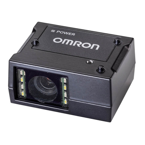
I-10 Motor Protection Circuit Breaker J7MN
Descriptions
Releases
Circuit-breakers J7MN are equipped with bimetallic-based, inverse-
time delayed overload releases and with instantaneous overcurrent
releases (electromagnetic short-circuit releases). The overload
releases can be set in accordance with the load current. The over-
current releases are permanently set to a value 13 times the rated
current and thus enable trouble-free start-up of motors. The scale
cover can be sealed to prevent unauthorized adjustments to the set
current.
Operating mechanisms
Circuit-breakers J7MN-3P are actuated via a rocker operating mech-
anism and circuit-breakers J7MN-3R, J7MN-6R and J7MN-9R via a
rotary operating mechanism. An electrical signal can be output, at all
Circuit-breakers, via a signalling switch to indicate that the Circuit-
breaker has tripped. All operating mechanisms can be locked in the
0 position with a padlock (shackle diameter 3.5 to 4.5 mm). The
J7MN Circuit-breakers fulfil the isolation characteristics specified in
IEC 60947-2.
Operating conditions
Circuit-breakers J7MN are suitable for use in any climate. They are
designed for operation in enclosed rooms under normal conditions
(e. g. no dust, corrosive vapours or harmful gases). Suitable enclo-
sures must be provided for installation in dusty or damp rooms. Cir-
cuit-breakers J7MN can also be fed from below. In order to prevent
premature tripping due to phase failure sensitivity, the three conduct-
ing paths must always be uniformly loaded. The conducting paths
must be connected in series in the case of single-phase loads.
Short-circuit protection
The short-circuit releases of J7MN circuit-breakers disconnect the
faulty load feeder from the system in the event of a short circuit and
thus prevent any further damage from being caused. Circuit-break-
ers with a short-circuit breaking capacity of 50 kA or 100 kA at a volt-
age of 400 V AC are practically short-circuit-proof at this voltage, as
higher short-circuit currents are not usually encountered at the instal-
lation point. Back-up fuses are only necessary if the short-circuit cur-
rent at the installation point exceeds the rated ultimate short-circuit
breaking capacity of the circuit-breakers.
Motor protection
The tripping characteristics of J7MN circuit-breakers are designed
mainly to protect three-phase induction motors. The circuit-breakers
are therefore also referred to as Manual Motor Starters. The current
of the motor to be protected is set with the aid of the scale.
Line protection
J7MN Circuit-breakers for motor protection are also suitable for line
protection. The J7MN Circuit-breakers fulfil the isolation conditions of
IEC 60 947-3 as well as the additional test conditions for circuit-
breakers with isolation characteristics specified in IEC 60947-2. Tak-
ing IEC 60 204-1 into consideration, they can thus be implemented
as main and EMERGENCY STOP switches. Door-coupling rotary
operating mechanism do not fulfil the isolation characteristics.
Wiring diagrams
J7MN-6R J7MN-9R + J77MN-TB100
Rated operational current Ie 26 32 40 50 63 63 75 90 100 A
Max. short-circuit current 240 V 100 100 100 100 100 100 100 100 100 kA
480 V 50 50 50 50 50 40 40 40 40 kA
600 V 10 10 10 10 10 10 10 10 10 kA
Motor load
1-phase
115V 23355 57
1/210 10 HP
230 V 5 5 71/210 15 15 15 20 20 HP
Motor load
3-phase
230 V 10 10 15 15 20 25 25 30 40 HP
460V 20 25 30 40 50 50 60 75 75 HP
600V 25 30 40 50 60 60 75 100 100 HP
Max. rated fuse or breaker 600 600 600 600 600 1,000 1,000 1,000 1,000 A
Combination Motor Controller Type E
Ratings of auxiliary switches and
alarm switches
Lateral auxiliary switch with
J77MN-xxS and signalling
switch J77MN-T
Transversal auxiliary switch
with J77MN-xxF
Breaking capacity A600 A300 AC
Q300 R300 DC
Circuit breakers Traverse Aux. Contact blocks Aux. Contact Block (side mounted)
J7MN J77MN-11F J77MN-20F J77MN-02F J77MN-11S J77MN-20S J77MN-02S
Alarm Switch Undervoltage Release Shunt Release
J77MN-T-11S J77MN-TA-11S J77MN-U-... J77MN-S-...
