Vivo Link VLHDMIMAT4X444-R User manual
VLHDMIMAT4X444-R
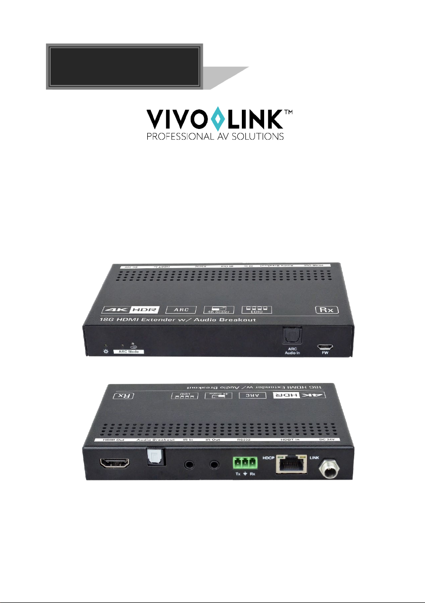
18G HDMI Receiver with Audio Breakout
All Rights Reserved
Version: VLHDMIMAT4X444-R_2019V1.3
User Manual

2
Statement
Thanks for choosing this product, please read this user manual carefully before using
this product. The functions described in this version are updated till September, 2019.
In the constant effort to improve our product, we reserve the right to make functions or
parameters changes without notice or obligation.
Safety Precaution
Do not dismantle the housing or modify the module to avoid electrical shock or
burn.
Using supplies not meeting the products' specifications may cause damage,
deterioration or malfunction.
Do not expose the unit to rain, moisture or install this product near water.
Install the device in a place with fine ventilation.
Do not twist or pull by force ends of the optical cable. It can cause malfunction.
Do not use liquid or aerosol cleaners to clean this unit.
Always unplug the power to the device before cleaning.
Unplug the power when not used for a long period of time.
Refer all servicing to qualified service personnel.
After-sales Service
We provide limited warranty for the product within three years.
Packing List
1x VLHDMIMAT4X444-R Receiver
2x Mounting Ears with 4 Screws
4x Plastic Cushions
1x 3-pin Terminal Block
1x User Manual
Note:Please contact your distributor immediately if any damage or defect in the
components is found.

3
Product Introduction
Thanks for choosing the VLHDMIMAT4X444-R HDMI 2.0 receiver which is designed to
receive 4K video from transmitter at distance up to 131 feet (40 meters) and 1080P
video at distances up to 230 feet (70 meters) over a single CATx cable. It supports
audio de-embedded and ARC. It also supports bidirectional IR and RS232 pass-
through to control source or display device remotely. PoC feature allows the transmitter
and the receiver can be powered from each other and only one power adapter is
needed in system. Moreover, the receiver supports convenient firmware upgrade
through Micro-USB port.
Features
Supports HDMI 2.0 and the HDMI video resolution up to 4K@60Hz 4:4:4 HDR.
Extends 4K signals to distances up to 131 feet (40 meters) and 1080P signals to
distances up to 230 feet (70 meters) over a single CATx cable.
Supports video resolution up-scaling, the 1080P input can be automatically
upgraded to 4K output.
SPDIF out on receiver for source audio de-embedding.
18Gbps high bandwidth.
Bidirectional IR, RS232 and 24V PoC.
Supports ARC.
Supports CEC pass-through.
Provides LEDs to indicate the current operating status.
Firmware upgrade by Micro-USB port.

4
Panel Description
1. Power LED: The LED illuminates red when power is applied.
2. ARC Mode: Press the button with paper clip or other sharp tool to enable the ARC
mode, and then the left LED illuminates blue. Press it again to exit the ARC mode
and the LED is off.
3. ARC Audio In: Toslink connector to connect ARC audio source device (e.g.TV).
4. FW: Micro-USB port for firmware upgrade.
5. HDMI Out:Type-A female HDMI output port to connect HDMI display (e.g.TV).
6. Audio Breakout: If the ARC mode is OFF, the Toslink connector is connected to
speaker or amplifier for HDMI source audio de-embedding. Note that if the ARC
mode is ON, this port has no audio output.
7. IR In: 3.5mm jack to connect the IR receiver for IR pass-through.
8. IR Out: 3.5mm jack to connect the IR emitter for IR pass-through.
9. RS232: 3-pin terminal block to connect the RS232 control device (e.g. PC) or a
third-party device to be controlled.
10. HDBT In: RJ45 port to connect the HDBT output port of transmitter by CATx
Ethernet cable. The LINK LED illuminates orange when there is a valid HDBaseT
link between the transmitter and the receiver. The HDCP LED illuminates green
when the video contains HDCP content.
11. DC 24V: DC connector for the power adapter connection.
12345678911
10

5
ARC Mode
The front panel of receiver provides a buttons to enable or disable ARC mode, as
below figure shows:
Press the button with paper clip or other sharp tool to enable the ARC mode, and then
the left LED illuminates blue. Press it again to exit the ARC mode and the LED is off.
ARC Mode
Display (e.g.TV)
Audio Transmission Path
ON
ARC is supported
The TV audio is transmitted from the TV
back to the receiver via HDMI cable, and
then it will be output by the ARC Audio
Out port of transmitter.
ARC is not supported
Connect the TV to the ARC Audio In port
of receiver with an audio cable. The TV
audio is transmitted from the TV back to
the receiver via the audio cable, and then it
will be output by the ARC Audio Out port
of transmitter.
Note that if the ARC mode is ON, the
Audio Breakout port of receiver has no
audio output.
OFF /
The TV audio can’t be back to the ARC
Audio Out port of transmitter. The Audio
Breakout port of receiver is connected to
speaker or amplifier for HDMI source audio
de-embedding.

6
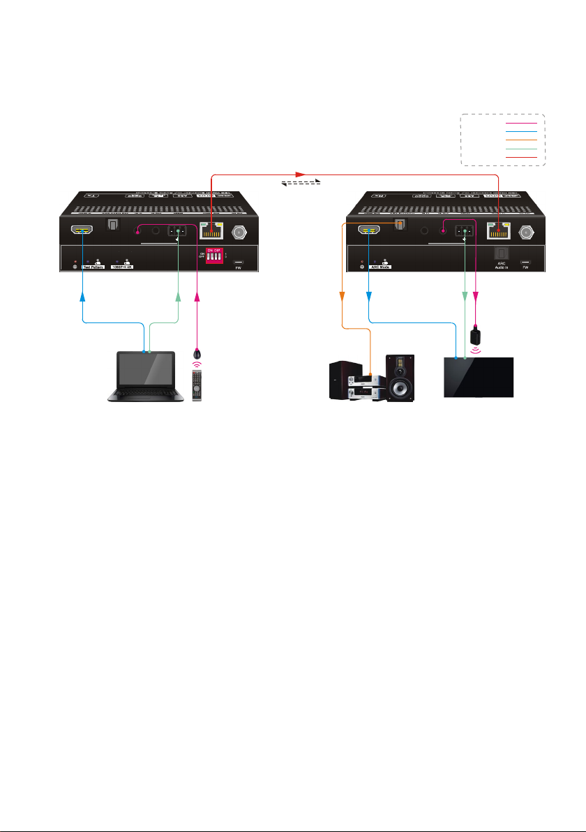
System Connection
The following diagram illustrates the typical input and output connections of the
extender:
1) The ARC mode of receiver is ON, and the display device (e.g. HDTV) supports
ARC. The TV audio is transmitted from the TV back to the receiver via HDMI cable,
and then it will be output by the ARC Audio Out port of transmitter.
Note: The STP cable is recommended to be used to ensure optimal machine
performance in ARC mode.
12 3 4
Tx Rx
LINKHDCP
Tx Rx
LINKHDCP
Speaker Laptop Remote HDTV
HDMI:
HDBaseT:
Audio:
IR:
RS232:
ARC
ARC
Tx Rx
IR
Receiver
PoC
4K 40m 1080P 70m,
IR
Emitter

7
2) The ARC mode of receiver is ON, but the display device (e.g. HDTV) doesn’t
support ARC. The TV audio is transmitted from the TV back to the receiver via the
audio cable, and then it will be output by the ARC Audio Out port of transmitter.
Note: The STP cable is recommended to be used to ensure optimal machine
performance in ARC mode.
1 2 3 4
Tx Rx
LINKHDCP
Tx Rx
LINKHDCP
Speaker Laptop Remote HDTV
HDMI:
HDBaseT:
Audio:
IR:
RS232:
ARC
Tx Rx
ARC
IR
Receiver
PoC
4K 40m 1080P 70m,
IR
Emitter
8
3) The ARC mode of receiver is OFF. The TV audio can’t be back to the ARC Audio
Out port of transmitter. The Audio Breakout port of receiver is connected to
speaker or amplifier for HDMI source audio de-embedding.
1 2 3 4
Tx Rx
LINKHDCP
Tx Rx
LINKHDCP
Laptop Remote HDTV
Speaker
HDMI:
HDBaseT:
Audio:
IR:
RS232:
Tx Rx
IR
Receiver
PoC
4K 40m 1080P 70m,
IR
Emitter

9
Technical Specification
Video
Input
(1) HDBT
Input Connector
(1) RJ45
Input Resolution
Up to 4Kx2K@60Hz 4:2:0
Output
(1) HDMI
Output Connector
(1) Type-A female HDMI
Output Resolution
Up to 4Kx2K@60Hz 4:4:4 8bit HDR10
Audio
Input
(1) ARC Audio In
Input Connector
(1) Toslink Connector
Output
(1) Audio Breakout
Output Connector
(1) Toslink connector
Audio Format
Supports PCM, Dolby Digital, Dolby True-HD, DTS and DTS-HD.
Frequency Response
20Hz – 20KHz, ±3dB
Max Output Level 2.0Vrms ± 0.5dB. 2V = 16dB headroom above -10dBV (316mV)
nominal consumer line level signal
THD+N < 0.05% (-80dB), 20Hz – 20KHz bandwidth, 1KHz sine at 0dBFS level
(or max level)
SNR
> 85dB, 20Hz-20 kHz bandwidth
Crosstalk Isolation
> 70dB, 10KHz sine at 0dBFS level (or max level before clipping)
L-R Level Deviation
< 0.3dB, 1KHz sine at 0dBFS level (or max level before clipping)
Frequency Response
Deviation
< ± 0.5dB 20Hz - 20KHz
Output Load Capability
1KΩ and higher (Supports 10x paralleled 10KΩ loads)
Stereo Channel
Separation
>70dB@1KHz
Control
Control Part
(1) ARC Mode button, (1) FW, (1) IR In, (1) IR Out, (1) RS232
Control Connector
(1) Micro-USB port, (2) 3.5mm jacks, (1) 3-pin terminal block
General
Bandwidth
18Gbps
HDMI Standard
2.0
HDCP Version
2.2, 1.4 compliant
CEC
Pass-through
Bidirectional PoC
Supported
HDMI 2.0 Cable Length
4K@60Hz 4:4:4 ≤ 5m, 4K@60Hz 4:2:0 ≤ 15m, 1080P ≤ 20m

10
Transmission Standard
HDBaseT
Transmission Distance 1080P@60Hz ≤ 230 feet (70 meters),
4K@60Hz ≤ 131 feet (40 meters)
Operation Temperature
-5~ +55
℃
Storage Temperature
-25 ~ +70
℃
Relative Humidity
10%-90%
Power Supply
Input:100V~240V AC; Output:24V DC 1.25A
Power Consumption
12W (Max)
Dimension (W*H*D)
140mm x 19.5mm x 84mm
Net Weight
290g
Note: Please adopt high-qualified HDMI cable fully compliant with HDMI 2.0 for reliable
transmission and connection.
Table of contents


