Vivosonic Integrity V500 User manual
Generation 2 (G2)
Please refer to the Integrity™ User's Manual (D-11049) for complete software operating instructions*.
*A PDF of the User's Manual is on the desktop of your Integrity™ computer.
QUICK REFERENCE

D-11049-2, Ver 11
Page 2 of 26
PLEASE READ
CAUTION
Vivosonic Integrity V500 system is a standalone test device. The notebook
computer is an integral part of the system that is customized to suit the specific
needs of the Integrity V500 software.
Do not install ANY other software other than what is supplied with your Integrity
V500 system. Failing to abide by this caution may result in system instability
and/or failure to perform.
ELECTRODES
Vivosonic recommends the Ambu® Neuroline Electrodes or the Vermed® NeuroPlus for use
with your Vivosonic Integrity V500 system. They have been tested and verified to work with
our system and provide the optimal results. To order additional electrodes please contact
Vivosonic Customer Support at: 877.255.7685 (Canada & US) or +1-416.231.9997 (Intl).
WINDOWS INTEGRITY V500 SETTINGS
Your Integrity V500 system has been optimized to work with the Windows Operating System.
Vivosonic has configured the system settings to work with the hardware and software.
Do not change any Windows settings.
For more information on default setting please contact Vivosonic Customer Support.
VIVOSONIC CUSTOMER SUPPORT
Access our FAQ information at http://www.vivosonic.com/en/support/faq.html.
877.255.7685 (Canada & US) or +1-416.231.9997 (Intl)

D-11049-2, Ver 11
Page 3 of 26
Name: Integrity™ V500 (also referred to as Integrity™, or Integrity V500, or Integrity)
REF: V500
You are licensed to use this software to operate the Integrity V500 device. You do not have
permission to use this software in any manner not related to the intended operation of this
device. You may not supply or copy this software for use by any third parties.
Integrity™ software is protected by US Pat. No. 6,778,955, 7,286,983, and 8,484,270.Other
patents pending in the U.S. and other countries.
The Amplitrode® is protected by US Pat. No. 7,206,625 and 7,548,774. Other patents
pending in the US and other countries.
Integrity™, Amplitrode®, VivoAmp™, VivoLink™, and Vivosonic™ are all either registered
trademarks or trademarks of Vivosonic Inc. in the U.S. and other countries. All other
trademarks are the property of their respective owners.
COPYRIGHT NOTICE
© 2017 This Quick reference guide is copyrighted by:
Vivosonic Inc.
222-5535 Eglinton Avenue West
Toronto ON M9C 5K5 Canada
Voice:
Fax:
Toll-free:
E-mail:
Website:
1 (416) 231.9997
1 (416) 231.2289
1 (877) 255.7685 (Canada and U.S.)
vivo@vivosonic.com (general)
www.vivosonic.com
MDSS GmbH
Schiffgraben 41
D-30175 Hannover
Germany
02864-09-05756
81763
0120

D-11049-2, Ver 11
Page 4 of 26
SAFETY
To ensure the safe operation of the Vivosonic Integrity™System, please read and comply with
the following warning and caution statements.
The following symbols will be used throughout the manual
WARNING
Messages with this heading indicate serious adverse reactions, potential safety hazards, and
limitations in use imposed by the issue labeled with a warning. The warning will identify steps
that should be taken if the incident occurs.
CAUTION
Messages with this heading indicate information regarding any special care to be exercised by
the practitioner and/or patient for the safe and effective use of the device. All precautions
should be followed to ensure data and system integrity.
ATTENTION
Messages with this heading indicate a possible loss of data. Follow the procedures to ensure
data integrity.
NOTE
Messages with this heading provide additional information that will increase the technician's
understanding of the operation of the system.
TIP
Messages with this heading provide tips or alternate instructions for a procedure.

D-11049-2, Ver 11
Page 5 of 26
GETTING STARTED
CLINICAL USE
The Integrity™ V500 system provides valuable information for estimating hearing loss, and
diagnosing cochlear and retro-cochlear function. It is intended to be used as part of a
comprehensive audiologic test battery for auditory diagnosis. It is suitable for testing patients
of all ages including newborns. To use this device properly, the operator must understand the
basics of this device's performance, and operating instructions.
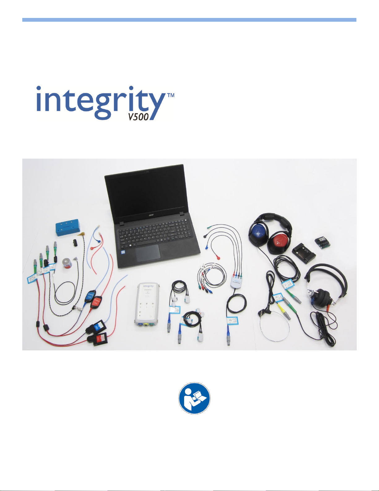
The Integrity™ V500 system is composed of a VivoLink™ with a variety of peripherals and a
computer. The Integrity™ V500 is unique in its field because of the patient interface. The
VivoLink™ and peripherals are wirelessly connected to the computer using Bluetooth®
technology. The Bluetooth connectivity allows for the patient and the VivoLink™ to be up to
30 ft. (10 m) away from the computer during testing.
BEFORE YOU BEGIN
Inspect equipment, connectors, and cables for damage.
Check that the cables to your VivoLink™ are properly connected.
Always charge your VivoLink™ batteries before use.
Clean surfaces of equipment with disinfectant.
Eliminate, where possible, the electro-magnetic noise in the room.
INSTALL THE BATTERY PACK INTO THE VIVOLINK™
Battery packs have a life expectancy of 5-7 months. You may have to replace the battery
packs after this period*.
1. Open the VivoLink™ battery compartment.
2. Remove and set aside any previously used batteries.
3. Place the battery pack in the battery compartment as shown below. Make sure to
orient the pull tab towards the outermost edge of the compartment.
*Batteries are not covered by your system warranty.
Proper insertion of battery pack
Caution
Do not hold the Vivolink™ over a baby’s body to avoid the battery pack from falling and
hurting the baby.
Integrity System Components
Pending Purchased Configuration
1. V500 (VivoLink™)
2. A81 Amplitrode® (1-channel)
3. A82 Amplitrode® (2-channel)
4. A90 VivoAmp™(1 and 2-channel)
5. VivoAmp™ Alligator clips
6. ER-3C-800 Insert Earphones
7. ER-2-800 Insert Earphones
8. ER3-60 Electrode Eartip Cables with
snaps (for EcochG)
9. H-800 EP Headphones
10. H-801 EP Headphones
11. B71W Bone Conductor
12. P81-UG OAE Probe & Holder
13. P81-GP OAE Probe & Holder
14. Integrity™Computer with Integrity™
Software
15. VivoCheck™
16. Battery pack and cradle
1
3
2
6
8
9
11
12
13
14
4
10
7
15
5
16

D-11049-2, Ver 11
Page 6 of 26
FIRST STEPS
1. Power on your VivoLink™ and computer.
2. Double-click on the Integrity™ icon ( ) to activate the Launcher,
which presents the user with the following options:
Perform Screening or Diagnostic testing.
Access learning and training materials from the Learning Library.
Configure the system.
If you have not purchased the Screening or Diagnostic test type, the
icon for that option in the Launch Bar will be disabled (grey).
3. If Screening is selected, refer to the ABR Screening section of this
guide. If Diagnostic testing is selected, read the warnings and select
Agree to continue to the Patient Window.
4. To create a new patient file you must click on an empty cell for either
Family name, Given name, or Hospital ID and enter the information.
5. Identify patient to be tested from the list by clicking on the left most
row header shown (the grey area shown below).
6. Click on the Test button to display the Test Window.
7. Select a Test Type from the side menu.
8. Wait until the initialization process is complete. This may require up to
20 to 30 seconds. The wireless (Bluetooth) connection indicator
blinks on and off during this time.
9. When initialization is completed, check the following:
The wireless (Bluetooth) connection indicator on your VivoLink™
flashes on and off and the indicator on your computer screen is
the color blue ( ).
The battery indicator on your computer, and replace the batteries
when the indicator is low ( ).
10. Select an applied protocol.
11. Prepare your patient according to the test type you have selected.
12. Initiate the test by selecting the Start button.
TIP
The Bluetooth connection safely operates
within 30 ft. (10 m) of your computer.
Caution Window
Test Window (no test selected)
Connected (ABR test selected)
Click here to select patients
Patient Window
Launcher
D-11049-2, Ver 11
Page 7 of 26
2
2
PATIENT PREPARATION FOR ABR, ABR SCREENING, ASSR, and 40 Hz ERP
One of the most important parts of obtaining quality data is the pre-test patient
preparation. This includes proper skin preparation, electrode application, and ear tip
insertion.
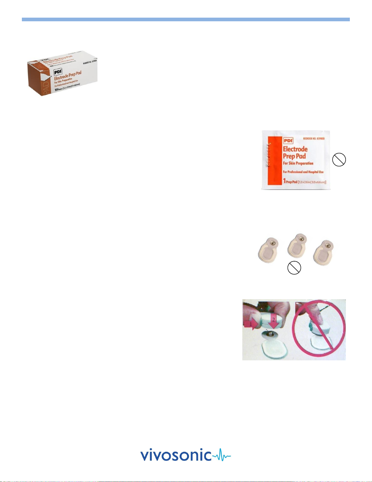
SKIN PREPARATION FOR ELECTRODE PLACEMENT
1. Check that the skin tissue is undamaged and healthy.
Do not proceed with testing if the skin is damaged or unhealthy.
2. Gently clean the electrode site with a PDI electrode Prep Pad to remove
dirt and excessive oil from the skin. The Prep Pad is intended for single use
only and should not be reused to prevent patient cross-contamination.
Apply friction (not force) when cleaning the skin.
Avoid prepping the skin too much since this can lead to adverse skin
reactions.
Use a new wipe for each electrode site.
3. Wait a few seconds until the area is dry before applying an electrode.
4. Before use, check the expiry date on the package. The electrodes have a
limited shelf life after which they start to lose their effectiveness.
SKIN ELECTRODE AND AMPLITRODE®/VIVOAMP™CLIP APPLICATION
After proper skin preparation procedures, electrodes can be attached to the
skin. The electrodes are intended for single use only and should not be reused
to prevent patient cross-contamination and to ensure good electrode skin
contact.
To apply an Ambu® Neuroline Electrode to the skin:
1. Remove the electrode from its plastic sheet.
Avoid touching the adhesive area of the electrode.
2. Place the electrode on the skin with the adhesive side down.
Apply gentle pressure on its outer edges. The entire periphery of the
electrode should be in contact with the skin.
Avoid pressing on the center of the electrode as this causes the
conductive gel to seep under the pad and will require removal and
further skin preparation.
3. Attach the Amplitrode®/VivoAmp™ clip securely to the appropriate skin
electrode site. The Amplitrode® clips use spring tension for grip. Always
use the spring release button on the Amplitrode® clips when clipping to or
unclipping from skin electrodes.
"Snap" Skin Electrodes
Do not push/pull the Amplitrode® clips
on/off skin electrodes.
D-11049-2, Ver 11
Page 8 of 26
VIVOTAB™ELECTRODE AND VIVOAMP™ALLIGATOR CLIP APPLICATION
After proper skin preparation procedures, VivoTab™ electrodes can be
attached to the skin. The VivoTab™ electrodes are intended for single use only
and should not be reused to prevent patient cross-contamination and to
ensure good electrode skin contact.
To apply a VivoTab™ Electrode to the skin:
1. Remove the electrode from its plastic sheet.
Avoid touching the adhesive area of the electrode.
2. Place the electrode on the skin with the adhesive side down.
Apply gentle pressure on its outer edges. The entire periphery of the
electrode should be in contact with the skin.
3. Attach the VivoAmp™ alligator clip securely to the appropriate skin
electrode site. The VivoAmp™ alligator clips use spring tension for grip.
Always use the spring release button on the VivoAmp™ clips when clipping
to or unclipping from skin electrodes (do not pull on the VivoTab
electrodes).
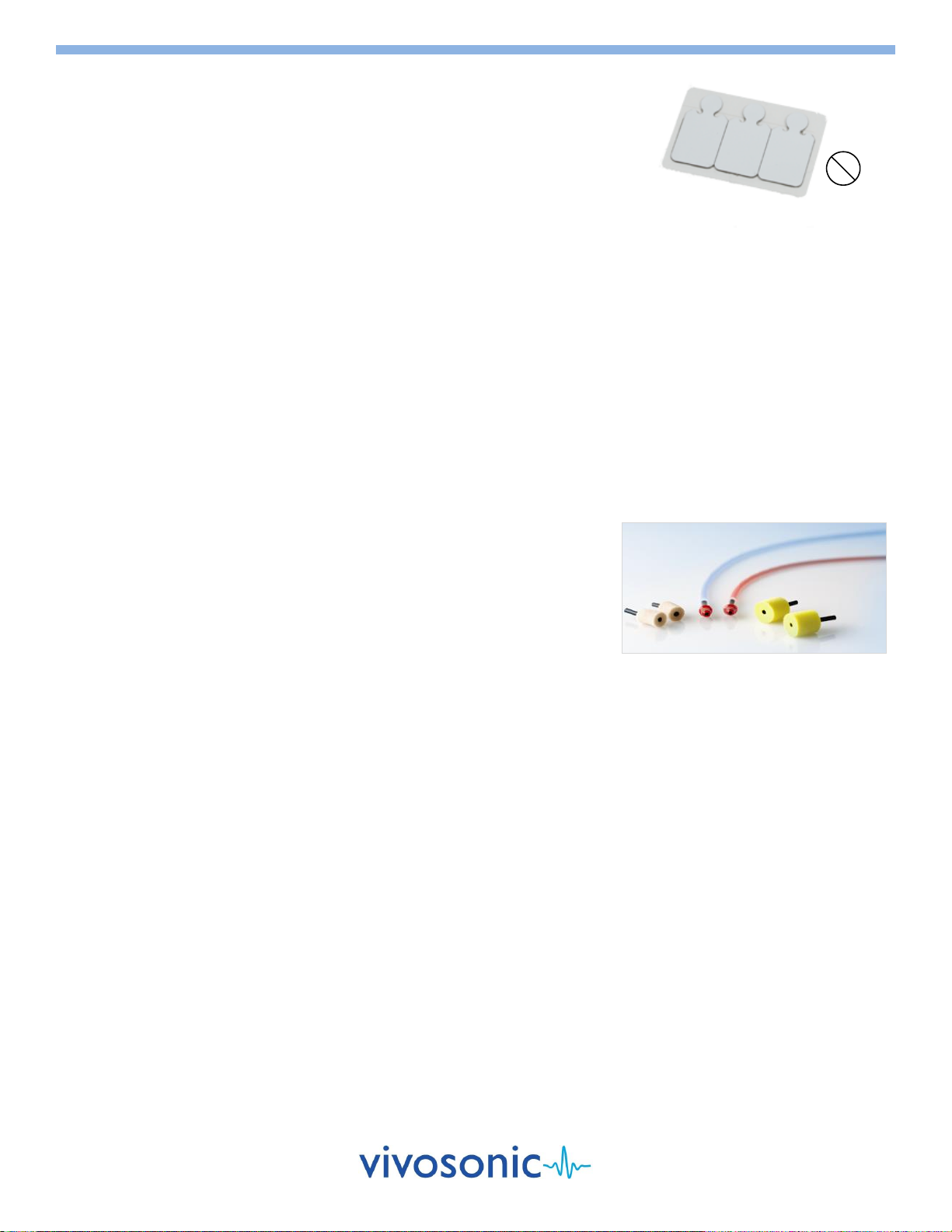
EAR TIP INSERTION
Before starting a test using Insert Earphones ear tips, the ear canal must be
clean, free of damage or disease, and clear of any obstructions to ensure good
continuity between the surface of the ear tip and the tissue of the ear.
1. Inspect the patient's ear canal for obstructions.
2. If there is an excessive deposit of earwax, have an authorized healthcare
professional remove the earwax, as defined by local healthcare
regulations.
3. Check the patient's ear canal and select an ear tip that fits tightly, yet
comfortably, in the patient's ear canal.
4. Attach the ear tips securely to the ends of the earphone tubes.
5. Roll the ear tip between two fingers and compress it.
6. Insert the ear tip slowly into the ear canal: place the red transducer into
the right ear, and the blue transducer into the left ear.
Insert Earphones Tips
2
VivoTab™ Electrode
D-11049-2, Ver 11
Page 9 of 26
AUDITORY BRAINSTEM RESPONSE (ABR)
CLINICAL USE
During ABR testing, your VivoLink™presents various auditory stimuli to your patient through air
or bone conduction such as a click or tone burst. It then records electrical responses using the
Amplitrode® or VivoAmp™ to be evaluated by the Integrity™ software. See Chapter 5 of the
User's Manual on the Computer desktop for details. For optimal results, patients should be
sleeping or quiet and relaxed, during testing.
SETUP
1. You will need:
"Snap" electrodes
A81 Amplitrode®, A82 Amplitrode®, or A90 VivoAmp™
ER-3A-800/ER-3C-800 Insert Earphones, H-800/H-801 EP Headphones, or B71W Bone Conductor
PDI electrode Prep Pads
Cotton pads or gauze
2. Connect your Insert Earphones, EP Headphones, or Bone Conductor and your Amplitrode® or VivoAmp™ to your VivoLink™.
3. Attach the tubes on the Insert Earphones if they are not already attached.
4. Select the appropriate size of ear tips for your patient.
5. Attach the ear tips securely to the ends of the earphone tubes.
CHOOSE A TRANSDUCER
ER-3A-800/ER-3C-800 Insert Earphones
Use when performing ABR testing using air conduction.
B71W Bone Conductor
Use when performing ABR bone-conduction testing.
To perform data collection, connect the B71W Bone Conductor to either the left or right mastoid or the forehead.
Secure the headband supplied with the B71W Bone Conductor. Ensure that the entire circular surface of the Bone Conductor is
in full contact with the skin. Only use the headband provided to maintain the proper sensitivity of the transducer.
H-800 Circumaural/H-801 Supra-aural EP Headphones
Use when performing ABR testing using air conduction.
Place the headphones over the ears and adjust the strap.
PREPARE THE PATIENT
Refer to the "Patient Preparation" section for:
Ear preparation and ear tip insertion
Skin preparation
Electrode application
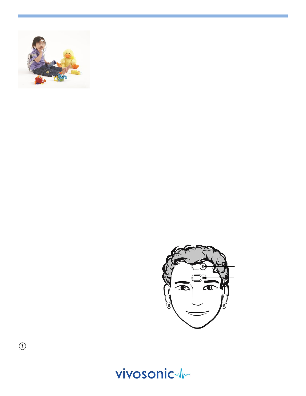
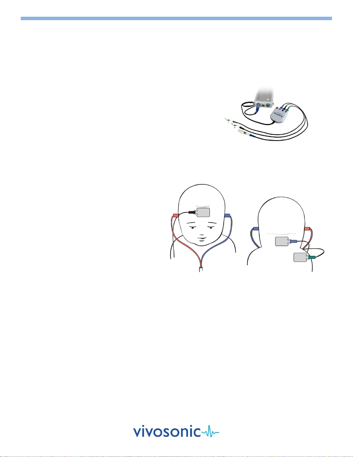
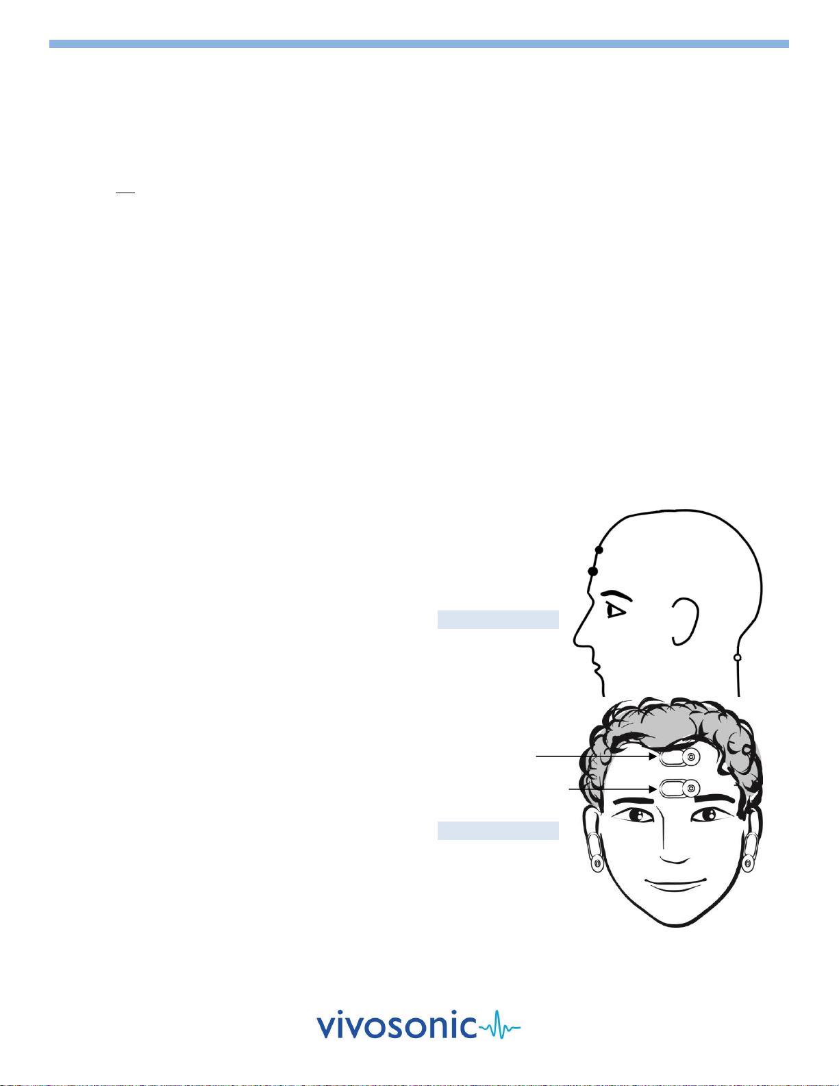
ELECTRODE SITES FOR ABR
High forehead –black clip (+)
Low forehead –green clip (ground)
For 1-channel Operation (A81)
Earlobe right or left –white clip (–)
(You can also use mastoid left or mastoid right)
For 2-channel Operation (A82/A90)
Earlobe left –blue clip (1)
Earlobe right –red clip (2)
TIP
Place the high forehead electrodes as high as possible. When possible, use the earlobe sites rather than the mastoid sites.
Also, move hair away to improve connectivity.
High Forehead (+)
Earlobe (1)
Low Forehead (Ground)
Earlobe (2)
D-11049-2, Ver 11
Page 10 of 26
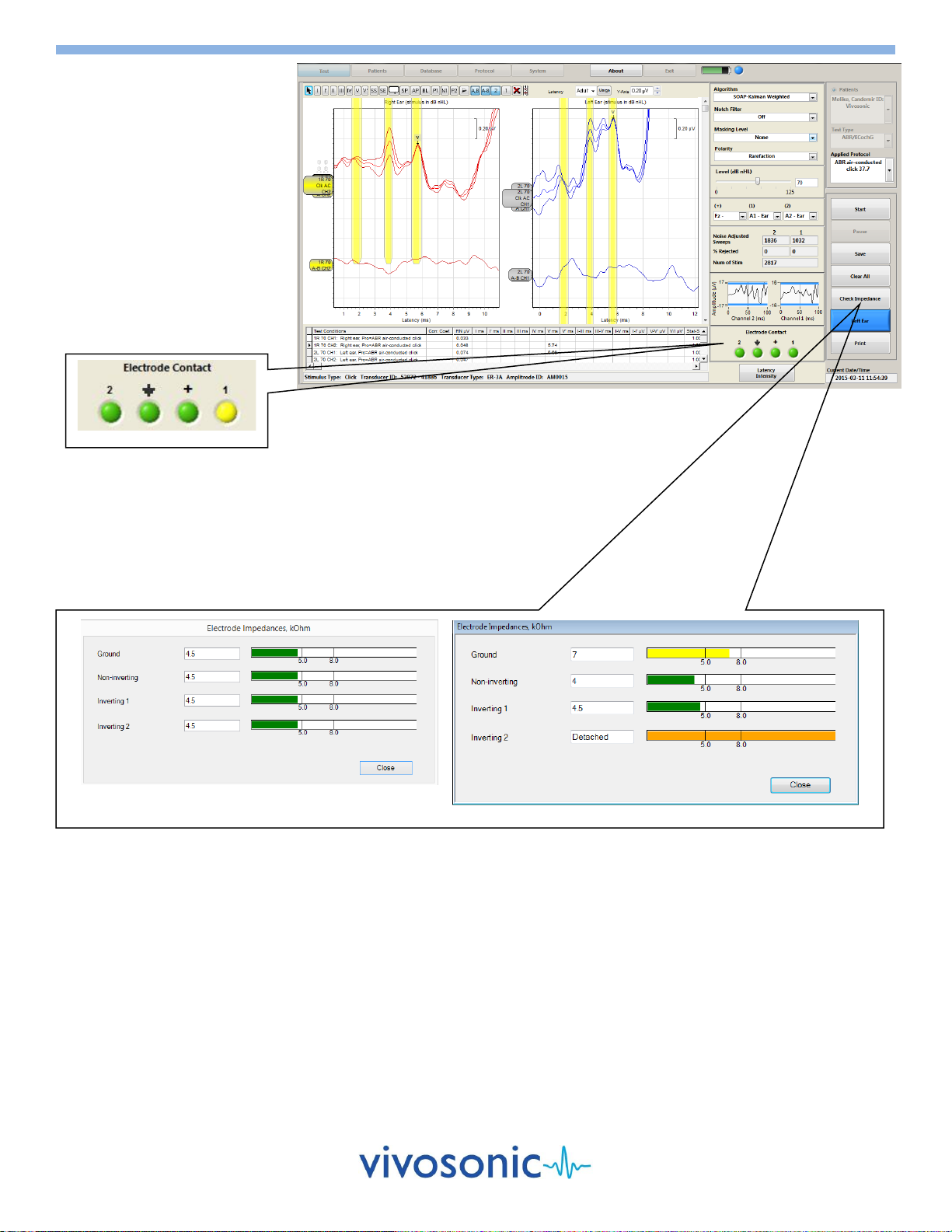
ELECTRODE CONTACT
The green lights for the ground,
(+), (1), and (2) terminals of the
electrode contact window of the
screen indicate electrode contact.
If an electrode were to fall off
during the testing, the contact
indicators would flash yellow as
displayed below. If you are using
an A81 Amplitrode, the (2)
terminal will be disabled.
If a problem is evident, remove the
electrode indicated and reapply.
CHECK IMPEDANCE
The "Check Impedance" feature will measure and display the impedance of
each patient electrode. A message will be displayed stating either that the
level is acceptable or it will indicate which electrode needs to be reapplied.
Before reapplying the electrode, repeat the skin preparation procedure. See
User's Manual on Computer Desktop.
RUN THE TEST
1. Select the appropriate protocol.
Please refer to the "Integrity™ User's Manual PDF" on the computer desktop for more detailed instruction.
2. Select the appropriate ear, choosing Right Ear or Left Ear.
3. Indicate the location of the inverting and non-inverting electrode clips.
4. Press the Start button to initiate the test.
5. After the test is complete, choose "Save" to save the record or "Clear All" to delete the record.
Acceptable level of impedance
Unacceptable impedance level
Poor Contact
ABR Test Window
D-11049-2, Ver 11
Page 11 of 26
ABR SCREENING
CLINICAL USE
ABR Screening is intended to be used with infants from 34 weeks gestational age to 6 months. For optimal results, infants should be
sleeping or quiet and relaxed, during screening. Soft clicks are delivered to the ears at sound levels of 30 or 35 dB nHL. Operators
should be trained in the proper use and care of the system.
SETUP
1. You will need:
VivoTab™ Electrodes
A90 VivoAmp™ with 3 alligator clips (Green, Black, and Blue)
ER-3C-800 Insert Earphones
PDI electrode Prep Pads
Cotton pads or gauze
2. Connect your Insert Earphones and VivoAmp™ to your VivoLink™.
3. Attach the tubes on the Insert Earphones if they are not already attached.
4. Select the appropriate size of ear tips for your patient.
5. Attach the ear tips securely to the ends of the earphone tubes.
CHOOSE A TRANSDUCER
PREPARE THE PATIENT
Refer to the "Patient Preparation" section for:
Electrode application
Ear preparation and ear tip insertion
Skin preparation
ELECTRODE SITES FOR ABR SCREENING
High forehead –black clip (+)
Shoulder –green clip (ground)
Nape of neck –blue clip (–)
RUN A SCREENING TEST
1. Select the Auto ABR Test button on the Main screen.
2. Enter information into the Patient Information screen on your computer, or select from the Patient ID list.
3. Proceed to the Test screen.
4. Select the Start Test button.
5. Wait for Integrity ABR Screening to check the set-up of your system.
6. Wait for a Pass or Refer.
Pass indicates hearing of sound
Refer indicates potential hearing loss
Incomplete indicates the test was not completed
7. Print a label. If necessary, rescreen at a later time.
8. Gently remove ear tips, then electrodes. If removal is difficult, dissolve the adhesive hydrogel with water.
9. Power off your VivoLink™ until the next patient is ready to test.
10. Clean your equipment.
A90 VivoAmp™ with alligator clips
D-11049-2, Ver 11
Page 12 of 26
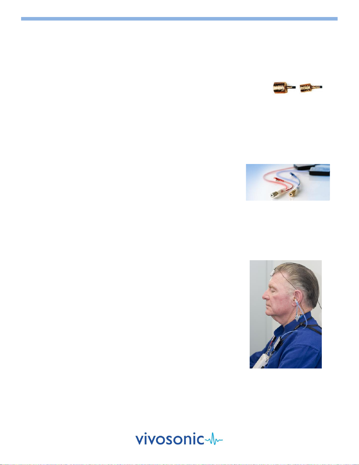
ELECTROCOCHLEOGRAPHY (EcochG)
CLINICAL USE
For EcochG testing VivoLink™presents auditory stimuli to your patient's ear through air conduction using click stimuli. It then records
electrical responses from the gold ear tip electrodes. For optimal results, patients should be sleeping or quiet and relaxed, during
testing.
SETUP
1. You will need:
One "Snap" electrode
A81 Amplitrode® or A90 VivoAmp™
ER-3A-800/ER-3C-800 Insert Earphones
ER3-26A or ER3-26B ear tips
ER3-60 Electrode Eartip Cables with snaps
PDI electrode Prep Pads
Conductive gel
Cotton pads or gauze
2. Connect your Insert Earphones and your Amplitrode® or VivoAmp™ to your VivoLink™.
3. Attach the EcochG Electrode Eartip Cables to the Insert Earphones if they are not already attached.
4. Select the appropriate size of gold electrode ear tips for your patient.
5. Attach the ear tips securely to the ends of the electrode ear tip cables.
6. Place insert through plastic tube and fasten to gold plated nipple.
7. Check that the gold-plated clips make good reliable contact with the gold foil covering
the electrode ear tips.
8. Clip the inverting (-) Amplitrode® or (1/2) VivoAmp™ clip to the snap on the cable that
corresponds to the ear to be tested to display the EcochG trace AP up.
9. Clip the non-inverting (+) Amplitrode® or (1/2) VivoAmp™ clip to the snap on the cable
that corresponds to the other ear.
Use the reverse set up to get the EcochG trace AP down.
APPLY GROUND ELECTRODE AND CLIP FOR 1-CHANNEL ECOCHG(A81/A90)
For EcochG testing, one snap electrode is applied to the low forehead of your patient. This
electrode functions as the ground electrode. The green Amplitrode® or VivoAmp™ clip is
attached to this electrode.
GOLD ELECTRODE EAR TIP INSERTION
1. The Ear Canal must be completely unobstructed for a successful result.
2. Coat the ear tip thinly with conductive gel.
3. Hold the ear tip with two fingers and gently compress it.
Avoid damaging the gold foil.
4. Carefully insert the ear tip into the ear canal.
Red transducer into the right ear.
Blue transducer into the left ear.
The ear tip should fit snugly, yet comfortably.
5. Wait until the ear tip has completely expanded in the ear canal.
6. Check that the gold-plated clips continue to have good contact with the gold foil of the
ear tips.
RUN THE TEST
1. Select the appropriate protocol.
Please refer to the "Integrity™ User's Manual PDF" on the computer desktop for more detailed instructions.
2. Press the Start button to initiate the test.
3. After the test is complete, choose "Save" to save the record or "Clear All" to delete the record
Gold foil covered ear inserts
attached to cable
Setup
ER3-26A & ER3-26B
ear tips

D-11049-2, Ver 11
Page 13 of 26
AUDITORY STEADY-STATE RESPONSE (ASSR)
CLINICAL USE
ASSR testing produces frequency-specific information, and provides an objective and accurate estimate of the behavioral pure-tone
audiogram. It is well-suited for testing infants, young children, and other individuals unable to provide reliable behavioral responses.
See Chapter 7 of the User's Manual on Computer Desktop for details. For optimal results, patients should be quiet and relaxed
during testing. For 80 Hz ASSR, patients may be sleeping; but, for 40 Hz ASSR, patients should not be sleeping.
SETUP
1. You will need:
"Snap" electrodes
A81 Amplitrode®, A82 Amplitrode®, or A90 VivoAmp™
ER-3A-800/ER-3C-800 Insert Earphones or H-800/H-801 EP Headphones
PDI electrode Prep Pads
Cotton pads or gauze
2. Connect your Insert Earphones or EP Headphones and your Amplitrode® or
VivoAmp™ to your VivoLink™.
3. Attach the tubes on the Insert Earphones if they are not already attached.
4. Select the appropriate size of ear tips for your patient.
5. Attach the ear tips securely to the ends of the earphone tubes.
ENVIRONMENT FOR AN ASSR TEST
Adult Patient or an Older Child
The patient may be placed in a chair or on a couch, whichever is more comfortable for the patient and the operator.
Tests are conducted with the patient relaxed, lying down or in a chair with the neck supported. Patients are encouraged to
sleep during the test.
Infant Patient
Tests are conducted with the infant sleeping or lying down and very relaxed.
Place the VivoLink™ next to the infant close enough for the Amplitrode® or
VivoAmp™ and Insert Earphones or EP Headphones cables to reach.
PREPARE THE PATIENT
Refer to the "Patient Preparation" section for:
Ear preparation and ear tip insertion
Skin preparation
Electrode application
ELECTRODE SITES FOR ASSR
High forehead –black clip (+)
Low forehead –green clip (ground)
For 1-channel Operation (A81)
Nape –white clip (–)
For 2-channel Operation (A82/A90)
Earlobe left –blueclip (1)
Earlobe right –red clip (2)
RUN THE TEST
1. Perform an impedance check (see previous section).
Good impedance is crucial for ASSR testing.
2. Select the appropriate protocol and montage.
Please refer to the "Integrity™ User's Manual PDF" on the computer desktop for more detailed instructions.
3. Press the Start button to initiate the test.
4. After the test is complete, choose "Save" to save the record or "Clear All" to delete the record.
High Forehead (+)
Nape (–)
Low Forehead (Ground)
1-channel Montage
2-channel Montage
High Forehead (+)
Earlobe (1)
Low Forehead (Ground)
Earlobe (2)
D-11049-2, Ver 11
Page 14 of 26
TRANSIENT EVOKED OTOACOUSTIC EMISSIONS (TEOAE)
DISTORTION PRODUCT OTOACOUSTIC EMISSIONS (DPOAE)
CLINICAL USE
For TEOAE testing, VivoLink™ generates a click signal via the OAE probe. This evokes an otoacoustic emission
response (OAE) from the cochlea of the inner ear which is recorded by Integrity™ to assess cochlear hair cell
function.
For DPOAE testing, VivoLink™ generates two pure tones (primaries) that are presented simultaneously to the
cochlea via the OAE probe. This evokes an intermodulation distortion product that is generated by the human
cochlea and recorded by Integrity™ to be used to assess cochlear hair cell function.
Currently there are two different OAE probes available for the Integrity™ V500. These probes
have similar functionality and the choice is based on user preference. The P81-GP OAE probe is
Vivosonic's original probe design. The P81-UG OAE probe is a new version of probe design.
Refer to Chapter 8 and 9 of the User's Manual on the Computer Desktop for details.
SETUP
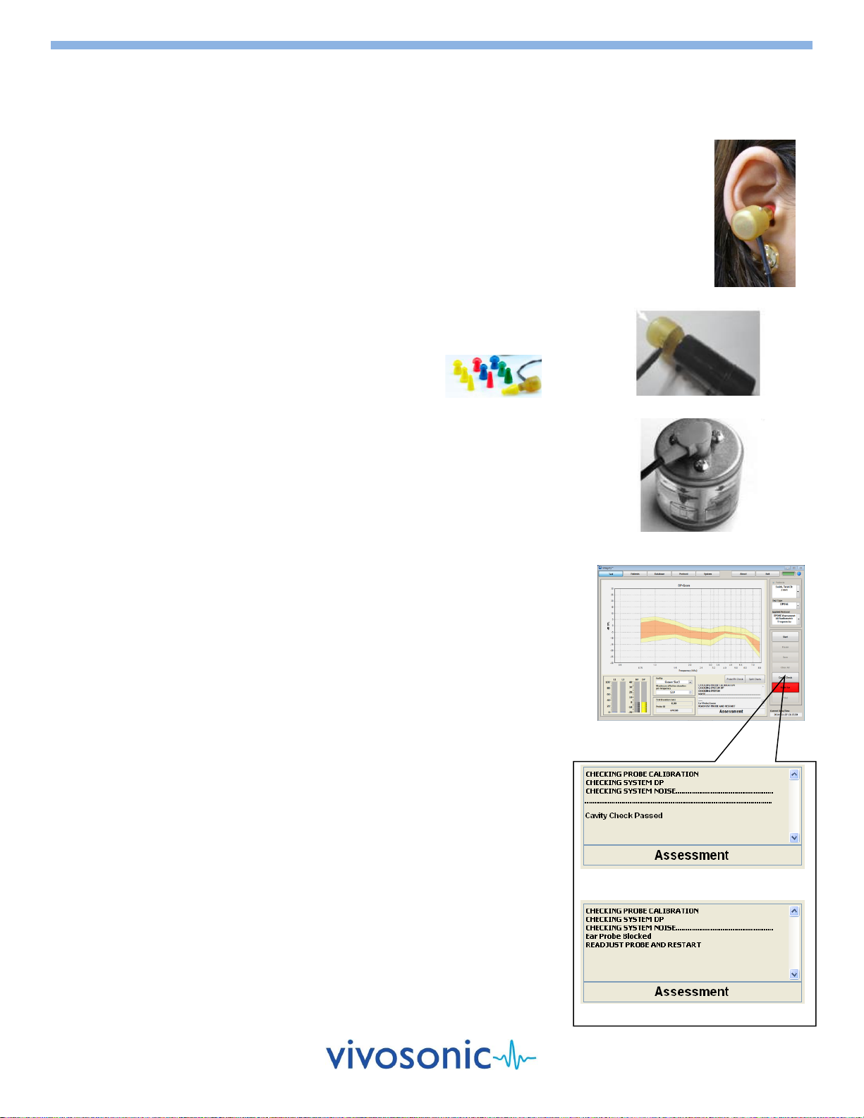
1. You will need: Eartips. Ex. GP Eartips.
2. Connect either of the OAE probes to your VivoLink™.
CAVITY CHECK
Before you begin testing, you can perform a cavity check to ensure that your OAE probe
is correctly calibrated.
1. Place your OAE probe into the OAE probe holder.
2. Select the Cavity Check button on the Test Window.
3. Wait for the results to appear in the message area of the Test Window.
4. You can proceed with testing when the messages indicate "Cavity Check Passed".
If cavity check fails, inspect the probe for debris and clean the probe if
necessary. Reinsert the OAE probe into the holder and run the test again. Refer
to User's Manual for more detail.
OAE PROBE INSERTION
Inspect your patient's ear canal to ensure there is no obstruction.
1. Do not proceed with testing if the ear canal is blocked.
2. Select the appropriate ear tip according to the size of the ear canal.
3. Attach the ear tip to the OAE probe.
4. Slowly and carefully insert the probe and ear tip into the ear canal.
Insert the ear tip slowly to avoid excessive air pressure in the ear canal.
The ear tip should fit snugly yet comfortably.
RUN THE TEST
1. Select the appropriate protocol.
Please refer to the "Integrity™ User's Manual PDF" on the computer desktop
for more detailed instructions.
2. Select the appropriate ear, choosing Right Ear or Left Ear.
3. Press the Start button to initiate the test.
4. After the test is complete, choose "Save" or "Clear All" to delete the record.
Select "Cavity Check"
Cavity Check - Fail
Cavity Check –Pass
OAE Probe P81-GP Cavity Check
OAE Probe P81-UG Cavity Check
D-11049-2, Ver 11
Page 15 of 26
40 Hz EVENT-RELATED POTENTIAL (40 Hz ERP)
CLINICAL USE
The 40 Hz ERP is recorded from the scalp when a stimulus with a repetition rate of approximately 40 Hz is applied. The stimulus is a
composite of pure tones modulated at 40 Hz. The 40 Hz ERP primarily represents mid-latency response peaks that are separated by
approximately 25 ms, the 40 Hz period. The 40 Hz ERP can be used to estimate the threshold of hearing but it may be significantly
affected by the patients′ attention, state of consciousness and age. For optimal results, patients should be quiet and relaxed during
testing, but not sleeping.
SETUP
1. You will need:
"Snap" electrodes
A81 Amplitrode®, A82 Amplitrode®, or A90 VivoAmp™
ER-3A-800/ER-3C-800 Insert Earphones or H-800/H-801 EP Headphones
PDI electrode Prep Pads
Cotton pads or gauze
2. Connect your Insert Earphones or EP Headphones and your Amplitrode® or VivoAmp™ to your VivoLink™.
3. Attach the tubes on the Insert Earphones if they are not already attached.
4. Select the appropriate size of ear tips for your patient.
5. Attach the ear tips securely to the ends of the earphone tubes.
ENVIRONMENT FOR A 40 HZ ERP TEST
Adult Patient or an Older Child
The patient may be placed in a chair or on a couch, whichever is more comfortable for the patient and the operator.
Tests are conducted with the patient relaxed, lying down or in a chair with the neck supported. Patients should remain awake.
Infant Patient
40 Hz ERP testing may not yield repeatable results in infants. If, nevertheless,
you wish to conduct tests on infants, conduct the tests with the infant lying
down and very relaxed but not while the infant is sleeping.
Place the VivoLink™ next to the infant, close enough for the Amplitrode® or
VivoAmp™ and Insert Earphones or EP Headphones cables to reach.
PREPARE THE PATIENT
Refer to the "Patient Preparation" section for:
Ear preparation and ear tip insertion
Skin preparation
Electrode application
ELECTRODE SITES FOR 40 HZ ERP
High forehead –black clip (+)
Low forehead –green clip (ground)
For 1-channel Operation (A81)
Nape –white clip (–)
For 2-channel Operation (A82/A90)
Earlobe left –blue clip (1)
Earlobe right –red clip (2)
RUN THE TEST
1. Perform an impedance check (see previous section).
Good impedance is crucial for 40 Hz ERP testing.
2. Select the appropriate protocol.
Please refer to the "Integrity™ User's Manual PDF" on the computer desktop for more detailed instructions.
3. Press the Start button to initiate the test.
4. After the test is complete, choose "Save" to save the record or "Clear All" to delete the record.
High Forehead (+)
Low Forehead (Ground)
Nape (–)
1-channel Montage
2-channel Montage
High Forehead (+)
Earlobe (1)
Low Forehead (Ground)
Earlobe (2)

D-11049-2, Ver 11
Page 16 of 26
WORKING WITH YOUR DATABASE
Your Integrity™ system uses a database to store patient and test
data for future analysis. The Database Window retrieves this data
and provides tools to review and analyze your patient's test results.
From the database, you can also query, print, export, delete, and
archive test records. Refer to Chapter 4 of the User's Manual on the
Computer Desktop for details about the Database and other screens.
VIEW YOUR DATABASE
1. Select the Database tab.
2. Enter your password. Your password is case-sensitive. It is set in
the System Window. The default password is blank.
3. Highlight a record in the database by clicking on the leftmost row
header (grey area) to preview the test results. Each test type has a
different database preview window seen in the figures below.
QUERY THE DATABASE
1. Select a column in the query area of the Database Window.
For example, "Patient Info" is a common column to query.
2. Select a value from the dropdown list to view a subset of the
records in your database.For example, select the name of a
patient to view only the records for that patient.
ABR Database Preview
ECochG Database Preview
TEOAE Database Preview
DPOAE Database Preview
Query Area of Database Window
Database Window
Click here to select patients
TEOAE Database Preview
D-11049-2, Ver 11
Page 17 of 26
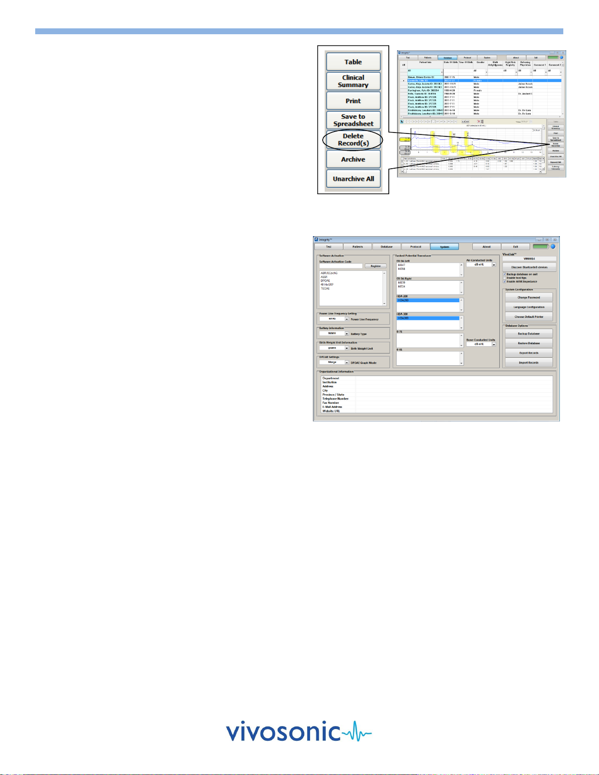
DELETE RECORDS
1. You may first want to back up your database using the Backup
Database function on the System Window (see below).
2. Identify your patient from the list by clicking on the left most
row header shown (the grey area).
To select more than one patient, hold the Ctrl key and
click on the desired row header.
To select a range of patients, hold the Shift key and click
on the last patient in the group.
3. Select the Delete Records(s) button to permanently remove
the selected records from your database.
BACKUP AND RESTORE YOUR DATABASE
The backup feature makes a copy of your entire database. To
prevent permanent loss of data due to hard drive failure, it is
recommended that your database be backed up regularly. The
system backs up automatically as well when the system is closed.
BACKUP YOUR DATABASE
1. Select the System button to display the System Window.
2. Select the Backup Database button.
3. Complete the Save Backup File As window with the location
and name of your .BAK backup file.
RESTORE YOUR DATABASE FROM A PREVIOUS BACKUP
1. Select the System button to display the System Window.
2. Select the Restore Database button.
3. Specify the location and name of the desired .BAK backup file.
Note: Restoration of your database will overwrite your existing
database.
OTHER FUNCTIONS
For information regarding exporting data, printing forms, archiving records, or merging records, please refer to the "Integrity™
User's Manual PDF" on the computer desktop for more detailed instructions.
System Window
Database Window

D-11049-2, Ver 11
Page 18 of 26
INSTRUCTIONS FOR USING THE BATTERY PACK CHARGING SYSTEM
Components of Battery Pack Charging System
CHARGING THE BATTERY PACK USING THE BATTERY PACK CRADLE
Prior to using the Battery Pack(s), please fully charge the battery using the Battery Charger and the Battery Pack Cradle as follows:
Attach the silver connector on the Battery Charger to the silver port on the Battery Pack Cradle.
Place the Battery Pack in the Battery Pack Cradle so that the + and –icons on the Battery Pack and the Battery Pack Cradle
point in the same direction.
Plug the power lead on the Battery Pack Charger to a wall socket.
WARNING
*** WHEN CHANGING BATTERY PACK TO RECHARGE, UNPLUG THE BATTERY CHARGER FROM THE WALL, PLACE THE NEW
BATTERY PACK INTO THE CRADLE AND THEN PLUG THE CHARGER BACK INTO THE WALL. THE LED LIGHT WILL SHOW
ORANGE or GREEN/ORANGE WHEN CHARGING. While the Battery Pack is charging, do not simultaneously touch the
patient (or earth ground) AND either a) the Battery Pack terminals, or b) the Battery Pack Cradle terminals.
Use only Vivosonic Battery Packs (REF 100020). Use of other batteries may damage the charging system and/or the
batteries, and endanger the user.
Use only the Battery Charger (REF 100351) and Battery Pack Cradle (REF 100410), supplied with your product, to charge the
Vivosonic Battery Packs (REF 100020). Do not use the Battery Charger (REF 100351) and Battery Pack Cradle (REF 100410)
to charge any other batteries.
The Battery Packs are meant to be replaced after about five to seven months of regular use. Please ensure that local laws
are obeyed when disposing these Battery Packs. Do not discard batteries into unsorted municipal waste.
Ensure that the Battery Packs are inserted in the correct orientation when placed in the Battery Pack Cradle and when
placed in the medical device.
The Charging System should not come in contact with any liquids, or be exposed to extreme humidity. Discontinue use of
the Charging System if any one of these conditions occurs and contact Vivosonic's technical support team for further
assistance, 1-877-255-7685 (Canada & US), 1-416.231.9997 (Intl).
Remove the Battery Pack from the VivoLink™when the Integrity product is not in use.
Batteries are not covered by your system warranty.
Battery Pack Cradle (REF 100410)
Battery Pack (x2) (REF 100020)
Battery Charger (REF 100351)
LED:
Green - Charged
Orange - Fast Charge
Green / Orange –Top-off Charge

D-11049-2, Ver 11
Page 19 of 26
ADDITIONAL PRECAUTIONS AND WARNINGS
WARNING: CONTRAINDICATIONS
This device is contraindicated for patients with these conditions:
Patients who display signs of excessive earwax
If, upon inspection, it appears that excessive earwax is present, DO NOT insert the ear tip in the ear canal. Inserting the ear tip could force earwax
to press against the eardrum resulting in damage to the ear. It could also cause incorrect measurements and lead to an incorrect assessment.
Patients with inflammation of the ear canal
If, upon inspection, it appears that the skin of the ear canal has signs of inflammation, DO NOT use this device. The ear tip will cause slight pressure
that may cause mild abrasion and pain.
Patients who have ear canal blockage due to foreign particles
If, upon inspection, it appears that any foreign particles are present in the ear canal or any foreign particles block access to the eardrum, DO NOT
insert the ear tip into the patient's ear.
Patients who display signs of discharge in the ear
If, upon inspection, any discharge is observed, DO NOT insert the ear tip into the patient's ear.
Patients who display skin damage
If a patient displays any signs of skin damage at the site of an electrode application (such as skin irritation (redness), scratches, bruises, sores, cuts,
wounds, bleeding), DO NOT conduct skin preparation and application of the electrodes for ABR testing. Consult a dermatologist or other trained
health-care professional.
Patients with involuntary sudden head motions
Do NOT place the insert earphones, gold electrode ear tip, or the OAE Probe, in the ear of patients who have involuntary sudden head motions.
Such a motion could result in a self-inflicted injury of the inner ear.
Patients who cannot be still
Do NOT place the insert earphones, gold electrode ear tip, or the OAE Probe in the ear of a patient who is actively resisting insertion or displays
involuntary movements. Such a motion could result in a self-inflicted injury of the inner ear.
WARNING
General Testing
Testing is to be performed by a trained healthcare professional licensed by local authorities.
This equipment is not suitable for use in the presence of an inflammable anesthetic mixture with air, oxygen or nitrous oxide.
Changes or modifications not expressly approved by Vivosonic Inc. could void the user's authority to operate the equipment.
To avoid accidental swallowing of inhalation of an ear tip, do not leave ear tip(s) within reach of a child. Patients should be attended
during preparation and testing.
Tympanic membrane and inner ear damage may occur resulting in possible infection and hearing loss. Cleaning of the ear canal and
insertion of the electrode ear tip should be performed by a trained and licensed healthcare professional.
DO NOT force the ear tips into the patient's ear canal. Excessive force could cause damage to the Tympanic membrane, rupturing the
eardrum and possibly damaging the inner ear, which could result in infection and hearing loss.
Simultaneous connection of a patient to high frequency (HF) surgical equipment and evoked response equipment (this equipment) may
result in burns at the site of the skin electrodes, as well as possible damage to this equipment.
If at least one applied part (such as an Amplitrode®electrode lead) is connected to the patient, do not let any other applied part contact
other conductive parts, including earth ground.
If at least one applied part (such as an Amplitrode®electrode lead) is connected to the patient, and the patient is also wearing the Bone
Conductor, make sure the Bone Conductor plug contacts only its connector on the VivoLink, not any other conductive parts, including
earth ground.
ABR Testing
The bone conductor headband is a steel spring designed to hold the bone conductor in place using no more than hand-tightened force.
The headband may injure the patient if it is released before full contact with the skin. When placing the bone conductor on the patient's
head, do not release the headband until both the bone conductor and the opposite cushioned pad are in full contact with the skin.
oStrangulation may occur.
oDo not put the B71W Bone Conductor cable around the patient's neck.
oDo not leave a patient unattended while preparing and conducting the bone-conduction test.
EcochG Testing
Removing the gold electrode ear tip from the ear canal too quickly may cause a negative air pressure in the occluded ear canal and result
in injury to the eardrum.

D-11049-2, Ver 11
Page 20 of 26
WARNING
Hazard: The patient experiences discomfort when the ear tip is inserted into the ear canal.
Remedy: The operator must check whether the ear tip selection is incorrect and replace with a properly fitting ear tip.
Hazard: Audible levels are uncomfortable for the patient.
Remedy: The operator must immediately select a lower setting for the stimulus levels.
Hazard: In ABR testing skin at the site of the electrode application is damaged, for example, irritated (red), scratched, bruised, sore, cut, wounded,
or bleeding.
Remedy: Do not conduct skin preparation and electrode application on areas of damaged skin. Choose another electrode location, wait until
healing is complete, consult a dermatologist, or refer the patient to a healthcare professional trained to deal with skin damage.
WARNING
Electronic Disposal
DO NOT dispose of equipment in unsorted, municipal garbage.
Take discarded equipment to the appropriate electronic waste disposal facility.
Environmental Conditions for Transport and Storage
Integrity (with Battery Pack)
Integrity (without Battery Pack)
Ambient temperature of -20 C to +50 C (for 30 days)
Ambient temperature of -20 C to +40 C (for 90 days)
Ambient temperature of -20 C to +30 C (for 1 year)
Relative humidity of 10% to 100%
Atmospheric pressure range of 500 hPa to 1060 hPa
Ambient temperature of -40 C to +70 C
Relative humidity of 10% to 100%
Atmospheric pressure range of 500 hPa to 1060 hPa
Environmental Conditions for Use
Ambient temperature of 10 C to 39 C
Relative humidity of 30 % to 75 %
Atmospheric pressure range of 700 hPa to 1060 hPa
CAUTION
Following the "Guidance for Industry, FDA Reviewers and Compliance on Off-The-Shelf Software Use in Medical Device", issued by FDA on
September 9, 1999, the customers should not use any software other than that specified, as it will violate the safety, effectiveness and design
controls of our Integrity V500 and that such use may result in an increased risk to users and patients.
Unauthorized alteration of software provided, including downloading non-validated or unauthorized off-the-shelf software may void or breach
existing service agreements and warranties. For additional information, contact Vivosonic Inc.'s Customer Support.
CAUTION
Please follow these recommendations to ensure the test data is accurate.
Substitution of any supplied components with different components may result in measurement error.
No other software may be installed onto the computer on which the Integrity™ software is installed.
Handle the system with care.
The system requires calibration of the transducers –A81/A82 Amplitrodes, A90 VivoAmp, Insert Earphones, B71W Bone Conductor, OAE
probes, and EP headphones –annually on each anniversary from the date of manufacture, and every time a transducer is dropped,
subjected to mechanical shock, or immersed in a liquid substance. Otherwise, stimuli presented to the patient as specified may lead to
incorrect test results and misdiagnoses.
DO NOT force the ear tip into the ear canal.
Always carry this device with you when traveling to avoid mishandling and damage of stored or checked luggage.
DO NOT ship this device for service in packaging other than the packaging supplied with the system from the manufacturer, or
comparable packaging.
Signal inputs and outputs are intended for analysis only in connection to the specified equipment described in this manual.
The product DOES NOT require sterilization. Alcohol can be used to clean the transducers.
This equipment does not have protection against water penetration (IPX0).
The system can only be repaired by Vivosonic Inc. or authorized dealers of Vivosonic Inc.
Table of contents


