NOVOTEST UT-3M-EMA User manual
Operating manual
(Electromagnetic-acoustic) EMA Thickness
Gauge NOVOTEST UT-3M-EMA
Postal address and registered address:
51200, Novomoskovsk, Spasskaya Str., 5
Sales office:
landline: +38-056-767-23-25 (multichannel)
mobile: +38-067-565-82-33
http://novotest.ua/
Warranty repair and servicing:
tel. +38-056-767-20-25

RDC.ED.UT-3M-EMA.000 OM
Operating manual
EMA Thickness Gauge NOVOTEST UT-3M-EMA
Page. 2
CONTENTS
1 Description and operation of the device and its components.................................................................4
1.1 Intended use ....................................................................................................................................4
1.2 Device specifications ......................................................................................................................4
1.3 Package ...........................................................................................................................................5
1.4 Device components.........................................................................................................................5
1.5 Transducer.......................................................................................................................................6
1.6 Structure and functioning................................................................................................................7
1.7 Operating modes.............................................................................................................................7
1.8 Means of measurement, device, and accessories............................................................................8
1.9 Marking...........................................................................................................................................8
1.10 Packaging......................................................................................................................................8
2 Intended use ...........................................................................................................................................9
2.1 Operating restrictions......................................................................................................................9
2.2 Preparation for the use ....................................................................................................................9
2.2.1 Visual inspection......................................................................................................................9
2.2.2 Battery charging.......................................................................................................................9
2.2.3 Transducer connection.............................................................................................................9
2.3 Operation.......................................................................................................................................10
2.3.1 Turning on..............................................................................................................................10
2.3.2 “MEASUREMENT” mode....................................................................................................11
2.3.3 “SETTINGS”mode ...............................................................................................................16
2.3.4 “ARCHIVE”mode ................................................................................................................17
2.3.5 “INFORMATION”mode......................................................................................................17
2.3.6 Measurement..........................................................................................................................18
3 Maintenance of the device and its components ...................................................................................19
3.1 Safety precautions.........................................................................................................................19
3.2 Warranty........................................................................................................................................19
3.2.1 Basic warranty........................................................................................................................19
3.2.2 Extended warranty .................................................................................................................19
3.2.3 Warranty for repaired and replaced components ...................................................................19
3.2.4 Wearing parts.........................................................................................................................19
3.2.5 Owner obligations..................................................................................................................20
3.2.6 Warranty obligations..............................................................................................................20
3.2.7 Cases uncovered by warranty ................................................................................................21
3.2.8 Other warranties and consumer law.......................................................................................21
3.3 Maintenance..................................................................................................................................21
4 Running repairs....................................................................................................................................23
5 Storage .................................................................................................................................................23
6 Transportation......................................................................................................................................23
7 Disposal................................................................................................................................................23

RDC.ED.UT-3M-EMA.000 OM
Operating manual
EMA Thickness Gauge NOVOTEST UT-3M-EMA
Page. 3
Caution!
Please read this operating manual carefully before operating electromagnetic-acoustic (EMA)
thickness gauge NOVOTEST UT-3M-EMA.
Operating manual (hereinafter referred to as OM) includes the information required to inform
operator about the performance and operating procedure of the device –EMA Thickness Gauge
NOVOTEST UT-3M-EMA (hereinafter referred to as the device or thickness gauge). The document
contains the specification, description of the design and operating principle, as well as the information
necessary for the right product operation. Before using the device, operator must read this manual, as
the device must be operated by a person aware of the operating principle and design of the device.
The right and efficient operation of the device requires:
measurement technique;
conditions of measurement that meet the measurement technique;
a trained operator who read this operating manual.
NOVOTEST reserves the right to make minor changes that do not impair the technical
specification of the product. These changes may not be mentioned in this document.
The delivery set of the device includes the operation documents that are a part of this manual and
the device registration certificate.
This OM applies to all product modifications.

RDC.ED.UT-3M-EMA.000 OM
Operating manual
EMA Thickness Gauge NOVOTEST UT-3M-EMA
Page. 4
1 DESCRIPTION AND OPERATION OF THE DEVICE AND ITS COMPONENTS
1.1 Intended use
Electromagnetic-acoustic (EMA) thickness gauge NOVOTEST UT-3М-EMA is intended for
measuring the wall thickness of metal and alloy parts, walls of steel pipes, flat-rolled stock, rods, etc.,
without the use of couplant and preliminary surface preparation. EMA Thickness Gauge allows testing
through a gap that might be air, rust, paint coating, fluid, plastic, salt deposits, etc.
The thickness gauge can be used in engineering, aerospace, metallurgy, in the mounting of metal
structures, thermal power plants and nuclear power plants, field laboratories, and in the testing of
vehicles.
1.2 Device specifications
Electromagnetic-acoustic (EMA) thickness gauge NOVOTEST UT-3М-EMA is a portable device
enclosed in a shockproof casing with the chipboard, electronic components, and lithium-ion battery.
The product specifications are shown in the tab. 1.1.
Table 1.1 –Device specifications
Measurement range (depending on a transducer), mm
0.6 - 200
Permissible error, mm
(0.01h + 0.05)
where: h –nominal thickness, mm
Ultrasound velocity range, m/s
100 - 9999
Resolution, mm
0.01
Measurement modes
Autocorrelation (ACF)
Echo
Echo-Echo (dual echo)
Pique-Pique
Dimensions of the processing unit, max, mm
165х90х50
Power type
a built-in lithium-ion battery
Worktime without charging, min, h
8
Weight of the processing unit, max, kg
0.45
Display size
3.5 inches
Operating temperature range of the processing unit, °С
from -20 to +50
Air humidity, max
98 %, at 35 °С

RDC.ED.UT-3M-EMA.000 OM
Operating manual
EMA Thickness Gauge NOVOTEST UT-3M-EMA
Page. 5
1.3 Package
The processing unit of EMA Thickness Gauge UT-3М-EMA...............................................1 pc.
EMA transducer ..........................................................................................................As per order
2Lemo-2Lemo cable ...................................................................................................As per order
USB cable................................................................................................................................1 pc.
Charger....................................................................................................................................1 pc.
Packaging container ................................................................................................................1 pc.
Operating manual RDC.ED.UT-3М-EMA OM......................................................................1 pc.
Registration certificate RDC.ED.UT-3М-EMA RS ...............................................................1 pc.
* By a customer request, additional equipment or parts can be included in the package. The exact
information on the scope of delivery is specified in the registration certificate of the device.
1.4 Device components
The device consists of a processing unit enclosed in a durable and lightweight aluminum case, and
a transducer connected via sockets. The thickness gauge is controlled from the keyboard. Signals and
readings, the status of the device and other information are presented on a contrast color LCD / TFT
display.
The transducers are connected via coaxial cables, through the connectors that are located on the
top panel of the housing. The device is powered by a lithium-ion battery. The mini-USB connector,
located on the bottom of the case, is used to connect the device to a PC and to charge the battery. In
fig. 1.1 shows the components of the device.
1
2
3
4
5
1 –casing; 2 –contrast color LCD/TFT display; 3 –keyboard; 4 –transducer connection sockets;
5 –mini-USB slot.
Figure 1.1 –Electromagnetic-acoustic (EMA) thickness gauge NOVOTEST UT-3М-EMA

RDC.ED.UT-3M-EMA.000 OM
Operating manual
EMA Thickness Gauge NOVOTEST UT-3M-EMA
Page. 6
The keyboard buttons and their functions:
–
Turning on/off;
–
“Back” button (returning to a previous section of the menu);
–
Saving of a reading;
–
Parameters menu;
, , ,
–
Navigation through the menu;
–
Confirmation button.
1.5 Transducer
The thickness gauge is designed to function with EMA transducer (fix. 1.2). To prevent damaging,
EMA transducer comes with a protective cap. The cap fitted on a transducer during the testing does not
affect the measurement accuracy.
1
2
3
1 –2Lemo-2Lemo cable; 2 –protective cap; 3 –EMA transducer.
Figure 1.2 –EMA transducer
The transducer of EMA Thickness Gauge includes the permanent magnet that entails specific
requirements to the device operation:
1. If the device is moved near a sharp metal object, operator should exercise care as it might get
magnetized to the transducer and harm operator.
Note –If the device is placed in proximity of a plastic magnet card, this might lead to the card
failure.
2. If the transducer is placed on a loose and relatively lightweight sample, operator should hold it
with hand.

RDC.ED.UT-3M-EMA.000 OM
Operating manual
EMA Thickness Gauge NOVOTEST UT-3M-EMA
Page. 7
3. If operator puts the device on a test object quickly and carelessly, it might bump against due to
additional acceleration caused by the magnetic field. To save the service life of the transducer,
it is recommended to place it on a test object smoothly and hold the device meanwhile.
4. It is recommended to put the device on the test object at a 60angle. Once the transducer
touches the test object, the transducer should be put upright.
1.6 Structure and functioning
The operating principle of the device is based on measuring the propagation time of an acoustic
wave through the test object. The measured time is converted into thickness using the preset velocity
of the ultrasonic wave propagation.
The acoustic wave is formed through electromagnetic-acoustic conversion directly on the surface
of the test object, bypassing the contact medium between the transducer and the test object. Due to this
conversion, the wave is not distorted in this medium.
The special data processing algorithm allows measuring the thickness of the test object correctly
in the presence of interfering factors such as metal anisotropy, multiple reflectors, and external noise.
The device eliminates the human factor, making thickness measurements fully automatic.
1.7 Operating modes
The device works in the following modes:
1. “MEASUREMENT”:
“AUTO”;
“MANUAL”;
“В SCAN”;
“CONTROL”;
“CALIBRATION”.
2. “ARCHIVE”:
“PREVIEW” – preliminary viewing mode;
“VIEW” – viewing of the saved readings;
“LOAD MEAS.” –the mode of measuring of the readings;
“DELETE” – removal of the selected measurements from the archive;
“DELETE ALL” – removal of all the saved measurements from the archive;
“EXIT”.
3. “SETTINGS”:
“LANGUAGE”;
“BRIGHTNESS”;
“COLOR SCHEME”;
“SOUND”;
“TYPE F”;
“CLEAR. SD”;
“TRANSDUCER”;
“MATERIAL”;
“SCALE”;
“TIME”;
“DATE”.
4. “INFORMATION”:
about the device.

RDC.ED.UT-3M-EMA.000 OM
Operating manual
EMA Thickness Gauge NOVOTEST UT-3M-EMA
Page. 8
1.8 Means of measurement, device, and accessories
The operability of the device is estimated using the reference samples. The measurement error of
the device must be within the permissible error. If the permissible error is exceeded, the device must
be calibrated according to c. 2.3.2.5.
Adjustment and setting of the device must be done by NOVOTEST.
1.9 Marking
The front panel of the device must show the designation of the device and the trademark of
NOVOTEST.
The serial number is located on the back of the device.
1.10 Packaging
The processing unit and transducer are supplied in the packaging container excluding the damage
when transporting.
To avoid mechanical damage of the cable and sockets of the device, disconnect the transducer
from the device before placing it into the container.

RDC.ED.UT-3M-EMA.000 OM
Operating manual
EMA Thickness Gauge NOVOTEST UT-3M-EMA
Page. 9
2 INTENDED USE
2.1 Operating restrictions
The device must be operated away from dust and aggressive environments, and with consideration
of features of the test objects in line with the agreed technical specifications, and the device must be
used within its technical characteristics.
The magnetic of radio noise at the place of operation of the thickness gauge must not exceed the
value that could impair the operation, i.e. it must not create the voltage at the amplifier input of the
thickness gauge that is more than half of its maximum sensitivity.
If the magnetic field of radio noise is strong, the place of operation of the thickness gauge must be
shielded from the external magnetic field.
The device must be used by a person who has read this operating manual.
If the device id carried to the place of operation at sub-zero temperature and placed in a room with
a temperature above zero, it should be kept in a package for at least 6 hours to avoid the moisture
buildup.
2.2 Preparation for the use
2.2.1 Visual inspection
Before an operation, the device must be checked visually, and its parts, processing unit,
transducer, slots, and connection cable must be checked for damages.
2.2.2 Battery charging
To charge the battery, connect the power unit to the slot on the bottom edge of the device. The
device can be operated during the charging.
The full battery charging takes up to 14 hours. When the device is being charged, it is prohibited
to leave it unwatched. The device can be also charged by connecting it to a PC.
To avoid battery failure during long storage, the battery should be charged each 2 months, even
when the device was not in operation.
2.2.3 Transducer connection
The transducer should be connected to the sockets in the top part of the device by a connection
cable.
Caution!
To avoid failure of sockets and cables, follow the operating instructions for the use of connectors
below!
The connector assembly of the device (fig. 2.1) consists of two parts: the device socket and the
cable plug.
Figure 2.1 –Connectors used in the thickness gauge
Figure 2.2. shows the connection and disconnection of the connectors.
The device socket
The cable plug

RDC.ED.UT-3M-EMA.000 OM
Operating manual
EMA Thickness Gauge NOVOTEST UT-3M-EMA
Page. 10
Caution!
Disconnecting the plug from the socket, hold it by the ribbed part and never pull the cable!
Figure 2.2 –Handling of the connectors
Note –The transducer should be connected when the device is off.
2.3 Operation
2.3.1 Turning on
Turn the device on by pressing “ ” on the control panel. When the device is on, the display
will show the logo с and the name of the device, version of firmware, and the serial number of the
device (fig. 2.3).
Figure 2.3 –Display after turning the device on
After displaying this logo, the device will go to the main menu (fig. 2.4).
Figure 2.4 –Main menu
Connection
Disconnection is wrong
Disconnection is right

RDC.ED.UT-3M-EMA.000 OM
Operating manual
EMA Thickness Gauge NOVOTEST UT-3M-EMA
Page. 11
The main menu of the thickness gauge consists of four sections:
1. “MEASUREMENT” –entering the measurement mode;
2. “ARCHIVE” –displaying of all the saved measurement results;
3. “SETTINGS”–in this section, the following parameters can be set: language, brightness,
color scheme, sound, type f., clear SD card, transducer, material, scale, time and date;
4. “INFORMATION”–displaying the information about manufacturer and the device.
2.3.2 “MEASUREMENT”mode
To enter the “MEASUREMENT”mode, choose the needed point using “ ” and “ ”, and
confirm the selection by pressing “ ”.
In the MEASUREMENT mode, the display is split into two sections: main and informational (top
part of the display) (fig. 2.5). The main section contains the working section of the mode, and the
informational section features the battery charge, connection to PC, SD card connection, and the
current time.
Figure 2.5 –Display of the thickness gauge
In “MEASUREMENT” mode, the thickness gauge can be operated in the following modes:
“AUTO”;
“MANUAL” mode;
“В SCAN” mode;
“CONTROL” mode;
“CALIBRATION” mode.
To switch the operating mode of the thickness gauge, press “ ”, and select the needed mode
by using “ ” and “ ”, press “ ” to confirm the selection. To navigate through the
parameters, use “ ” and “ ”, and use “ ” and “ ” to change the value.
Operator can change the resolution of the selected parameter by pressing “ ”. The selected
resolution is displayed by a special number ( , , , ) next to the value being changed.
2.3.2.1 “AUTO” mode
In this mode, the device automatically analyses the measured signals, selects the measurement
method, sets the parameters of the receive path, and displays the measured thickness value.

RDC.ED.UT-3M-EMA.000 OM
Operating manual
EMA Thickness Gauge NOVOTEST UT-3M-EMA
Page. 12
In the “AUTO” mode (fig. 2.6), the speed of ultrasound velocity in the test object must be set (the
measurement of the velocity). The ultrasound velocity should be set through the calibration, or
manually in the “SPEED” parameter (from 1000 to 9999 m/s).
Caution!
The device employs a transversal wave. The speed of propagation of transversal waves in steel is 3250
m/d.
Figure 2.6 –“AUTO” mode
When testing materials with high attenuation, big objects, and using a big sounding range, the
noise amplitude can be compared to the amplitude of the valid signal and the valid signal can be
difficult to see with strong noise. For these cases, the device implements averaging that can be done by
2, 4, 8, 16, 32, 64 and 128 signals.
2.3.2.2 “MANUAL” mode
In the “MANUAL” mode, the measurement and testing are performed, and also setting of the
device according to a specific task (fig. 2.7). All parameters for the settings of measurement are
divided into categories (tab. 2.1) and depending on the selected category, operator can set different
parameters.
Figure 2.7 –“MANUAL”mode

RDC.ED.UT-3M-EMA.000 OM
Operating manual
EMA Thickness Gauge NOVOTEST UT-3M-EMA
Page. 13
Table 2.1 –Parameters of “MANUAL”mode
Categories
Parameters
PIQUE-
PIQUE
AMP.
START
WIDTH
THRESHOLD
DUR.
DELAY.
LEVEL
FRONT
AMP.
START
THRESHOLD
DUR.
DELAY.
AVG.
ECHO
AMP.
START
WIDTH
THRESHOLD
DUR.
DELAY.
ECHO-
ECHO
AMP.
GATE А/
GATE В
START
WIDTH
THRES
HOLD
DUR.
DELAY
Description of the parameters of the “MANUAL” mode:
–“AMP.”: amplification is adjusted automatically (AGC), or manually;
–“START”: the point of start of the selected gate (from 0 to the maximum measurement range);
–“WIDTH”: the width of the selected gate of the beam control. This value can vary from 0 to the
maximum measurement range. The total of start and width of the gate cannot exceed the maximum
measurement range;
–“THRESHOLD”: the threshold of the amplitude of processing of “THRESHOLD”echo signals.
The range is from 0 to 100%;
–“DUR.”: duration of scanning;
–“DELAY”: this parameter sets the delay of the start of scanning against the monitoring pulse;
–“LEVEL”: turn on/turn off;
–“AVG.”: turn on / turn off, and set the quantity;
–“GATE А/GATE В”: a selection of the gate. It can be А or В.
2.3.2.3 “В SCAN” mode
“В SCAN” mode (fig. 2.8) is used for displaying of В-Scan that is the shape of the test object.
This mode is used for detection of the corrosion damages, reduction, and lamination when scanning
the test object and graphical B-scan.
Figure 2.8 –“В SCAN” mode
All the settings of parameters of measurement in the “В SCAN” mode are divided into groups
(tab. 2.2).

RDC.ED.UT-3M-EMA.000 OM
Operating manual
EMA Thickness Gauge NOVOTEST UT-3M-EMA
Page. 14
Table 2.2 –“В SCAN” parameters
Groups
Parameters
AUTO
MIN.
MAX.
THRESHOLD
1
THRESHOLD
2
SIGNAL
ACF
MIN.
MAX.
THRESHOLD
1
THRESHOLD
2
SIGNAL
PIQUE-
PIQUE
MIN.
MAX.
THRESHOLD
1
THRESHOLD
2
SIGNAL
FRONT
MIN.
MAX.
THRESHOLD
1
THRESHOLD
2
SIGNAL
ECHO
MIN.
MAX.
THRESHOLD
1
THRESHOLD
2
SIGNAL
ECHO-ECHO
MIN.
MAX.
THRESHOLD
1
THRESHOLD
2
SIGNAL
Description of the “В SCAN” settings:
–“MIN.”: the lowest value of the measurement range;
–“MAX.”: the highest value of the measurement range;
–“THRESHOLD 1” and “THRESHOLD 2”: minimum and maximum measurement threshold;
–“SIGNAL”: turning on/off of the sound signal.
2.3.2.4 “CONTROL” mode
This mode is used when it is necessary to examine the products by the exact thickness (minimum
and maximum). When the measured thickness exceeds the set thresholds, signalization is triggered so
the product can be rejected.
“CONTROL” mode (fig. 2.9) allows operator to estimate the corrosion damage in the percentage
of the reference thickness value.
Figure 2.9 –“CONTROL” mode
All parameters of settings of the measurement in the “CONTROL”mode are divided into groups
(tab. 2.3).
Table 2.3 –“CONTROL” mode parameters
Groups
Parameters
AUTO
REF.
THRESHOLD 2
THRESHOLD 1
SIGNAL
ACF
REF.
THRESHOLD 2
THRESHOLD 1
SIGNAL
PIQUE-PIQUE
REF.
THRESHOLD 2
THRESHOLD 1
SIGNAL
RDC.ED.UT-3M-EMA.000 OM
Operating manual
EMA Thickness Gauge NOVOTEST UT-3M-EMA
Page. 15
FRONT
REF.
THRESHOLD 2
THRESHOLD 1
SIGNAL
ECHO
REF.
THRESHOLD 2
THRESHOLD 1
SIGNAL
ECHO-ECHO
REF.
THRESHOLD 2
THRESHOLD 1
SIGNAL
Description of settings of the “CONTROL” mode:
–“REF.”: reference thickness;
–“THRESHOLD 1”and “THRESHOLD 2”: minimum and maximum thresholds of the thickness
measurement;
–“SIGNAL”: Turning on/off of the sound signal.
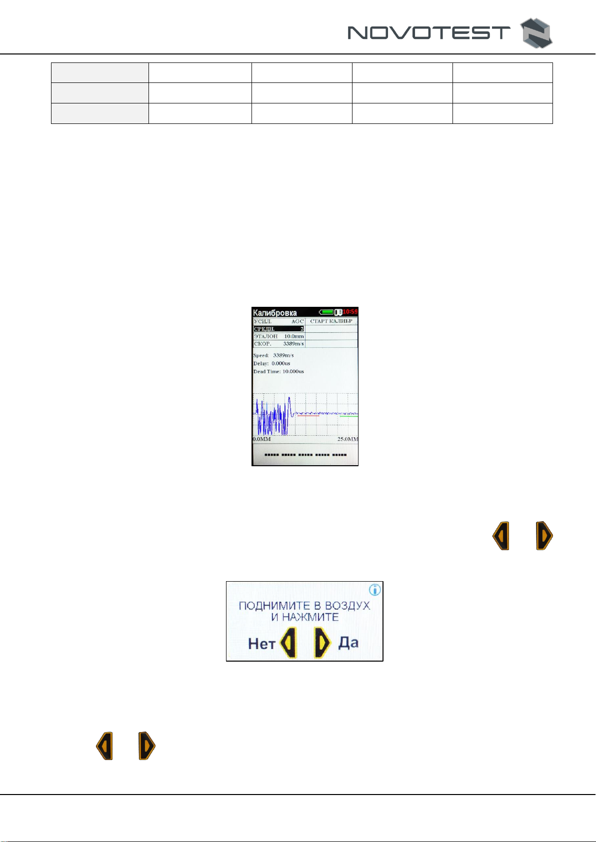
2.3.2.5 Calibration
To calibrate the device, place the EMA transducer on the test object. In “Calibration”mode, set
“AVG.”that can be done by 2, 4, 8, 16, 32, 64 and 128 signals (the averaging can be deactivated if
necessary), set the thickness of the reference sample “REFERENCE” and press “START
CALIBRATION”.
Figure 2.10 –“CALIBRATION” menu
Put the transducer into the air (away from the test object) according to the instruction on the
display “PUT INTO THE AIR” (fig. 2.11), then confirm or reject the action by pressing “ ” or “
”.
Figure 2.11 –“PUT INTO THE AIR”
The device will make a measurement and shows the new instruction on the display “PUT ON
THE SAMPLE” (fig. 2.12), and then operator should confirm or reject the action by pressing the
button “ ” or “ ”.

RDC.ED.UT-3M-EMA.000 OM
Operating manual
EMA Thickness Gauge NOVOTEST UT-3M-EMA
Page. 16
Figure 2.12 –“PUT ON THE SAMPLE”
The device will make a measurement and display the thickness of the reference sample. If the
measured value is different from the reference sample and error is more than (0.01h + 0.05) mm, the
device must be re-calibrated.
2.3.3 “SETTINGS”mode
When “SETTINGS” mode is selected (fig. 2.13), the device will go to the settings of the next
parameters:
“LANGUAGE”: setting the language of the device menu (English and Russian are
available);
“BRIGHTNESS”: change of the display brightness (10%, 20% … 100%);
“COLOR SCHEME”: selectin of the color scheme (01, 02);
“SOUND”: Turning on/off (“ON”, “OFF”);
“TYPE F.”: “Median” filter, “OFF”;
“CLEAR. SD”: Clearing of SD card (switching “OFF”to “ON”), the SD card level is
shown on the bottom part of the display;
“TRANSDUCER”: the selection of the stored transducers;
“MATERIAL”: aluminum, duralumin Д16Т, bronze, tungsten, iron, gold, brass, ЛС-59-1
brass, magnesium, manganese, copper, molybdenum, nickel, tin, lead, silver, steel
20ГСНДМ, ХН77ЕЮР steel, 40ХНМА steel, ХН70ВМТЮ steel, ХН35ВТ steel,
Х15Н15ГС steel, СТ3 steel, chromium, zinc, cast iron, 40х13 steel, user;
“SCALE”: measurement units (mm, μm);
“TIME”: time setting (24h);
“DATE”: setting the date, month, and year DATE/MONTH/YEAR.
Figure 2.13 –“SETTINGS” mode

RDC.ED.UT-3M-EMA.000 OM
Operating manual
EMA Thickness Gauge NOVOTEST UT-3M-EMA
Page. 17
To navigate through «SETTINGS»menu, use “ ” and “ ” buttons, to select the
parameter to be changed, press “ ”, and select the needed value by pressing “ ”, “ ”, “ ”,
“ ” select the needed value that is confirmed by pressing “ ”.
2.3.4 “ARCHIVE”mode
This mode allows seeing all the saved measurement values and, if needed, download the selected
file to continue working with the required settings (fig. 2.14).
Figure 2.14 –“АРХИВ” mode
The saved measurement values are listed and sorted by the date of creation. To handle the saved
files, select the saved file by using “ ” and “ ”, and press “ ”.
2.3.5 “INFORMATION”mode
In this mode, operator can view the product information: battery charge, voltage, consumed
voltage, total operation time, measurement time, serial number, firmware version, and chipboard
version (fig. 2.15).
Figure 2.15 –“INFORMATION” mode
RDC.ED.UT-3M-EMA.000 OM
Operating manual
EMA Thickness Gauge NOVOTEST UT-3M-EMA
Page. 18
2.3.6 Measurement
Before using the device, make sure that the battery is charged sufficiently. The green battery icon
confirms that the battery is charged by 100%. If there is no charge or the charge is low (the red icon),
the battery must be charged by a charger or by connecting the device to a PC.
1. Connect the EMA transducer to the device.
2. Turn the device on by pressing “ ”.
3. Select the operating mode of the thickness gauge by pressing “ ”, and set the needed
parameters.
4. In needed, calibrate the device according to. 2.3.2.5.
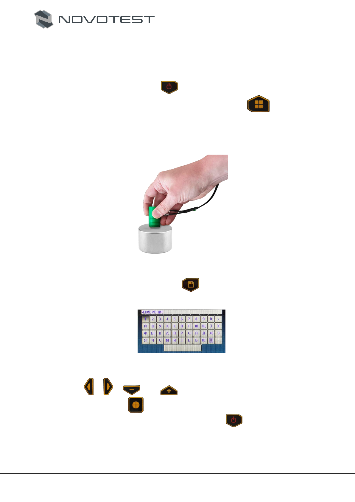
5. Put EMA transducer on the teste object and achieve a stable value on the display (fig.
2.16).
Figure 2.16 –Measurement
6. To save the measurement value, press “ ”. Then, the name of measurement can be set
with a virtual keyboard (fig. 2.17).
Figure 2.17 –The input of the measurement
Use “ ”, “ ”, “ ” and “ ” to navigate through the keyboard, select the needed
symbol by pressing “ ”.
7. To turn the device off, enter the main menu and press “ ”.

RDC.ED.UT-3M-EMA.000 OM
Operating manual
EMA Thickness Gauge NOVOTEST UT-3M-EMA
Page. 19
3 MAINTENANCE OF THE DEVICE AND ITS COMPONENTS
3.1 Safety precautions
After commissioning of the device, it is recommended to inspect it periodically to check the
following:
operability;
compliance with the operating requirements;
battery charge level;
absence of damage to the device components.
When using the charger connected to 220V at 50 Hz, operator should observe the regulations in
“Safety procedure when operating consumer electronic units”.
If the device is not in operation for a long time, the batteries must be disconnected from a power
supply and taken out from the device. Using this, the storage regulations of the battery must be
observed.
The device can be used only be the persons instructed and certified by the ІІ qualification category
by safety engineering using the measuring devices.
3.2 Warranty
The above information about the warranty servicing applies to all the NOVOTEST products.
The manufacturer warrants the compliance of the device with the technical specifications with
compliance with the terms of transportation, storage, and operation, and timely maintenance at least
once a year.
3.2.1 Basic warranty
The device purchased from NOVOTEST or an authorized dealer is covered by the basic warranty
–3 years, subject to the timely maintenance at least once a year.
If any part of the device fails due to the defect of the material or a manufacturer, it shall be
repaired or replaced by the manufacturer, or any authorized dealer of NOVOTEST, regardless of the
transferring of the ownership right to a third party during the warranty period.
The warranty applies from the date of purchase of the device, normally, from the shipment date. If
the device is purchased by an intermediate, the warranty period starts from the date of receipt of the
device by an intermediate.
3.2.2 Extended warranty
There is a special program of extension of the basic warranty from 3 to 5 years. To take advantage
of this program, user needs to pay the certificate with the purchasing. The terms and conditions of the
extended warranty are specified in the certificate.
3.2.3 Warranty for repaired and replaced components
All branded parts of NOVOTEST installed during the warranty repair apply to the NOVOTEST
warranty (up to the end of the warranty period).
The spare parts replaced during the warranty service, shall not be returned to the device owner.
3.2.4 Wearing parts
The parts wearing during the device operation are divided into two main categories. The first part
includes the parts that need to be replaced or adjusted with frequency stipulated by the maintenance
schedule of the device, and the second part includes the wearing parts, which frequency of replacement
or adjustment depends on the conditions of the product operation.

RDC.ED.UT-3M-EMA.000 OM
Operating manual
EMA Thickness Gauge NOVOTEST UT-3M-EMA
Page. 20
3.2.4.1 The parts replaced during the maintenance
The parts listed above have limited service life and need replacement or adjustment with the
periods stipulated by the schedule of the device maintenance. For these parts, the basic warranty
applies before the first part replacement or adjustment. The warranty period for each part cannot
exceed the limitations (by the time of operation of the device or working hours), specified in the
conditions of the basic warranty.
built-in batteries;
gaskets, if they are removed due to accompanying adjustment;
grease and operating liquids.
3.2.4.2 Wearing parts
The parts listed below that have limited service life or need to be replaced (adjusted) due to the
damage. However, these parts are subject basic warranty of NOVOTEST during 12 months:
transducers and their components;
connection cables.
Note: The parts wearing due to friction (such as movable parts of measuring transducers,
ultrasonic piezoelectric transducers, support arm etc.) are not covered by the basic NOVOTEST
warranty, if these parts fail due to wear and tear during the device operation. However, if in the
warranty period these parts fail due to defect of material or workmanship, they shall be repaired or
replaced under the basic warranty.
3.2.5 Owner obligations
The operating manual and registration certificate of the device specifies the information about the
proper operation and maintenance of the device.
Proper operation and maintenance of the device will help avoid costly repairs caused by incorrect
operation, negligence or improper maintenance. Besides, following our recommendations will extend
the service life of the device. Therefore, the device owner should:
If any defect or fault is found, submit the device to NOVOTEST or the authorized dealer
of NOVOTEST for a warranty repair as soon as possible. This can minimize the repair
required for the device.
Use only branded spare parts and couplants of NOVOTEST (with appropriate labels)
during the device maintenance.
Note: The failure to perform the device maintenance in time under the maintenance schedule
deprives of the right to warranty repair or replacement of the faulty parts.
Use only branded spare parts and couplants of NOVOTEST (with appropriate labels).
Make records of the device maintenance in the registration certificate and keep receipts
and bills. If necessary, they will prove that the maintenance was made in time (according
to periodicity specified in the registration certificate), using the recommended spare parts
and couplants. This will help in making warranty claims to defects that might occur due to
a deviation from the device maintenance schedule or the use of unauthorized parts or
materials.
Clean the casing of the device and probe according to recommendations of NOVOTEST.
Fulfill the operation and storage requirements in line with NOVOTEST recommendations.
3.2.6 Warranty obligations
NOVOTEST warranty shall not apply if replacement or adjustment is caused by one of the
following factors:
Table of contents
Other NOVOTEST Test Equipment manuals


