Vivotek FE9182-H User manual

User’s Manual
FE9382-EHV Fixed Dome
Network Camera
5MP • Vandal-proof • 360º Surround View • 20M IR
Smart Stream II • Pixel Calculator • PoE
FE9182-H
Rev. 1.1

VIVOTEK
2 - User's Manual
Table of Contents
Overview...............................................................................................................................................................4
Revision History .............................................................................................................................................. 4
Read Before Use............................................................................................................................................. 5
Package Contents ........................................................................................................................................... 5
Symbols and Statements in this Document..................................................................................................... 5
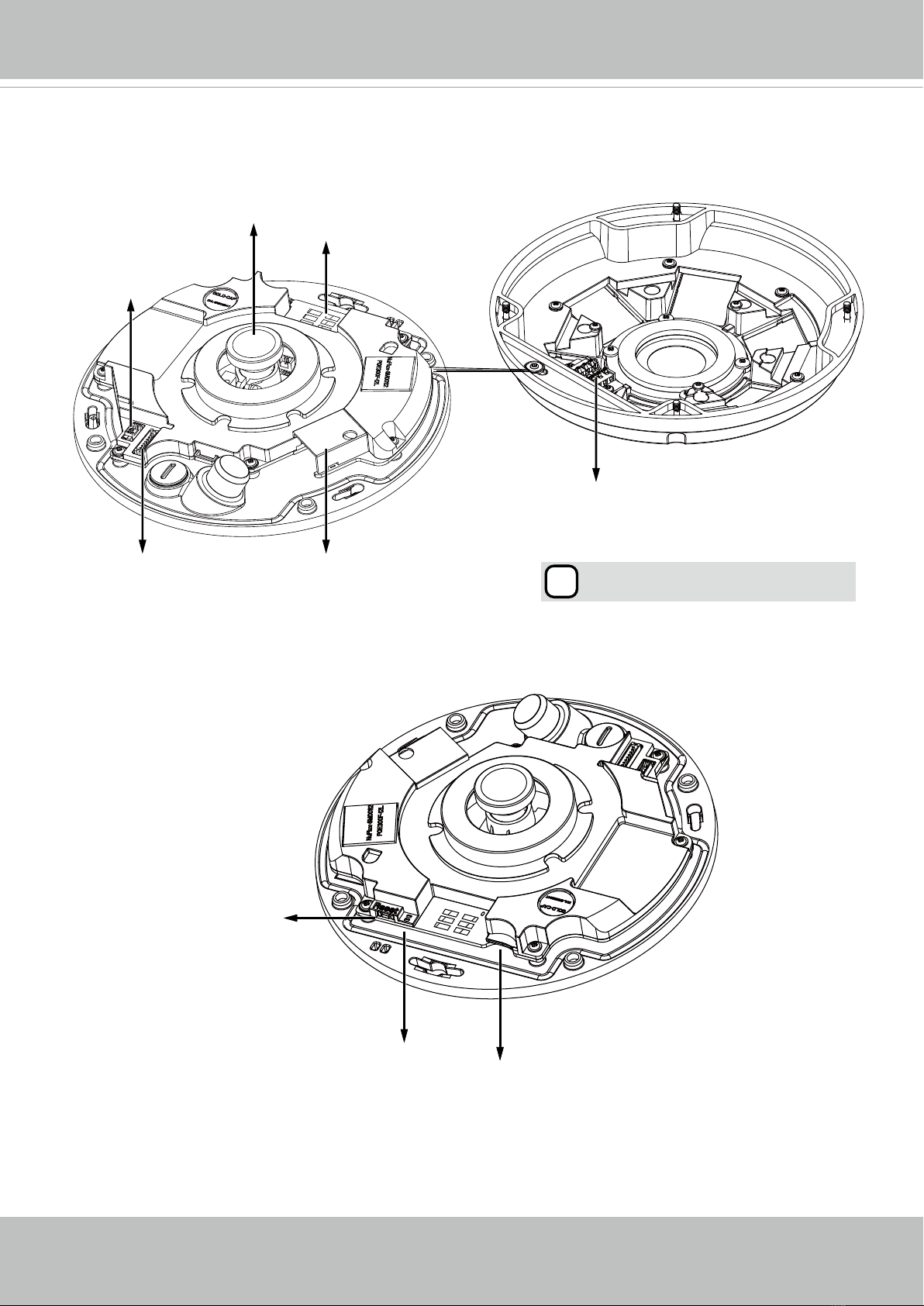
Physical Description - FE9182-H (Indoor Camera) ........................................................................................ 6
Physical Description - FE9382-EHV (Outdoor Camera) ................................................................................. 8
LED Denition - both models........................................................................................................................... 9
Hardware Installation - FE9182-H ................................................................................................................. 10
Hardware Installation - FE9382-EHV ............................................................................................................ 14
Network Deployment .......................................................................................................................................... 24
Setting up the Network Camera over the Internet ......................................................................................... 24
Software Installation ...................................................................................................................................... 27
Ready to Use................................................................................................................................................. 28
Accessing the Network Camera ......................................................................................................................... 29
Using Web Browsers..................................................................................................................................... 29
Using RTSP Players...................................................................................................................................... 32
Using 3GPP-compatible Mobile Devices....................................................................................................... 33
Using VIVOTEK Recording Software ............................................................................................................ 35
Main Page .......................................................................................................................................................... 36
Client Settings .................................................................................................................................................... 47
H.265 / H.264 Media Options ....................................................................................................................... 47
H.265 / H.264 Protocol Options .................................................................................................................... 47
MP4 Saving Options ..................................................................................................................................... 48
Local streaming buffer time .......................................................................................................................... 48
Conguration ......................................................................................................................................................51
System > General settings ............................................................................................................................ 52
System > Homepage layout ......................................................................................................................... 53
System > Logs ..............................................................................................................................................56
System > Parameters ................................................................................................................................... 58
System > Maintenance.................................................................................................................................. 59
Media > Image ............................................................................................................................................63
General settings ...............................................................................................................................................63
Image settings ...................................................................................................................................................68
Exposure .........................................................................................................................................................70
Privacy mask ..................................................................................................................................................73
Pixel Calculator ...............................................................................................................................................74
Media > Video ............................................................................................................................................... 76
Stream settings ..............................................................................................................................................76
Media > Audio................................................................................................................................................ 83

VIVOTEK
User's Manual - 3
Audio Settings .......................................................................................................................................................... 83
Network > General settings.................................................................................................................................. 84
Network > Streaming protocols .......................................................................................................................... 92
Network > QoS (Quality of Service) ................................................................................................................ 100
Network > SNMP (Simple Network Management Protocol) ......................................................102
Security > User Account..................................................................................................................................... 103
Security > HTTPS (Hypertext Transfer Protocol over SSL) ..................................................................... 104
Security > Access List .......................................................................................................................................111
Security > IEEE 802.1x .................................................................................................................................. 114
PTZ > PTZ settings ........................................................................................................................................... 116
PTZ Settings ........................................................................................................................................................... 117
Event > Event settings ....................................................................................................................................... 119
Event ..................................................................................................................................................................... 119
Add server .............................................................................................................................................................. 123
Add media .............................................................................................................................................................. 127
Applications > Motion detection.......................................................................................................................... 133
Applications > DI and DO ................................................................................................................................. 136
Applications > Tampering detection ................................................................................................................... 137
Applications > Audio detection ......................................................................................................................... 138
Applications > Package management - a.k.a., VADP (VIVOTEK Application Development Platform) ............. 140
Recording > Recording settings ........................................................................................................................ 143
Local storage > SD card management............................................................................................................... 148
Local storage > Content management ............................................................................................................... 149
Appendix ................................................................................................................................................................. 152
URL Commands for the Network Camera.......................................................................................................... 152
1. Overview ............................................................................................................................................................. 152
2. Style Convention ................................................................................................................................................ 152
Technical Specications ..................................................................................................................................... 355
Technology License Notice................................................................................................................................. 357
AMR-NB Standard .................................................................................................................................................. 357
Electromagnetic Compatibility (EMC)................................................................................................................. 358

VIVOTEK
4 - User's Manual
Overview
VIVOTEK’s FE9182-H and FE9382-EHV are two unique H.265 sheye xed dome network
cameras, both featuring a detailed 5-Megapixel CMOS sensor that produces superb image clar-
ity. By employing H.265 compression technology and VIVOTEK’s Smart Stream II technology,
these cameras can reduce both bandwidth and storage consumption by up to 80%* while retain-
ing the highest standard of image quality.
Equipped with a fisheye lens for 180° panoramic view (wall mount) or 360° surround view
(ceiling/floor mount) with zero blind spots, the cameras are able to provide coverage of wide,
open areas, such as airports, shopping malls, retail stores, offices and more.
The FE9182-H and the FE9382-EHV are both equipped with a removable IR-cut lter and WDR
Pro technology, empowering the cameras to maintain optimal image quality around the clock
and unparalleled visibility in high-contrast lighting environments. Moreover, the FE9382-EHV is
designed with full EN50155 compliance, vandal-proof IK10-rated, and weather-proof IP66-rated
housing, ensuring that the camera can withstand shock, vibration, humidity, dust, and tempera-
ture uctuations, and maintain stable and reliable video capture during vehicle movement.
* Depending on scene being monitored.
Revision History
Rev. 1.0: Initial release.
Rev. 1.1: Corrected DI/DO pin related description.

VIVOTEK
User's Manual - 5
Read Before Use
The use of surveillance devices may be prohibited by law in your country. The Network Camera is not
only a high-performance web-ready camera but can also be part of a exible surveillance system. It is
the user’s responsibility to ensure that the operation of such devices is legal before installing this unit for
its intended use.
It is important to rst verify that all contents received are complete according to the Package Contents
listed below. Take note of the warnings in the Quick Installation Guide before the Network Camera is
installed; then carefully read and follow the instructions in the Installation chapter to avoid damage due to
faulty assembly and installation. This also ensures the product is used properly as intended.
The Network Camera is a network device and its use should be straightforward for those who have basic
networking knowledge. It is designed for various applications including video sharing, general security/
surveillance, etc. The Configuration chapter suggests ways to best utilize the Network Camera and
ensure proper operations. For creative and professional developers, the URL Commands of the Network
Camera section serves as a helpful reference to customizing existing homepages or integrating with the
current web server.
Package Contents
Symbols and Statements in this Document
i
INFORMATION: provides important messages or advices that might help prevent inconvenient
or problem situations.
NOTE: Notices provide guidance or advices that are related to the functional integrity of the
machine.
Tips: Tips are useful information that helps enhance or facilitae an installation, function, or
process.
WARNING: or IMPORTANT:: These statements indicate situations that can be dangerous or
hazardous to the machine or you.
Electrical Hazard: This statement appears when high voltage electrical hazards might occur
to an operator.
■ FE9382-EHV or FE9182-H
■ Mounting bracket
■ Screws / desiccant bag / double-side tape /
rubber seal plug / rubber washer (some only for
outdoor model)
■ Alignment stickers
■ Quick Installation Guide
■ Mounting plate / star driver (ourdoor model)
■ Power & I/O combo cable (sold separately in US
and Canada)

VIVOTEK
6 - User's Manual
Physical Description - FE9182-H (Indoor Camera)
Inner View
J12
J7
Headers
Contacts
Lens Contacts for IR units
Ethernet 10/100 RJ45 Socket
MicroSD/SDHC/SDXC Card Slot
Reset Button
Status LEDs
Cabling Cutout

VIVOTEK
User's Manual - 7
Outer View
IMPORTANT:
Record the MAC address under the
camera base before installing the camera.
083236
4
Built-in Microphone
Dome Cover
IR lights hidden beneath panel

VIVOTEK
8 - User's Manual
Physical Description - FE9382-EHV (Outdoor Camera)
Inner View
i
Align (B) to (A) when attaching the
dome cover
Header (J7)
Contacts (A)
Lens
Header (J12) Ethernet 10/100 RJ45 Socket
Contacts for IR units (B)
MicroSD/SDHC/SDXC Card Slot
Reset Button
Status LEDs

VIVOTEK
User's Manual - 9
Outer View
IMPORTANT:
Record the MAC address under the
camera base before installing the camera.
Item LED Status Description
1 Steady Red Power on and system booting
Red LED off Powered off
2 Steady Red + blinking Green every 1 sec. (Green
LED on for 1 sec and off for another)
Network heartbeat
Steady Red + Green LED off Network disconnected
3Blinking Red every 0.15 sec. + Blinking Green
every 1 sec. (Red LED on for 0.15 sec. and Green
LED on for 1 sec. and off for another)
Upgrading rmware
4Blinking Red every 0.15 sec. + blinking Green
every 0.15 sec
Restoring defaults
083236
4
LED Denition - both models
Built-in Microphone
IP66-rated Vandal-proof
Dome Cover
IR lights hidden beneath panel

VIVOTEK
10 - User's Manual
First, open the dome cover by pressing the release button. You may squeeze the opposite edge
of the dome cover if the dome cover does not come off easily. Then, follow the steps below to in-
stall the camera to either a ceiling or a wall.
Hardware Installation - FE9182-H
Opening Dome Cover
Release
button
If you plan to route cables from the side of camera,
remove the rubber slide cover from the dome cover.
Slide cover
Connect the supplied power & IO cables if your
switch does not support PoE. Connect the white
header connectors to J12 and J7 on the camera.
Connecting Ethernet Cable
& the Power and IO Cable
Power and IO
cables
J12
J7

VIVOTEK
User's Manual - 11
Connecting Cables
If you need to route cables through the side opening, proceed with the following:
1. Connect the Ethernet and the Power & IO cables. The Ethernet cable is user-supplied.
2.Use an included cable tie to secure the Ethernet and IO cable to the base plate. Insert the ca-
ble tie through the vertical mounting tab located on the edge of the cabling cutout.
3. Make a clearance between cables and the vertical mounting tab. Arrange the cables neatly to
avoid getting in the way when the dome cover is attached.
4.Cut the extra length from the cable tie.
If you route cables through a drill hole
on a wall/ceiling, simply route cables
through the cabling cutout.
Mounting Positions
Refer to the diagram on the right for the
mounting hole positions and the dimen-
sions of the base plate.
Make a clearance
between cables and the verti-
cal tab
Ethernet
Power & IO Cable
n144
n141.22
B
D
4.3
40°
10°
38°
14°
160

VIVOTEK
12 - User's Manual
Ceiling or Wall Mount
1. Attach the supplied alignment sticker for the camera base to the a ceiling or wall.
2.Using the circles on the sticker, drill pilot holes into the ceiling. Then hammer the supplied
plastic anchors into the holes.
3.(Optional) Drill a cable hole on the ceiling/wall, and feed the cables through the hole.
4.Secure the camera base to the ceiling/wall with the supplied screws.
Arrange the cables neatly to avoid getting in the way when the dome cover is attached.
IMPORTANT:
D
r
i
l
l
h
o
l
e
D
r
i
l
l
h
o
l
e
D
r
i
l
l
h
o
l
e
D
r
i
l
l
h
o
l
e
D
r
i
l
l
h
o
l
e
D
r
i
l
l
h
o
l
e
12
3
4

VIVOTEK
User's Manual - 13
You may also install the camera to a U.S. standard 4 in. junction
box. You can align the camera’s curved slots with the mounting
holes on a junction box. Use diagonal mounting positions on the
camera to match those on a junction box.
Install the plastic dome cover by aligning the snap-
t tabs on the dome cover with the slotted tabs on the
camera base. Install the dome cover by pressing it even-
ly to the camera base.
Make sure the dome cover and the base plate are ush-
aligned before pressing down. The dome cover is se-
cured using a snap-t mechanism.
NOTE:
Attach the Dome Cover
Snap-t tabs
Slotted tabs
Dome cover

VIVOTEK
14 - User's Manual
Hardware Installation - FE9382-EHV
Opening Dome Cover
Rubber Stopper on the hole
for Power & IO Cables
Tamper-proof Screw
Rubber Seal Plug on the
hole for RJ45 Ethernet
Cable
Remove the stoppers and route cables through
the openings.
First, use the supplied screwdriver to loosen the four screws and detach the dome cover from the
camera base. Then, follow the steps below to install the camera to either a ceiling or a wall.
Hardware Reset
The reset button is used to reset the system or restore the factory default settings. Sometimes
resetting the system can return the camera to normal operation. If the system problems remain
after reset, press the reset button longer to restore the factory settings and install again.
Reset: Press and release the recessed reset button with a straightened paper clip. Wait for the
Network Camera to reboot.
Restore: Press and hold the recessed reset button for at least several seconds to restore. Note
that all settings will be restored to factory defaults.
Micro SD/SDHC/SDXC Card Capacity
This network camera is compliant with Micro SD/SDHC/SDXC 32GB, 64GB, and other
preceding standard SD cards preferrably with class 6 speed.

VIVOTEK
User's Manual - 15
RJ45 Cable Dimension (unit: mm)
Assembly Steps
1. Drill a hole on the rubber seal plug and
insert an Ethernet cable through the
opening.
2. Strip part of the sheath from the Ether-
net cable.
Recommended cable gauge: 5 to 8mm
Connecting RJ45 Ethernet Cable
Connecting DC Power Cable
1. Add the supplied rubber washer to the cable
as shown in the picture.
2. Feed the cable from the bottom of the cam-
era and tighten the plastic base for water-
proong.
1
2
3. You will need an RJ45 crimping tool to
attach the Ethernet wires to a connec-
tor. When done, connect the cable to
the camera’s Ethernet RJ45 socket.
o
O
g
B
b
G
br
BR
1
2
3
4
5
6
7
8
3
4.Feed the Ethernet cable from the bottom of the
camera and through the hole. Attach the rubber
seal plug for water proong.
o: white/orange stripe
O: orange solid
g: white/green stripe
B: blue solid
b: white/blue stripe
G: green solid
br: white/brown stripe
BR: brown solid
Connect the supplied power & IO cables if your
switch does not support PoE.
NOTE:
Rubber Seal Plug
1
2
4

VIVOTEK
16 - User's Manual
Mounting Positions
Refer to the diagram on the right for the mounting hole positions and the dimensions of the base
plate.
Camera Base Plate Mounting
Positions
Camera Mounting Plate Mounting Positions
144
26°
8°
8°
8°
26°
8°
160.35
3.45
11
59.97
141.22
M3X0.5 TH 30°
13°
13°
47°
47°
13°
121.23
161.99
4.3

VIVOTEK
User's Manual - 17
Ceiling/Wall Mount without Mounting Plate
(Choose this mounting type if you want to feed the cables form the bottom of the camera)
1. Attach the supplied alignment sticker for camera base to the ceiling/wall.
2. Using the three circles on the sticker, drill three pilot holes into the ceiling. Then hammer the
three supplied plastic anchors into the holes.
3. Drill a cable hole on the ceiling/wall, and feed the cables through the hole.
4. Connect the Ethernet cable to the socket.
5. Connect the two white header connectors to the J12 and J7 connectors.
6. Secure the camera base to the ceiling/wall with three supplied screws.
7. You will nd a dessicant bag attached to the camera. Replace the dessicant bag included in
the camera with the one shipped within the accessory bag.
8. Attach the dome cover.
9. Secure the four screws with the supplied stardriver. Make sure all camera parts are securely
installed.
Arrange the cables neatly to avoid getting in the way when the dome cover is attached.
IMPORTANT:
Header (J7)
Header (J12)
126
3
8
9
45

VIVOTEK
18 - User's Manual
Ceiling/Wall Mount with Mounting Plate
(Choose this mounting type if you would like to feed the cables form the side)
1. Attach the supplied alignment sticker for the supplied mounting plate to the ceiling/wall.
2.Using the three circles on the sticker, drill three holes into the ceiling. Then hammer the three
supplied plastic anchors into the holes.
3.Arrange and feed the cables through the side of the mounting plate.
4.Secure the mounting plate to the ceiling/wall with three supplied screws.
5.Connect the Ethernet cable to the socket.
6.Connect two white headers to the J12 and J7 connectors.
7. Attach the camera base to the mounting plate and turn counter-clockwise as shown below.
Then secure the supplied screws to x the camera base.
8. You will nd a desiccant bag attached to the camera. Replace the desiccant bag with the
one shipped within the accessory bag.
9.Attach the dome cover.
10. Secure the four screws with the supplied stardriver. Make sure all camera parts are se-
curely installed.
1
2
3
4
7
9
10

VIVOTEK
User's Manual - 19
You may also use the diagonal holes on the mounting plate,
marked as A, B, or C, to install the camera to a U.S. standard
4 in. junction box.
Please replace the desiccant bag with a new one every time you open the dome cover.

VIVOTEK
20 - User's Manual
Install the "Installation Wizard 2" software utility from your software CD.
The program will search for VIVOTEK Video Receivers, Video Servers or Network Cameras on
the same LAN.
Double-click on the camera's MAC address to open a browser management session with the
camera.
With a live view is displayed on your laptop, adjust the zoom and focus to obtain an optimal
image. Check the live view to ensure the image is in focus.
1. Connect RJ45 Ethernet cable to a switch.
2. Connect the power cable from the Network Camera to a power outlet.
3. If you have external devices such as sensors and alarms, make the connection from the
general I/O terminal block.
General Connection (without PoE)
POWER C
OLLIS
ION
LINK
RECEIVE
PARTITION
12345
+5V
DO
D1
GND
1
2
3
General I/O Terminal Block
Power Cord Socket (Black)
Microphone In (Pink)
Audio Out (Green)
+5V : Power, 5V DC
DO : Digital Output
DI : Digital Input
GND : Ground
IMPORTANT:
If DC power is preferred, it should comply with: O/P: 12VDC, 2A min., L.P.S. per IEC 60950-1.
Other manuals for FE9182-H
1
This manual suits for next models
1
Table of contents
Other Vivotek Dome Camera manuals