ViziT VIZIT-M440CM User manual

VIZIT-M440C
VIZIT-M440C
M
M VIZITis a colour monitor with a built-in memory for 64 images. The monitor is intended for use in video
doorphones.
1.
.
5.
6.
.
10.
11.
12.
Handset
2 DOOR OPEN button
3. Increase value / view next image button
4. Decrease value / view previous image button
button
AWAY mode button
7. AWAY mode LED indicator
8. Capture image button
9 Switch to extra camera button
MONITOR button
Power LED
Screen
MENU
Figure Appearance and controls layout1-
1
7
3
9
2
4
5
10
12
11
6
8
Screw 3.5 25- х Concrete Insert 6х30
x 3 x3
Fasteners
Operating Instruction
x1
- 440
Monitor
VIZIT M CM
x1
PARTS LIST

SAFETY INSTRUCTIONS
CAUTION 27V
FEATURES
!The Monitor does not contain voltage above .
Do not perform any connections or repair when the power is on.
Colour 3 5
Non-volatile memory for 64 images
Non-volatile clock
Operation with two doorstations and extra camera (commutator BKM-440 required)
Operation with one doorstation, door bell button and extra camera (commutator BKM-440 not required)
Calls from doorstation and door bell button
Duplex intercom
Remote door unlocking with the button
Door zone video monitoring
Activation of individual / storey doorstation by subscriber (duplex intercom and video monitoring)
On-screen menu
4 ring tones, individual ring tone for each doorstation and door bell button.
3 ring volume levels
Individual image brightness, contrast and saturation for each doorstation and extra camera
LED indication of operating modes
Choose the position for monitor Recommended altitude is 150 cm from the floor to the monitor center
v
v
v
v
v
v
v
v
v
v
v
v
v
v
v
. ” TFT LCD
..
Take care not to spill any liquids or chemically active substances on the product.
Unplug the power supply unit before cleaning the monitor. Clean by wiping with dry soft cloth. Do not use any liquid cleaners,
aerosol cleaners or abrasive agents.
Do not attempt to service the product by yourself. Please refer all services to qualified service personnel.
INSTALLATION
Figure Rear view2-
1
3
5
2
6
4
4
1
3
2
Connecting terminals
DC IN to connect power supply
unit SA03010029
Recess for cables
4
6
5
Inlets for cables
Fixing lugs
Socket for handset jack

The monitor terminals and their destination are given below
See Fig. 4 - 7 for the of the monitor and other doorphone units.
Acceptable cross-sections of wires to connect the monitor to the power supply unit, doorstation / control unit
(Fig. 4 - 5) are given in the doorstation / control unit operating instructions.
Acceptable cross-sections of wires to connect the monitor to the commutator (Fig. 6 - 7) are given in
the commutator BKM-440 operating instruction.
If the monitor operates together with the commutator , a door bell button connection is not available
:
.
examples of wiring diagrams
BKM-440
Note
BKM-440
.
Connect the wires to the terminals of your
monitor as shown in Fig. 4-7.
Match the monitor’s fixing lugs with the screws
in the wall, and hook the monitor on the
screws.
Figure Installation order3-
2
3
Connect the handset to
the monitor.
1
3
2
85
57
85
1
Make 3 holes in the wall.
Refer to page 25 for Mounting Pattern.
Drive in concrete inserts and screws
supplied with your monitor.
3
2
1
Terminal
LN +
LN -
GND
VI1
+E
DATA DATA exchange between monitor and commutator BKM-440
Supply voltage for monitor
VIDEO IN from doorstation built-in camera
Ground
Intercom line between monitor and commutator /doorstation
Destination
Ec1
Ec2
GND
VI2 VIDEO IN from cameraextra
Ground
Supply voltage for cameraextra
Supply voltage for doorstation built-in camera

EXAMPLES OF WIRING DIAGRAMS
Figure 5 Monitor with individual / storey
doorstation and extra camera
-VIZIT-M440CM
-18
+18
+12
-12
POWER SUPPLY
BPD18/12-1-1
V
1A
50
ELECTROMECHANICAL
LOCK R 10 OHM)(
LINE
GND
+E
VO
Ec
LC
BVD 410CBL-
LN-
GND
LN+
VI1
+E
DATA
Ec1
Ec2
GND
VI2
MONITOR
VIZIT M CM- 440
VO
Ec
GND
Extra Camera
12 V max, 0.3 А
Door bell
button
INDIVIDUAL / STOREY
DOORSTATION
Colour
Figure Monitor with
doorstation and extra camera
M4 - VIZIT-M440C multi-apartment
To next commutators
To other apartments
82-Ohm resistor should be
connected between the VO
and VG terminals of the last
commutator in the circuit
- 440
MONITOR
VIZIT M CM
Extra Camera
12 V max, 0.3 А
To doorstation / control unit
Door bell
button
Note. Door bell button can be installed near your apartment door, and
connected to the GND and DATA terminals of the monitor
Commutator
BK-4MV
or BK-4V()
VO
Ec
GND
LN-
GND
LN+
VI1
+E
DATA
Ec1
Ec2
GND
VI2
VO
VG
VG
18
+18
V1
FA
LN
VG
V2
FB
LN
VG
V3
FC
LN
VG
V4
FD
LN
VG
GND
LINE
SEL
Ek VI
18В, 0.5А
Power Supply SA03010029
GND +E
DC IN

Figure Monitor as the main device with
doorstation, individual / storey doorstation and extra camera
M6 - ( )VIZIT-M440C multi-apartment
HS+
COMMUTATOR
BKM-440
HS-
LN1-
GND
V 2
+E
L1N+
LN2-
V 1
LN2+
Ec1
Ec2
+E
GND
LN-
GND
LN+
+E
DATA
VO1
HS/MON
EQUIV
AB
C
VO2
GND
VO
Ec
GND
Extra Handset
INDIVIDUAL / STOREY
DOORSTATION
+
LN
GND
+E
Ec
LC
-BVD 406CB
VO
VG
To next commutators
To other apartments
VO
VG
VG
18
+18
V1
FA
LN
VG
V2
FB
LN
VG
V3
FC
LN
VG
V4
FD
LN
VG
GND
LINE
SEL
Ek VI
82-Ohm resistor should be connected
between the VO and VG terminals
of the last commutator in the circuit
COMMUTATOR
BK-4MV
or BK-4V()
To
doorstation / control unit
multi-apartment
18
+18
+12
12
POWER SUPPLY
BPD18/12-1-1
Main Monitor
•
•
Individual / storey doorstation activation
Switching of video channels
Intercom priority over Extra Handset•
Extra Camera
12 V max, 0.3 А
V
1A
50
ELECTROMECHANICAL
LOCK R 10 OHM)(
LN-
GND
LN+
VI1
+E
DATA
Ec1
Ec2
GND
VI2
- 440
MONITOR
VIZIT M CM

Figure Monitor as extra device
with two individual / storey doorstations
7 - MVIZIT-M440C ()
BVD-401СВ
LN
LС
+E
Ec
VO
GND
LN
GND
+E
Ec
LC
BVD 406CB-
VO
VG
- 460
MONITOR
TERMINAL
VIZIT MT CM
18
+18
+12
12
POWER SUPPLY
BPD18/12-1-1
HS+
COMMUTATOR
BKM-440
HS-
LN1-
GND
V 2
+E
L1N+
LN2-
V 1
LN2+
Ec1
Ec2
+E
GND
LN-
GND
LN+
+E
DATA
VO1
HS/MON
EQUIV
AB
C
VO2
GND
18
+18
+12
12
POWER SUPPLY
BPD18/12-1-1
Extra Monitor
Main Monitor
INDIVIDUAL / STOREY
DOORSTATION
INDIVIDUAL / STOREY
DOORSTATION
V
1A
50
ELECTROMECHANICAL
LOCK R 10 OHM)(
ELECTROMECHANICAL
LOCK R 10 OHM)(
V
1A
50
LN-
GND
LN+
VI1
+E
DATA
Ec1
Ec2
GND
VI2
•
•
Individual / storey doorstation
activation - N/A
Switching of video channels - N/A
LN
GND
LN+
+E
DATA
VI
AWAY RC
ME U
•
•
Individual / storey doorstation
activation
Switching of video channels
Intercom priority over Extra
Monitor
•
- 440
MONITOR
VIZIT M CM

SETUP
Turn on the power supply unit or commutator BKM-440.
Note.
Select a device (doorstation, or extra outdoor camera and door bell button) to make settings
MENU
MENU
MENU
MENU
Select a ring tone, set its volume*, adjust brightness, contrast and saturation of colour image. Set MENU
language, time and date, if needed.
To select a setting
To set a ring tone RING SOUND MENU
MENU RING
SOUND
To set a ring tone volume RING VOLUME MENU
MENU
RING VOLUME
To adjust image brightness, contrast and saturation MENU
MENU
Note.
LANGUAGE MENU
CLOCK MENU
MENU
MENU
OK MENU
CANCEL MENU
To quit menu OK MENU
Before turning the power on, make sure that there is no misconnection or risk of short circuit.
The monitor’s Power LED (see Fig.1) illuminates with green light.
The Power LED may not illuminate at once, after turning the power on; the delay may take up to 7 seconds.
If in 7 seconds the Power LED is still dim, then the monitor is in the sleep mode (calls are ignored, and all buttons
except for are disabled). To switch the monitor on, press the button.
When the monitor is in the stand-by mode (its screen is black), press one of the following combinations of buttons:
1. > (select doorstation)
1. > > (select second doorstation)
1. > > (select extra outdoor camera and door bell button)
After you press the button, the main page of on-screen menu appears.
*Ring tone volume remains the same for both doorstations and door bell button, i.e. if you change ring tone volume for
one device, it will automatically change for the rest of connected devices.
, move the cursor bar up and down by pressing the and buttons.
(one of four), select ‘ ’ in the menu. Press the button, and the cursor bar jumps
to the current setting. Press or to select a new ring tone. Every time you press either or , the selected ring
tone sounds. After you have chosen the ring tone, press the button. The cursor bar jumps back to ‘
’.
(3 levels), select ‘ ’ in the menu. Press the button, and the cursor bar
jumps to the current setting. Press to decrease or to increase volume. Every time you press either or , the
test sound rings to present the volume level. After you have chosen the volume level, press the button. The cursor
bar jumps back to ‘ ’.
, select a corresponding line in the menu. Press the button,
and video image appears in the screen. In the lower part of the screen an adjustment bar is displayed. Set a preferred value
with the or buttons and press the button to return back to the main page.
If the buttons and are not pushed within about 15 seconds, the monitor automatically quits menu.
To change menu language, select ‘ ’ and press the button.
To set date and time, select ‘ ’ in the menu and press the button. The menu goes to the next page:
Select a required line with or and press the button, the cursor bar jumps to the current setting. Change the
settings with or and press the button. The cursor bar returns to the menu line.
To save settings and return to the main page of the menu, select ‘ ’ and press the button.
To return to the main page without saving setting, select ‘ ’ and press .
, select ‘ ’ and press the button.
§
§
§
MENU
OK
Ring volume
Brightness
Contrast
Color
Clock
Ring sound 1
3
08
09
10
Language Eng
Cursor bar
Current
settings
Clock
Cancel
Year
Month
Date
Hours
Minutes
OK
11
10
21
10
30
Current
Settings

Note. extra monitor
FUNCTIONAL CHECK AND OPERATION ORDER
Note.
Special notes on operation with BKM-440
main extra
main intercom priority extra main monitor’s
extra extra
main
Image capture
To capture visitor’s image during intercom
To set the monitor on automatic image capture
Note.
Viewing captured images
-01
-02
Note.
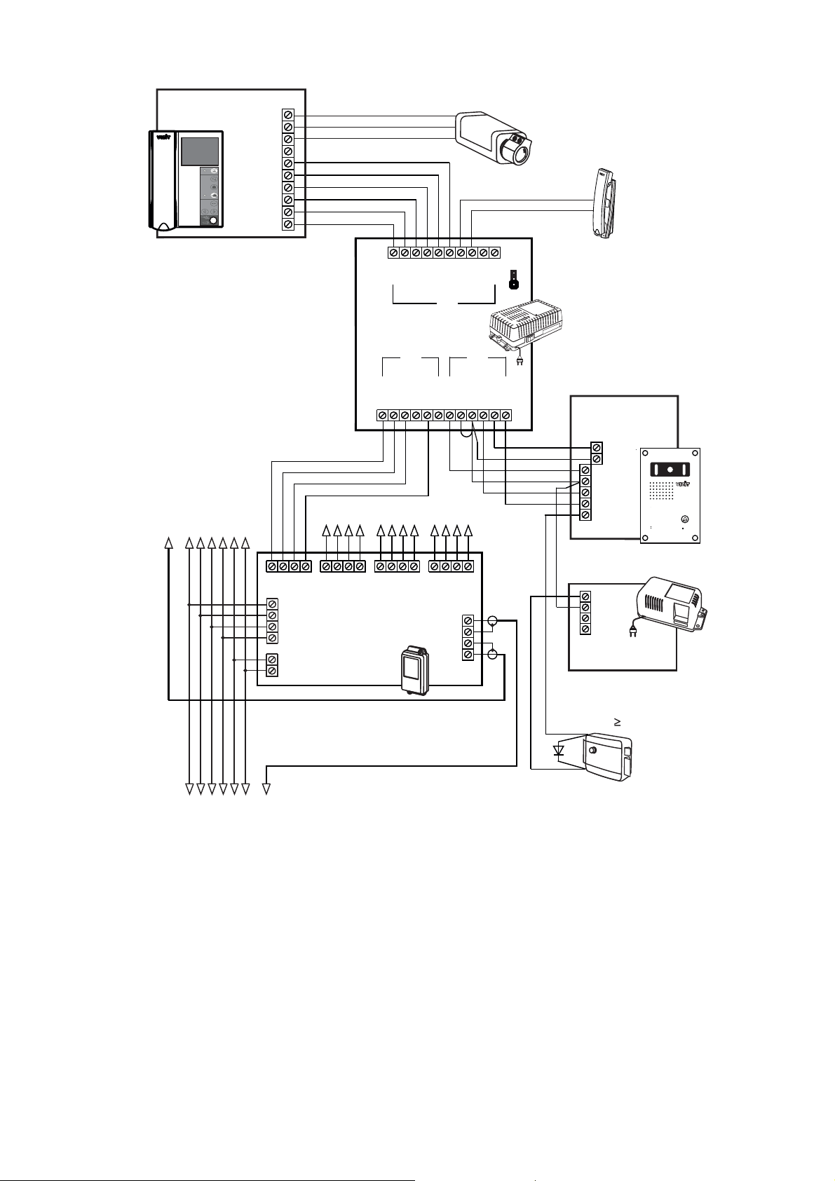
If your monitor is connected to Commutator BKM-440 as an (see Fig. 7), then individual settings for
the first and second doorstation are not available, settings will be the same for both doorstations. To perform settings, make
a call to the monitor from either connected doorstation.
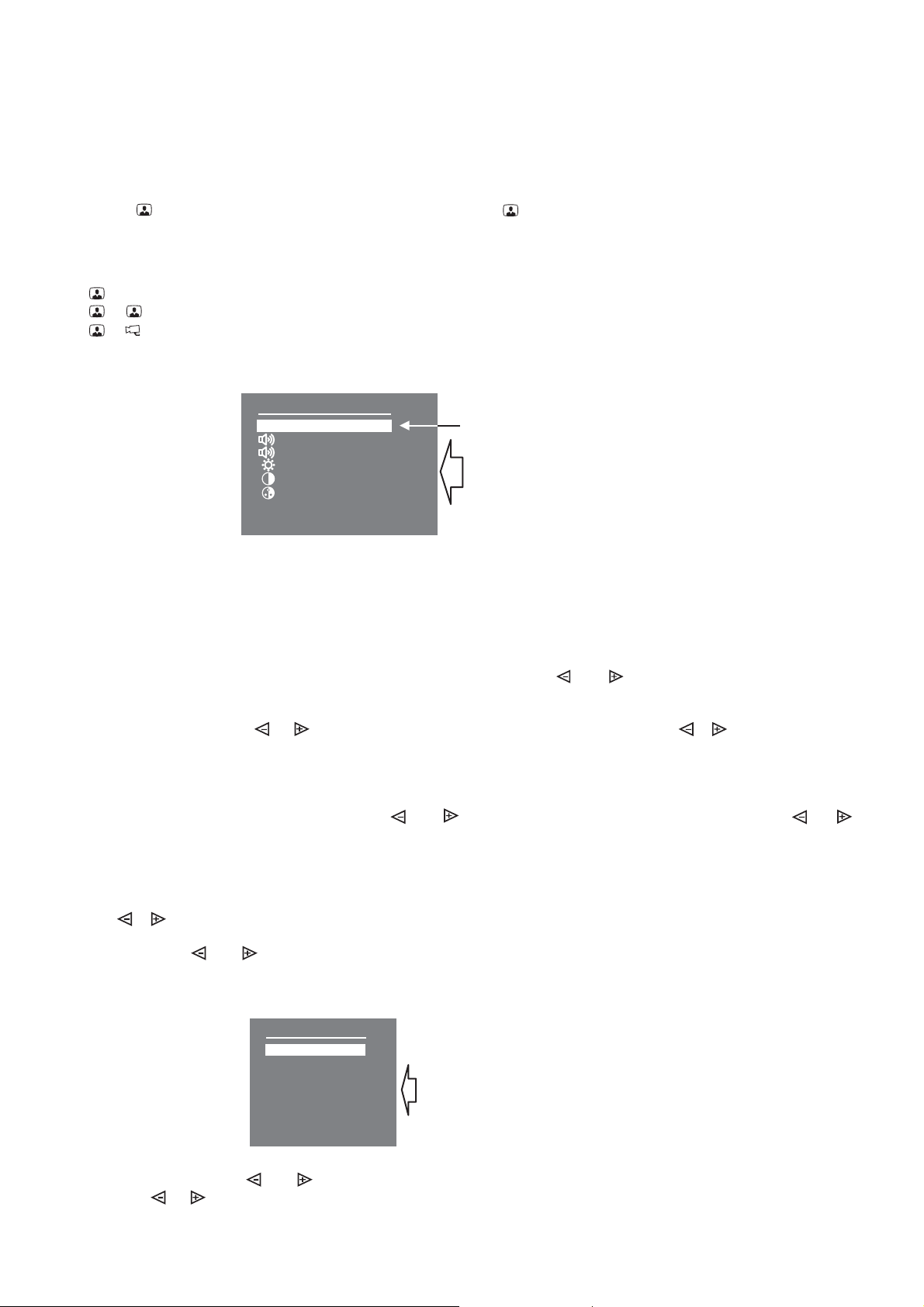
Then select a ring tone, set its volume, adjust brightness, contrast and saturation as described above.
When a call is made from the doorstation, the monitor rings. Image from the doorstation camera appears on the screen.
Pick up the handset and check duplex intercom. During intercom, press to view image from the extra camera (see Fig. 4,
5, 6), if needed. Press again to switch back to the image from the doorstation camera.
To release the door lock, press and hold for 1 second (until a beep). The door is unlocked now. After you release the
button, intercom is still available. Hang up the handset. The screen shuts off, the monitor goes to the Stand-By mode.
You can unlock the door without picking up the handset. When called, just press and hold until the beep. The
door is unlocked now. After you release , the monitor goes to the Stand-By mode.
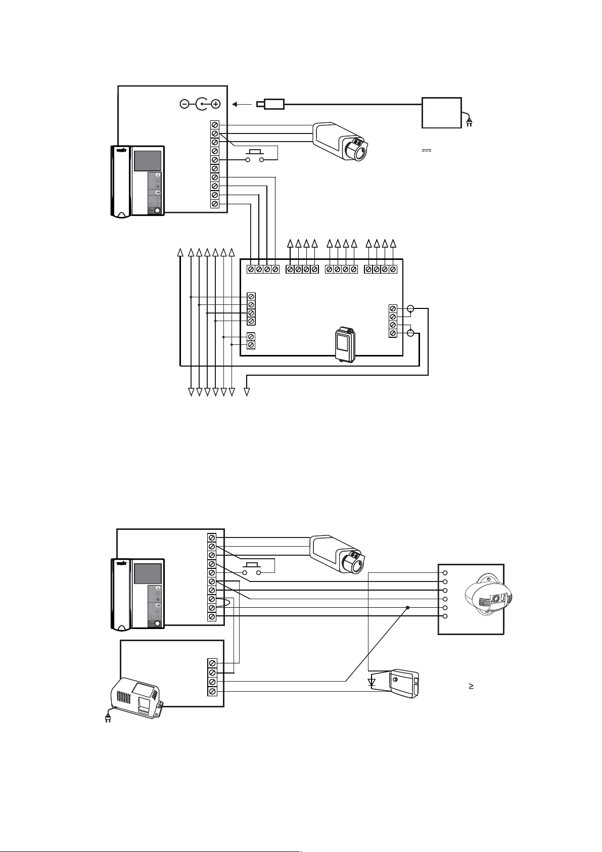
To activate the individual / storey doorstation (i.e. start intercom and video monitoring on your initiative, see Fig. 5), pick
up the handset. Image appears on the screen, intercom is available. You can press to view image from the extra
camera, if needed. Press again to switch back to the image from the doorstation camera.
At pressing the door bell button, the monitor rings, image from the extra camera appears on the screen (see Fig. 4, 5).
To engage the sleep mode, press and hold until the Power LED turns off.
The monitor can be connected to the BKM-440 either as the (see Fig. 6) or the monitor (see Fig. 7). The
monitor has an over any device, i.e. when you pick up the handset, the
monitor (or extra apartment handset) is disengaged. The monitor cannot activate the individual / storey
doorstation.
To view the door zone in front of main entrance doorstation (see Fig. 6), press on the monitor, or pick up its
handset. To switch to viewing the door zone in front of individual / storey doorstation, press again. To start intercom
with the individual / storey doorstation, pick up the handset.
, press the button on your monitor, when image from the camera is on the
screen.
, press the button, when the monitor is on stand-by.
The LED indicator for AWAY mode starts to illuminate.
The monitor captures an image in 3 seconds after a call starts. The LED indicator blinks if there are new images in the
monitor’s memory.
To quit automatic image capture mode, press the button, when the monitor is on stand-by. The LED indicator for AWAY
mode goes out.
The monitor’s memory is capable to store 64 images. If the memory is full, a new image forces out the oldest one from
the archive.
To start viewing captured images, press either or . The screen switches on and shows the newest captured image. In
the lower part of the screen there are time, date and number of the image displayed. The newest image has number . A
previous image has number , and so on.
Press either or to view previous or next image respectively.
To quit viewing press .
The monitor automatically quits viewing:
- in 40 seconds, if you do not push any button;
- when being called from the doorstation.
Captured images are always B/W disregarding the type of camera (either B/W or colour).

SPECIFICATIONS
3.5” (89mm)
Ohm
V p-p
VDC
W
14 mm
0.6 kg
OPERATING CONDITIONS
Screen
Colour system
Video IN
impedance
voltage
Operating voltage
Power consumption max.
Dimensions (W)x(H)x(D) x x
Weight
TFT LCD
PAL
470
1…1.8
15…27
3
0 183 48
:
-
-
Ambient temperature range + to +
Relative humidity of air up to at +
5°C 40°C
93% 25°C
Other manuals for VIZIT-M440CM
1
Table of contents
Other ViziT Monitor manuals