VLTG TV-N380BEAM User manual
1
BEAM 380W
TV-N380BEAM
User manual
Please read this instruction carefully

2
before use
广州蔚来灯光科技有限公司
Contents
1. Safety Instruction …………………………………………………………3
2. Technical Specifications ………………………………………………4
3. Description …………………………………………………………………7
3.1 Control Panel ……………………………………………………7
4. lamp ………………………………………………………………………8
4.1 lamp bulb ………………………………………………………8
5. Fixture settings ……………………………………………………………8
5.1 Main Function …………………………………………………8
5.2 Error message …………………………………………………11
6. Universal DMX controller control …………………………………………12
6.1 Connection ……………………………………………………12
6.2 Channel settings ………………………………………………13
6.3 Address code setting …………………………………………13
6.4 DMX 512 channel ……………………………………………13
7. Fault Handling ………………………………………………………………18
8. Maintenance and cleaning …………………………………………………19

3
Please read this manual carefully. It contains important information about installation,
use and maintenance.
Warning
1. Safety Instruction
Please read this instruction carefully before using this product.。
Please keep this manual as a reference for future consultation,If you sell this product to other
users, please make sure they also get this manual.
Please use it correctly on the basis of full understanding of the content.
Notice:
The equipment is packed in good condition when leaving the factory. Please operate it according
to the user's manual. The machine failure caused by human factors is not covered by the warranty.
Before using the product, please open it and check carefully,to ensure that there is no damage
caused by transportation.
This fixture is only suitable for indoor dry places.
The installation and operation of the fixture,should be carried out by professionals.
Do not let children operate the fixture.
Use secure ropes when fixing the device, and hold the bottom at the same time when moving the fixture.
The equipment must be installed in a well-ventilated place, at least 50 cm away
from the adjacent surface.
Make sure the ventilation holes are clear to avoid overheating when the fixture is running.
Before operation, make sure that the power supply voltage matches the power supply voltage required
by the fixture.
Please ground the conductor to prevent electric shock.
Ambient temperature: Do not operate the fixture below -25°C or above 45°C.
It is forbidden to connect the fixture directly to the dimming equipment.
Do not place combustible materials within 1 meter of the fixture When it is running, , to avoid fire hazard.
Please carefully check whether the power cable is damaged before turning on the
fixture, and replace it immediately if there is any damage.
The surface temperature of the fixture can reach 55℃during operation, please do not touch it
with bare hands.
Avoid operating in dirty and dusty environments, and clean and maintain the fixture regularly.
It is forbidden to touch the wire when the fixture is running to prevent electric shock.
Avoid entanglement of the power cable and other wires
The distance between the fixture and the illuminated surface should be greater than 15M。
Disconnect the power supply before replacing the fuse or bulb.

4
Use the same model when replacing fuses or bulb.
There is a serious operation failure, please stop using it immediately。
Do not turn on the fixture repeatedly.
Please replace the lamp housing, lens or ultraviolet filter when there is obvious damage.
There are no available parts inside the fixture, please do not open thefixture housing without
permission
Do not operate the machine by yourself. Operation by non-professionals will cause damage to
the device or malfunctions.If you need maintenance, please contact the nearest authorized
service center.
Please turn off the power when the fixture is not used for a long time or maintenance.
When shipping again, please use the original packaging material.
To avoid fire or electric shock, do not expose the fixture to rain or wet areas.
There is a danger of explosion due to high temperature bulbs. Please do not turn on the lamp within 15
minutes after power off.
Please replace the bulb in time if the bulb is damaged, deformed by heat or exceeds the service life
Do not stare at the fixture directly during operation
The bulb will be very hot when the fixture is running. Do not touch the bulb with bare hands.
The plug must be grounded when the fixture is in operation.
Don’t operate the fixture when the bulb has no protective cover or the housing is damaged
2. Technical Specifications
Power supply:
100~240V,50/60Hz
Power rated:
530W
Bulb:
SIRIUS HRI ® 371W (Lamp rated life:1500H)
Color temperature:
7650K

5
Power off display function:
DMX address and other menu function can be set when power is off
Automatic charging when power on
No need to change the battery
Optical System:
Efficient optical system
Powerful light output
High quality optical lens
Movement:
Horizontal:540°
Vertical:270°
The speed of horizontal/vertical movement can be adjusted.
Automatically horizontal/vertical correction.
Optocoupler positioning function for easy initial position correction and maintenance
Vertical locking function to prevent damage to lamp during transportation
Dimming/strobe:
0%~100% smooth dimming, multiple
speed strobe effect
Color wheel:
Color wheel:2 color wheel,each has 11 color+white. Two-way rainbow effect
Fixed Gobo Wheel:
Gobo Wheel:1 fixed gobo wheel, 14 gobo+white. Magnetic positioning function for easy initial.
Prism:
Prism1: 48 prisms that can be rotated and overlapped in two-way
Prism2: T prism(symmetrical) that can be rotated and over lapped in two-way
Prism3: 24 honeycomb prism that can be rotated and overlapped in two-way
Prism4: 16 prism that can be rotated and overlapped in two-way
Prism5: 8 prism that can be rotated and overlapped in two-way
Prism6:Fog
6
Focus:
Electronic linear focusing
Heat dissipation:
Fan cooling
General controller:
DMX 512 controller
DMX signal input/output: 3-pin XLR signal
line interface
N.W:
22.4Kg
G.W(Carton):
26.5Kg
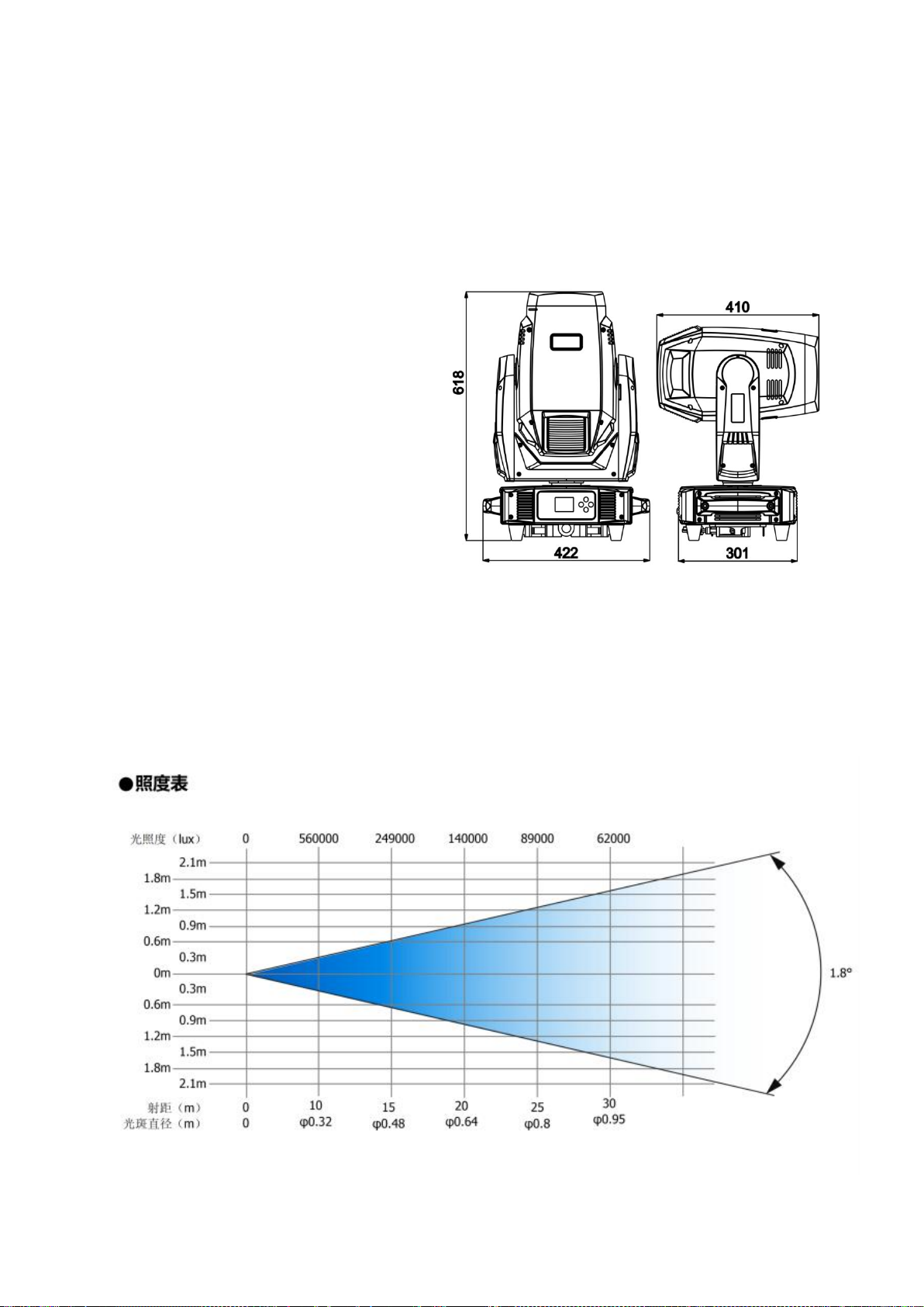
Dimension:
618× 422 × 301mm
Product Illumination Chart

7
3. Description
3.1 Control Panel
Front panel Back panel
1.
Display screen:Display various function menus;
2.
Button:
MENU
Return
DOWN
To the next option
UP
Go to previous option
ENTER
Enter menu selection function\Confirm selected
function
3.
Phoenix Plug:For DMX transfer;
4.
Fuse (T 8A):
Overcurrent protection;
5.
DMX Input:
For DMX 512 connection, use 3-pin XLR signal cable to connect the fixture and DMX console, and input
DMX signal;
6.
DMX Output:
Used for DMX 512 connection, use 3-core XLR signal cable to connect to the next machine;
7.
Power Switch:
Turn the power on or off。
8.
Power Cable:
Connect to power supply;
8
4. Lamp Bulb
4.1 lamp bulb
SIRIUS HRI ®371W
There is high voltage inside the bulb,which may break during operation.The ultraviolet light
emitted by the bulb is harmful to the eyes and skin.Do not stare directly at the fixture during
operation.
1. In order to protect the fixture, please turn off the fixture first when turning off the lamp, and then
disconnect the power after running for at least 5 minutes.
2. Do not touch the bulb with bare hands. Once touched by hand, wipe with alcohol and then dry
with soft linen.
3. When the lamp is on, the bulb operates under high pressure, so there is a risk of rupture. The degree
of danger is related to the length of use time, temperature and unreasonable operation and other factors.
Therefore, please do not use bulbs that exceed the service life.
4. Make sure the bulb is installed in the center to ensure the best results
5.Fixture settings
4.1 5.1 Main Function
Turn on the machine, press the ENTER button to enter the menu mode, use the UP and DOWN buttons to
find the menu, when the preset menu is displayed on the display, press the ENTER button to confirm, use
the UP and DOWN buttons to select the submenu, press the ENTER button to save the setting Automatically
return to the previous menu. Press the MENU button to return, or wait 30 seconds and automatically exit
the menu mode.
When there is no power connection, press the MENU button for 3 seconds to enter the menu mode. After
setting, press the ENTER button for 1 second or wait for 40 seconds and then automatically exit the setting
function after power off.
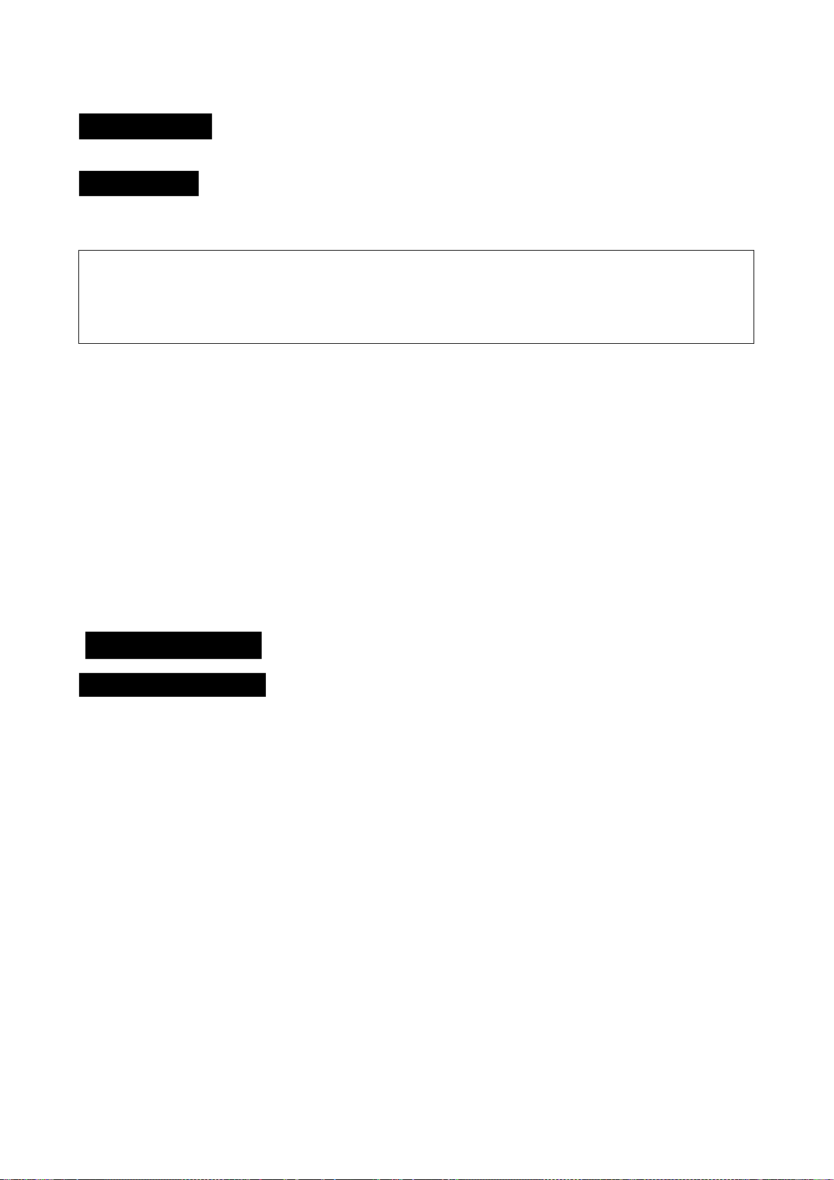
Main menu page:
9
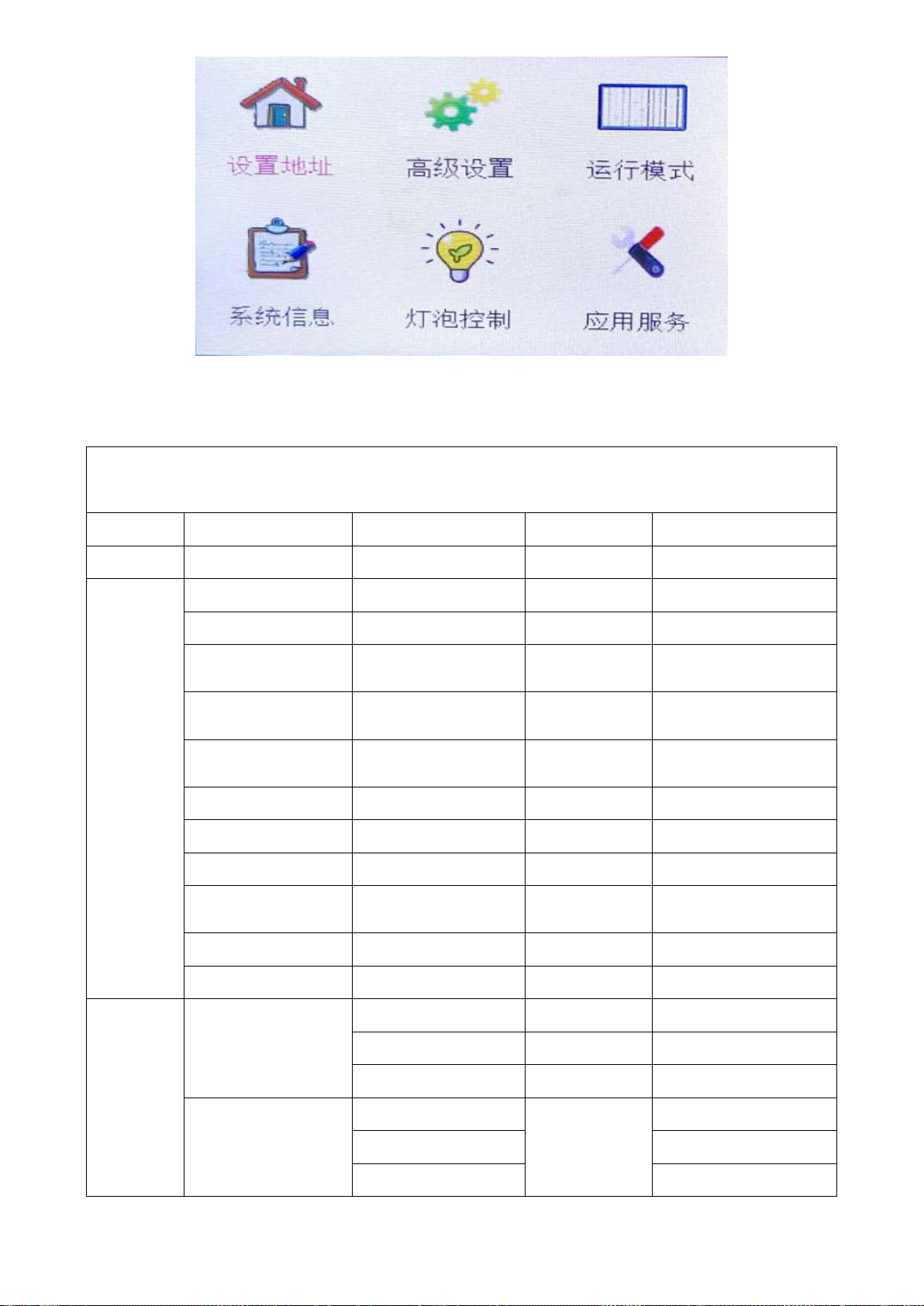
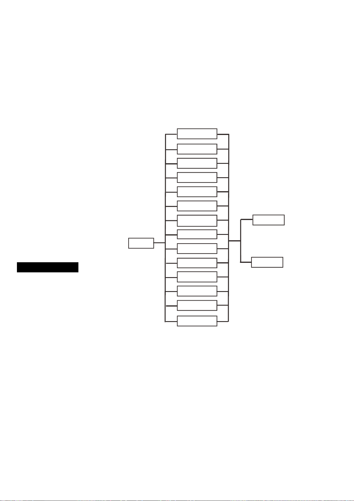
The main function show as below:
Menu function
Level 1 menu
Level 2 menu
Level 3 menu
Level 4 menu
Level 5 menu
Set address
0-512
Advanced
settings
Horizontal reversal
Yes/No
Vertical reversal
Yes/No
Display screen
reverse
Yes/No
Display screen
automatically reverse
Yes/No
The display is always
bright
Yes/No
(Default delay off)
Horizontal angle
180°/360°/540°
(Factory default 540°)
Vertical angle
90°/180°270°
(Factory default 270°)
Wireless link
Yes/No
Voice
Chinese/English
(Factory default
Chinese)
Error message
Yes/No
Factory settings
Operating
mode
Select channel mode
Full mode 24(CH)
Yes/No
(Factory default)
Full mode 18(CH)
Yes/No
Lite mode 15(CH)
Yes/No
View the current
channe
horizontal
0-255
.......
Functional channel

10
Manual control of
Fixture
automatic testing
Manual test
Horizontal
0-255
Vertical
0-255
......
0-255
Strobe
0-255
Fixture reset
Horizontal and
Vertical
Yes/No
Color
Yes/No
Gobo
Yes/No
Strobe
Yes/No
Focusing and
prism
Yes/No
All
Yes/No
Built-in program
Built-in
program1
Yes/No
......
Yes/No
Built-in
program9
Yes/No
System
message
Device version
number
Equipment
temperature
Fan speed
Error detection
Equipment running
time
Lamp time
Lamp
control
Bright light bulb
Yes/No
Turn on the electric
light bulb
Yes/No
Console control light
bulb
Yes/No
Turn on lamp delay
0-535
Half power delay
0-535
Reset lamp time
Yes/No
Lamp maintenance
internal use
0-255
Remaining
maintenance time
Repeat/no
Application
Service Contact

11
service
Equipment
maintenance times
Equipment fine-
tuning calibration
Device data clear
Equipment usage
records
12
Device fine-tuning settings
Select the device fine-tuning setting, press the ENTER button to confirm, the device fine-tuning setting (password:
1212), enter the initial setting menu to adjust the initial position of each motor. Press the ENTER button to confirm. Use
the UP/DOWN button to select the submenu, press the ENTER button to save and automatically return to the previous
menu. Press the MENU button to exit.
5.2 Error message
Temperature error
The temperature detection board may
be damaged.
Fan error
The fan and its control parts may be broken.
Magnetosensitive error
For the magnetic sensitive function part may be broken.
Optocoupler error
Optocoupler and its control part may be broken.
The above situation may occur when the Fixture is turned on or reset, some parts may be damaged.
Please contact an authorized service center.
Fine-tuning
255
0
Physical address3
Physical address4
Physical address3
Strobe
Focus
Prism2
rotation
Prism2
Prism 1 rotatio
n
Prism1
Gobo
Color1
Color
Vertical
Horizontal

13
6. Universal DMX controller control
6.1 6.1 Connection
1. In order to reduce signal errors and avoid signal attenuation and interference during
transmission, a 90-120Ω (0.25W) resistor can be added between the 2-core and 3-core of the
DMX output of the last machine.
2. Connect the fixture with XLR signal cable, one end is connected to the output port of the fixture, and the
other end is connected to the input port of the next fixture. XLR signal lines can only be used in series, not
in parallel. DMX512 signal transmission speed is very fast. Damaged signal wires, weak soldering, poor
contact, etc., will affect signal transmission and cause the system to shut down
3. When the machine power supply of a unit is disconnected, the connection of DMX output
and input is bypassed in order to maintain the connection of the DMX line.
4. Each lamp must have an address code, which can receive the information sent by the console, and the
range is 0-511 (usually 0&1 and 1 are the same).。
5. The terminal of the DMX512 system needs to be equipped with a terminal to reduce errors in signal
transmission.
6. 3-pin XLR connector:
3 core XLR: PIN 1: GND, PIN 2: negative signal, PIN 3: positive signal.
14
6.2 6.2 Channel settings
Press the ENTER button to enter the menu mode, select the operating mode → select channel mode, press
the ENTER button to confirm, the current channel mode will flash on the display, use the UP and DOWN
buttons to select the full mode 24 (CH), press the ENTER button to save. Press the MENU button to return
to the previous menu or wait 30 seconds and automatically exit the menu mode.
6.3 6.3 Address code setting
When using a general DMX controller to control fixture, you need to set the starting address (1-512) for the
fixture so that the machine can receive DMX signals.
Press the ENTER button to enter the menu mode, select the DMX function, press the ENTER button to
confirm, the current address will flash on the display, then use the UP/DOWN button to select the address
code (1-512), press the ENTER button to save. Press the MENU button to return to the previous menu or
wait 30 seconds and automatically exit the menu mode.
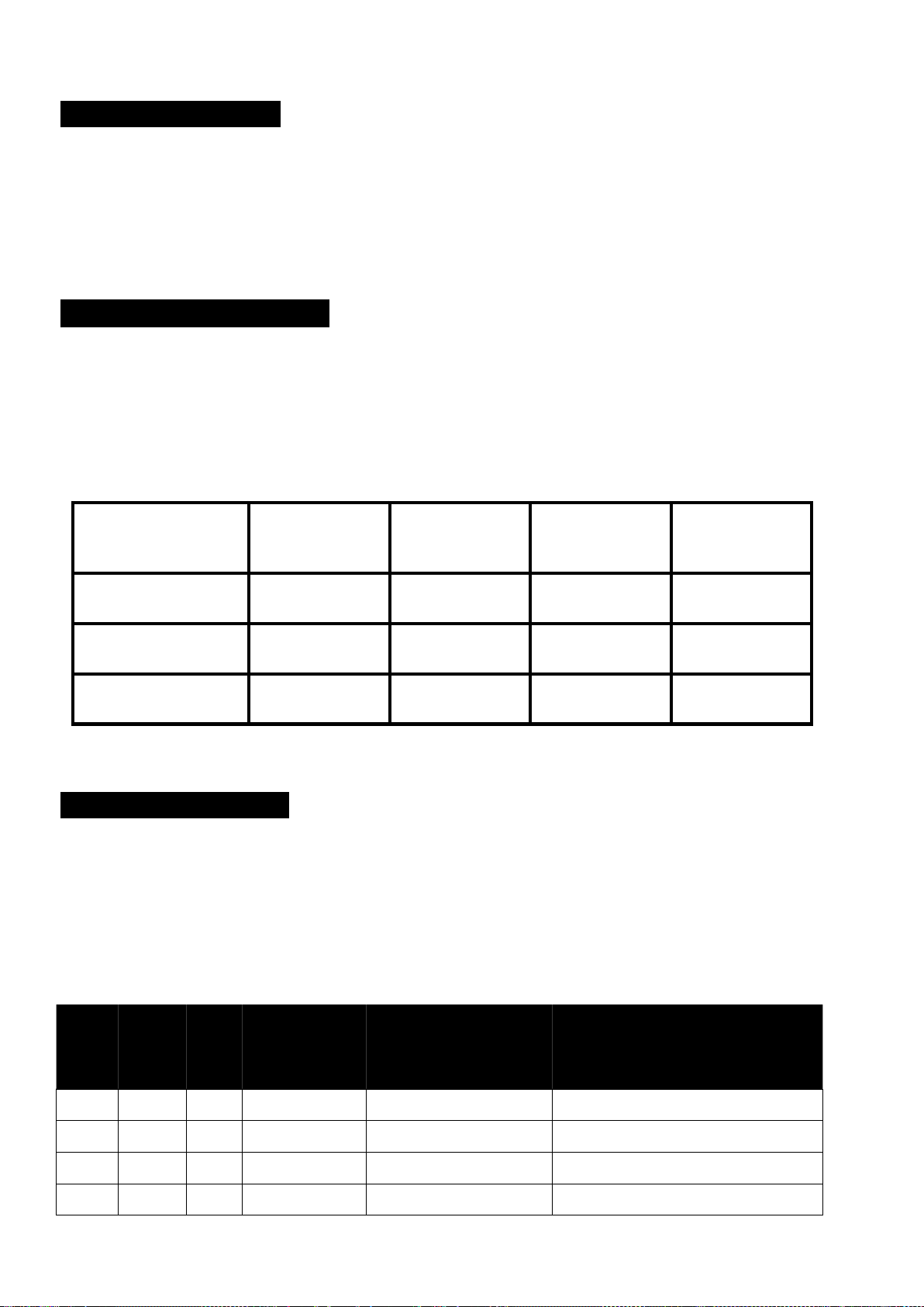
Please refer to the following chart to set the address codes of the first 4 fixtures
Channel mode
Fixture 1 address
code
Fixture 2 address
code
Fixture 3 address
code
Fixture 4 address
code
Full mode (24 channels)
1
25
49
73
Standard mode (18
channels)
1
19
37
55
Lite mode (15 channels)
1
16
31
46
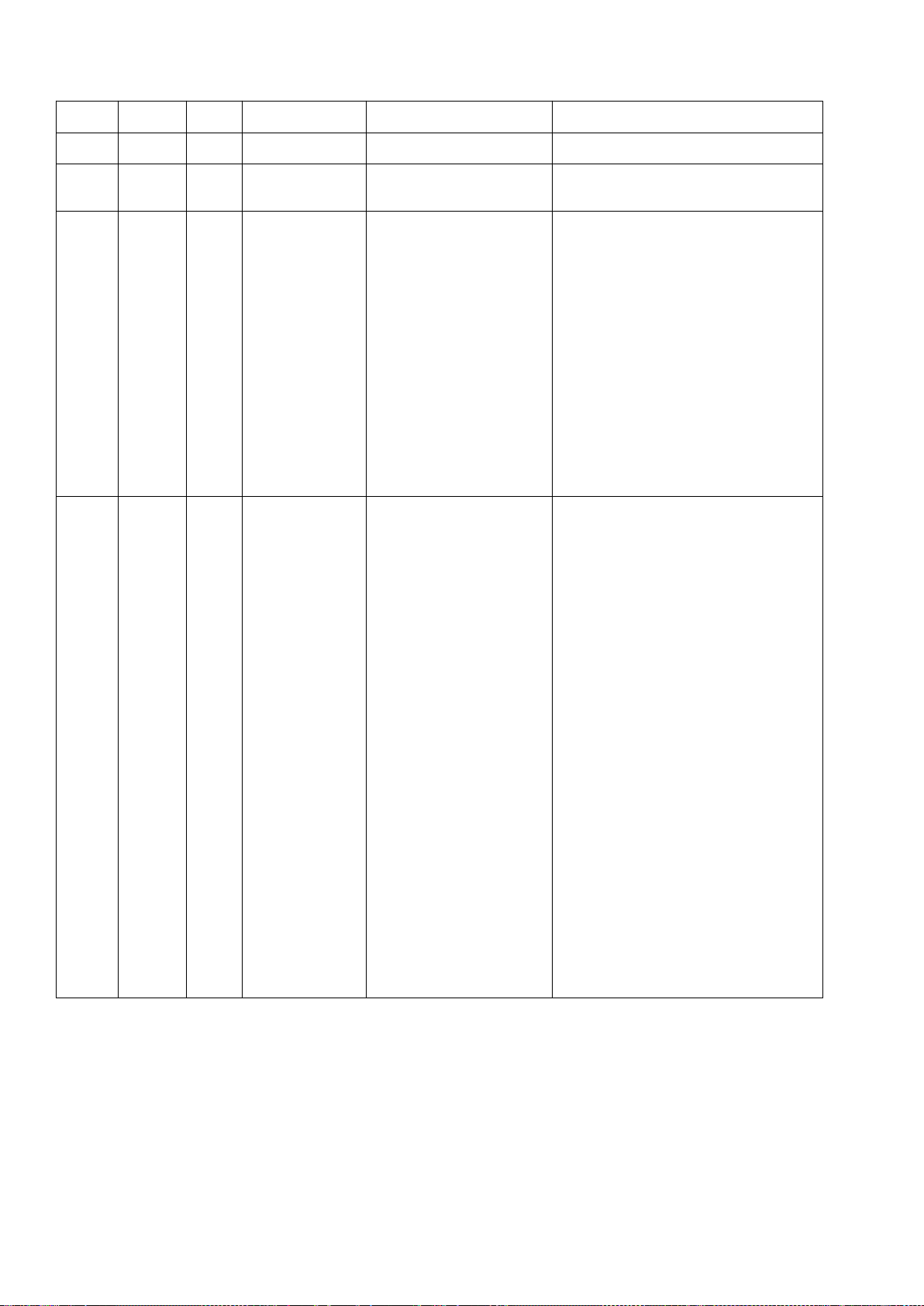
6.4 6.4 DMX 512 channel
Please refer to the following channel diagram to control
Notice:
1. If the DMX signal is cut off, the fixture will remain in the state before the signal was cut off, unless reset.
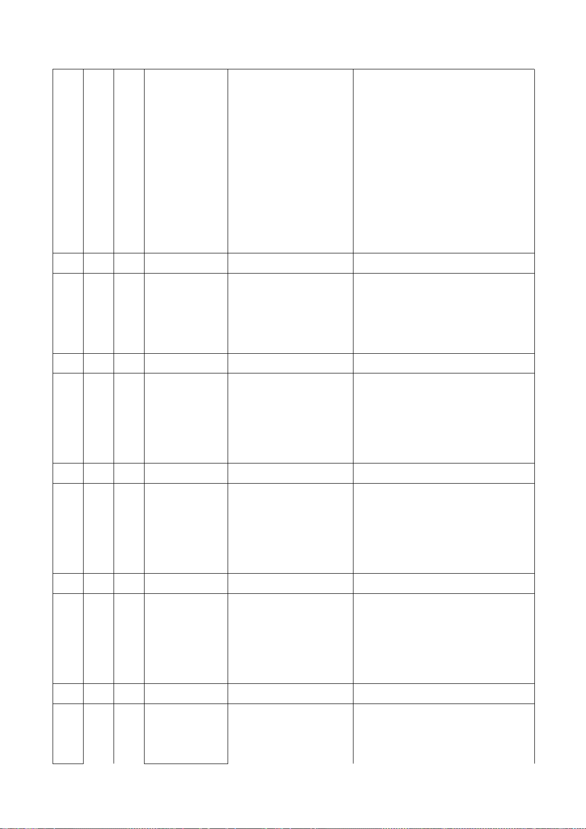
Channel chart:
Full
mode 24
(CH)
Standard
mode 18
(CH)
Lite
mode
(15
(CH)
Channel
name
Channel value
Features
1
1
1
Horizontal
000-255
0-540 degree
2
2
Horizontal
000-255
16bit Adjustable
3
3
2
Vertical
000-255
0-270
degree
4
4
Vertical
000-255
16bit Adjustable
15
5
5
3
XY speed
000-255
From fast to slow
6
6
4
Dimming
000-255
Light spot from dark to light
7
7
Dimming fine-
tuning
000-255
16bit adjustable
8
8
5
Strobe
0-7
No function
8-15
Open
16-131
Synchronous strobe, from slow to
fast
132-167
Fast closing and slow opening,
from slow to fast
168-203
Slow to close and fast to open,
from slow to fast
204-239
Pulse strobe, from slow to fast
240-247
Random strobe, from slow to fast
248-255
Open
9
9
Color wheel 1
0-4
White light
5-9
Deep red
10-14
Blue
15-19
Green
20-24
Orange
25-29
Magenta
30-34
Yellow
35-39
Cyan
40-44
Red
45-49
Navy blue
50-54
Dark green
55-59
Yellow-green
60-61
White light
62-159
Color position/half color
160-219
Positive rainbow, from fast to slow
220-223
Stop
224-255
Reverse rainbow, from slow to fast

16
10
10
7
Color wheel 2
0-4
White light
5-9
Plum red
10-14
Light blue
15-19
Light green
20-24
Orangered
25-29
Brownish yellow
30-34
light yellow
35-39
Iridescent
40-44
Light blue purple
45-49
CTB
50-54
CTO 3200K
55-59
CTO 5600K
60-61
White light
62-159
Color position/half color
160-219
Positive rainbow, from fast to slow
220-223
Stop
224-255
Reverse rainbow, from slow to fast
11
11
8
Gobo
0-3
White light
4-7
Gobo1
8-11
Gobo2
12-15
Gobo3
16-19
Gobo4
20-23
Gobo5
24-27
Gobo6
28-31
Gobo7
32-35
Gobo8
36-39
Gobo9
40-43
Gobo10
44-47
Gobo11
48-51
Gobo12
52-55
Gobo13
56-59
Gobo14
60-63
Gobo14 dithering effect, from slow
to fast
64-67
Gobo13dithering effect, from slow
to fast
68-71
Gobo12dithering effect, from slow
to fast
72-75
Gobo11dithering effect, from slow
to fast
76-79
Gobo10dithering effect, from slow
to fast
80-83
Gobo9dithering effect, from slow
to fast
84-87
Gobo8dithering effect, from slow

17
to fast
88-91
Gobo7dithering effect, from slow
to fast
92-95
Gobo6dithering effect, from slow
to fast
96-99
Gobo5dithering effect, from slow
to fast
100-103
Gobo4dithering effect, from slow
to fast
18
104-107
Gobo3dithering effect, from slow to
fast
108-111
Gobo2dithering effect, from slow to
fast
112-115
Gobo1dithering effect, from slow to
fast
116-119
White light
120-189
Dynamic wheel rotates forward,
from slow to fast
190-193
Stop
194-255
Dynamic wheel reverse rotation,
from slow to fast
12
Prism 1
0-255
Sixteen prism
13
Prism 1 rotation
0-127
Sixteen prism rotation position
128-189
Forward rotation, from fast to slow
190-193
Stop
194-255
Reverse rotation, from slow to fast
14
Prism 2
0-255
Three rows of 48 honeycomb prisms
15
Prism 2 rotation
0-127
Three rows of 48 honeycomb prism
rotation positions
128-189
Forward rotation, from fast to slow
190-193
Stop
194-255
Reverse rotation, from slow to fast
16
Prism3
0-255
24 honeycomb prism
17
Prism3 rotation
0-127
24 honeycomb prism rotation
position
128-189
Forward rotation, from fast to slow
Stop
Stop
194-255
Reverse rotation, from slow to fast
18
Prism4
0-255
4 rows of mirrors (symmetrical)
19
Prism4 rotation
0-127
4-row mirror (symmetrical) rotation
position
128-189
Forward rotation, from fast to slow
190-193
Stop
194-255
Reverse rotation, from slow to fast
20
Prism5
0-255
8 prism
21
Prism5 rotation
0-127
8 prism rotation position
128-189
Forward rotation, from fast to slow
190-193
Stop

19
194-255
Forward rotation, from fast to slow
12
9
12 Prism wheel
1
0-15
No function
16-95
Prism Wheel 1 Effect 1
96-175
Prism Wheel 1 Effect 2
176-255
Prism Wheel 1 Effect 3
13
10
Prism wheel 1
rotation
0-127
Prism rotation position
128-189
Forward rotation, from fast to slow
190-193
Stop
194-255
Reverse rotation, from slow to fast
14
11
Prism wheel 2
0-15
No function
16-127
Prism Wheel 2 Effect 1
128-255
Prism Wheel 2 Effect 2
15
12
Prism wheel 2
rotation
0-127
Prism rotation position
128-189
Forward rotation, from fast to slow
190-193
Stop
194-255
Reverse rotation, from slow to fast
22
16
13
Focusing
0-255
Focusing focal length
23
17
14
Fog
0-15
No function
16-255
Fog
24
18
15
Functional
channel
0-129
No function
130-139
Turn on the bulb
140-149
XY Reset
150-159
Color reset
160-169
Gobo reset
170-179
Strobe reset
180-189
No function
190-199
Focus/prism reset
200-209
Reset all
210-229
No function
230-239
Turn off the bulb
240-255
No function

20
7. Fault Handling
The following are some of the problems that often occur during operation, with some
suggestions for Fault Handling:
A. The lamp does not work, there is no light, the fan does not running
1. Check the power contact and whether the fuse is intact.
2. Check the voltage.
3. Check the indicator light of the power switch.
B. Out of the control of the controller
1. Check the DMX signal connector and signal cable to see if they are properly connected.
2. Check whether the address code setting is correct.
3. If the DMX signal transmission is intermittent, check whether the connection between the XLR
seat and the signal cable is good.
4. Try it with another controller.
5. Check if the distance between the DMX signal wire and the high-voltage wire is too close,
which will damage or interfere with the signal circuit.
C. Channel fails
1. 1. Stepper motor or motor lead may be damaged.
2. 2. The drive circuit of the motor may be damaged.
D. Good and bad bulbs
1. 1. The bulb cannot be lit normally. See if the voltage is too high or too low.
2. 2. The internal temperature may be too high. If necessary, replace the cooling fan.
Table of contents
Popular Light Fixture manuals by other brands

Chauvet
Chauvet S-Mover user manual

Triarch
Triarch 29764 instructions

Foxfury Lighting Solutions
Foxfury Lighting Solutions NOMAD 360 product manual

Richelieu
Richelieu LEDDY 7 quick start guide

Energetic Lighting
Energetic Lighting MXL2048-LED40K8040 installation instructions

Party Light & Sound
Party Light & Sound PARTY-WASH7 user manual


Avlite
Avlite AV-OL-ILAB-UM-R-D Installation & service manual

F&V
F&V R300 Lumic quick start guide

Hayward
Hayward LPCUS11 Series Installation and operation manual

Raytec
Raytec VARIO2 i16 Quick start up guide

Designplan
Designplan ICE LED 1.0 installation instructions

IKEA
IKEA BASISK PENDENT LAMP 8" instructions