VM VM-HF610 User manual
Honda CB650F / CBR650F (2018+) Fender Eliminator Installation Instructions
TOOLS REQUIRED:
o5mm allen wrench
oRatchet (1/4” or 3/8” drive) and extension
o8mm, 10mm sockets
o8mm hex wrench
oPhillips screwdriver
oFlat head screwdriver
oFlush cutting pliers
INSTALLATION VIDEO:
We’ve created a YouTube video to help explain the installation steps in more detail. Search “Vagabond Motorsports 2018 Honda
CB650F Fender Eliminator Install” or use the link: https://youtu.be/qHAMdcw6Qxo
INSTALLATION STEPS:
1. Remove the rider’s seat (key in left side of frame).
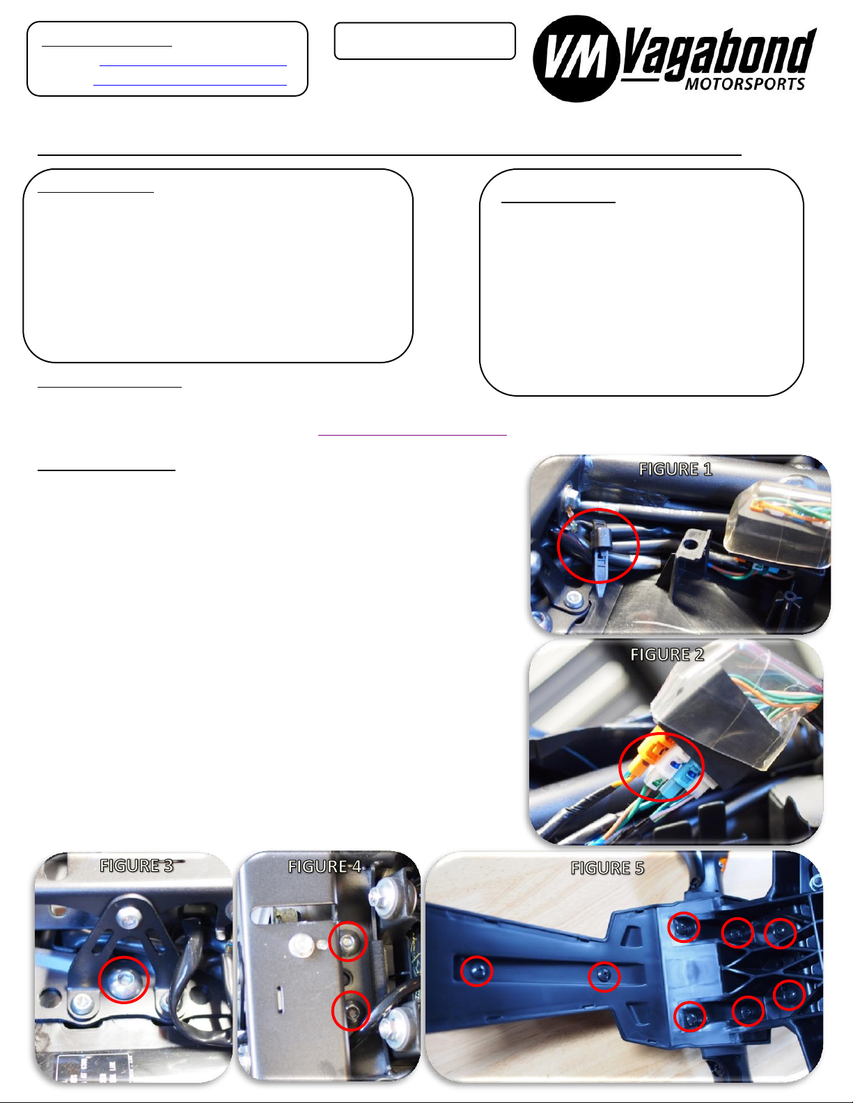
2. Remove the reusable cable tie securing the wiring looms together (FIGURE 1).
3. Pull the electrical connector block up off its plastic tab and separate the black
rubber boot (FIGURE 2). Disconnect the orange, white, and blue 2-pin
connectors for the turn signals and license plate light. A small flathead
screwdriver is useful to gently lift the locking tab on the connectors.
4. Remove the factory rear fender assembly from the motorcycle (3X 5mm allen
head bolts, FIGURE 3 and FIGURE 4). One of these bolts will be reused so set
aside. The single forward bolt should be accessible with a standard L-key allen
wrench without removing the triangular brace around it. Gently guide the
three wiring looms out of two holes in the undertail tray, noting that blue
connector needs to be guided under the subframe cross bar and out the hole
on the right (brake) side of the undertail.
5. Remove the license plate from the OEM rear fender. (2X Phillips head screws
and 10mm nuts, hardware may vary dealer to dealer). This hardware will be
reused to mount the license plate to the fender eliminator so do not discard.
6. Remove the plastic cover from the factory rear fender assembly (8X Phillips
head screws, FIGURE 5). Starting at the rear portion, pop the cover panel off of
its retaining tabs, using a flathead screwdriver to help pry it as needed.
Questions/Comments:
Visit us at www.vagabondmotorsports.com
Or email sales@vagabondmotorsports.com
P/N: VM-HF610
Fender
Eliminator
1X M4 bolts
(for OEM
KTM
license
plate light)
2X cable-tie
mounts
2X cable-tie
mounts
2X rubber
bumpers
(prevents
license
plate
vibration)
Fender
Eliminator
1X M4 bolts
(for OEM
KTM
license
plate light)
2X cable-tie
mounts
2X cable-tie
mounts
2X rubber
bumpers
(prevents
license
plate
PARTS INCLUDED:
Fender Eliminator Body
2X Turn signal spacers
2X M6 flanged nuts
2X Aluminum spacers
2X Rubber bumpers
2X Rubber grommets
1X Cable tie
1X Cable tie mount
1X M4 bolts (for OEM KTM license
plate light)
2X cable-tie mounts
2X cable-tie mounts
2X rubber bumpers (prevents license
plate vibration)
Fender Eliminator
1X M4 bolts (for OEM KTM license
plate light)
2X cable-tie mounts
2X cable-tie mounts
2X rubber bumpers (prevents license
plate vibration)
Fender Eliminator
1X M4 bolts (for OEM KTM license
plate light)
2X cable-tie mounts
2X cable-tie mounts
2X rubber bumpers (prevents license
plate vibration)

7. Remove the license plate light assembly from the OEM rear fender (2X Phillips head screws, FIGURE 6). Pull light assembly and wire
harness through the hole in the fender and set aside.
8. Remove the license plate light from the OEM plastic spacer (2X 8 mm nuts, FIGURE 7). Remove and keep the nuts, rubber gasket
and steel bushing spacers from the license plate light as they will all be reused.
9. Remove the right and left turn signals from the OEM fender (Phillips head screw, FIGURE 8). Remove turn signal body, steel
mounting bracket, screw, and the rubber base grommet as they will all be reused.
10. Begin assembly of the fender eliminator by installing the license plate light OEM
rubber gasket and bushings (FUGURE 9A), turn signal base grommets (FIGURE 9B),
and the supplied cable tie mount in the hole in the fender eliminator (FIGURE 9C).
11. Install right (blue connector) and left (orange connector) turn signals into fender
eliminator using the supplied silver metal spacers in between the steel mounting
bracket and the base grommet (FIGURE 10 arrow). Make sure the spacer is sitting
flush with the grommet perimeter before tightening the turn signal mount screws.
12. Install the license plate light with the factory lock nuts (8mm socket and wrench
required, FIGURE 10A). Tighten until the nuts bottom out on the mount bushings
and the light is firmly seated on it gasket.
13. Use the supplied cable tie to secure the three wiring looms to the cable tie mount
(FIGURE 10B). Route the wiring looms in an “X” shaped through the cable tie and
then through the two oval slots in the fender eliminator. The blue connector will
go through the hole nearest the right turn signal, and the other two wiring looms
will go through the other slot (FIGURE 11). Trim the cable tie flush after tightening.
14. Thread the electrical connectors through the two supplied grommets and pull the
grommets over the wiring looms toward the fender eliminator. Install the
grommets into the fender eliminator body by pushing the groove of the grommet
into the slots on the fender eliminator (FIGURE 11).
15. Install the assembled fender eliminator on the motorcycle. Use the supplied
aluminum spacers on the two threaded studs between the fender eliminator and
undertail. Start by threading all the electrical connectors through the two holes in
the plastic undertail and then line up the two threaded studs on the fender
eliminator with the holes on the motorcycle subframe. Secure the fender
eliminator to the motorcycle with the supplied flanged nuts. Use one of the factory
fender bolts from Step 4 in the front threaded insert of the fender eliminator.
16. Route the wiring looms in the factory manner, and use the reusable cable to
secure a service loop of the excess wiring. Reconnect the three connectors.
17. Re-install rear seat and install the license plate with the original dealer-supplied
hardware. Perform a system test to ensure all lights are functional and double
check that all hardware is tight before riding the motorcycle.
TERMS & CONDITIONS
Legal Notice: The purchaser and/or user of any Vagabond Motorsports, LLC branded parts releases Vagabond Motorsports, LLC from all liabilities pertaining to use of the parts. The user
acknowledges that any modification, alteration or change to a motorized vehicle may increase the risk of accident and/or injury. Additionally, the user acknowledges any change may render
the motorized vehicle illegal for use in public roads. Warranties: All Vagabond Motorsports, LLC branded products carry a one-year limited liability against workmanship and material defects.
This Warranty is provided to the original purchaser of the products. Return Policy: All approved returns must be in new and unused condition within 90 days of purchase.
Popular Motorcycle Accessories manuals by other brands

Ohlins
Ohlins SU 932 Mounting instructions

HealTech Electronics
HealTech Electronics GIpro DS Series Installation and operation manual

KTM
KTM 64108915044 Information

hepco & becker
hepco & becker 6307551 00 01 manual

BoxerCafe
BoxerCafe Battery Relocation Kit instruction sheet

BEROTEC
BEROTEC CUMPAN FANTIC Caballero 125 user guide


