manuals.online logo
Brands
  1. Home
  2. •
  3. Brands
  4. •
  5. Takegawa
  6. •
  7. Motorcycle Accessories
  8. •
  9. Takegawa Hyper S-stage User manual

Takegawa Hyper S-stage User manual

COPY
‑1‑ Nov./14/11
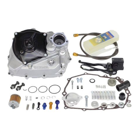
Hyper S-Stage V KIT
Instruction Manual
Thank you for purchasing one of our products. Please strictly follow the following instructions in installing and using the product. Before fitting the products,
please be sure to check the contents of the kit. Should you have any questions about the product, please kindly contact your dealer.
Cautions about fuel to use
This product is so designed to achieve a higher compression ratio than stock engines. As for the fuel, high-octane gasoline
should always be used. In case regular gasoline is used, abnormal combusiton takes place, and the engine cannot achieve its
original performance. Moreover, it is highly likely that the piston will break down, leading to serious breakdown. Before installing,
make sure that no regular gasoline remains in the fuel tank. In case regular gasoline is remaining in the fuel tank, do replace it
with high-octane gasoline.
Cautions about spark plug
Please be sure to replace the spark plug with CR8HSA (NGK) or U24 FSR-U (DENSO). In the case of a non-resistive plug,
please replace with C8HSA (NGK) or U24 FS-U (DENSO).Subsequently, choose and use a right spark plug with the right level,
depending on the degree of burning of the spark plug electrode section.
Cautions about sprocket
The installation of this product will increase the power of your vehicle. So use of a stock sprocket will result in hard wears of
parts, not only adversely affecting the engine life, but also breaking the engine in the worst case. Please replace the sprocket
with the high-geared one. Read the instructions carefully before installation
・Work only when the engine and the muffler are cool. (Otherwise, you will burn yourself.)
・Prepare right tools for the work, and do the work in the proper and right way.(Otherwise, improper work could cause breakage of parts or injuries to  
 yourself.)
・Always use a torque wrench to screw bolts and nuts tight and securely to the specified torque. (Otherwise, improper torque may result in the breakage
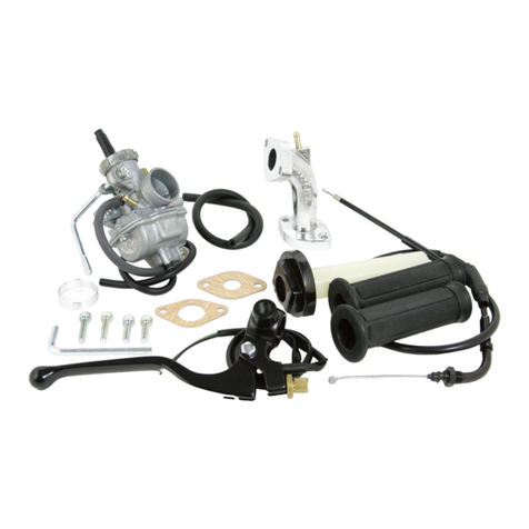
 or coming off of bolts and nuts.)
・As some products and frames have sharp-pointed or protruding portions, please work with your hands protected. (Otherwise, you will suffer injuries.)
・Before riding, always check every section for slack in parts like screws. If you find slack ones, screw them securely up to the specified torque.
 (Or improper torque may cause parts to come off.)
 ※ Be sure to retighten the cylinder head to the specified torque.
・Please replace gaskets and packings with new ones withoutfail. Check carefully those parts to be reused, and in case wear or damage is detected,  
 always replace them with new ones.
The following show the envisioned possibility of injuries and damages to human bodies as a result of conduct disregarding the following cautions
CAUTION
The following show the envisioned possibility of human death or serious injuries as a result of conduct disregarding the following cautions
・Always drive the engine in a well-ventilated place, and do not switch the engine on in an airtight place. (Otherwise, you will suffer from carbon monoxide
 poisoning. )
・When you notice something abnormal with your motorcycle while riding down a road, stop riding immediately and park your motorcyle in a safe place.
 (Otherwise, the abnormaility could lead to an accident.)
・Before doing work, place the motorcycle on level ground to stablize the position of your motorcycle for safety’s sake. (Otherwise, your motorcycle could
 fall down and injure you while you are working.)
・Check or perform maintenance of parts correctly according to the procedures in the instruction manual or a service manual. (Improper checking or  
 maintence could lead to an accident.)
・If you find damaged parts when checking and performing maintenance, do not use these parts any longer, and replace them with new ones.
 The continued use of these damaged parts as they are could lead to an accident.)
・Since gasoline is very ignitable, keep everything that may fire away. Also, since vaporized accumulation of gasoline has a explosion hazard, keep
 well-ventilated place to work on.
WARNING
◎We do not take any responsibility for any accident or damage whatsoever arising from the use of the products not in conformity with the instructions in
 the manual.
◎Installation of this product requires processing of the stopper part of the throttle pipe. Moreover, please note that the processing disables the use of an
 acceleration limiter.
◎We shall be held free from any kind of warranty whatsoever of products other than this product if the glitch takes place on the other products than
 this one after the installation and use of this product.
◎If you make alterations to the product outside our factory, we shall be held free from any guarantee of the product.
◎You are kindly requested not to contact us about the combination of our products with other manufactureres'.
◎This product is designed for exclusive use in the above-mentioned types of motorcycles and frame numbers only. Please take note that this product  
 cannot be mounted on other types of motorcycles.
◎Please install this product correctly, referring to the HONDA genuine service manual for the above-mentioned model numbers of the motorcycles.
◎Before installation, prepare tools and the like listed in page 2, and install the parts with utmost care, referring to the “Installation Procedures.” In addition,
 this instruction munual as well as HONDA’s service manual is prepared with those in mind who have basic technical skills and knowledge. So,it is   
 advisable that those who do not have such tools, or skills or knowledge contact a technically reliable specialist shop for installation.
◎The supplied cylinder and cylinder head gasket differ from genuine ones in thickness. Please take note, these parts cannot be used in combination with
 other manufacturers’ parts as well as genuine parts. And please use our parts for repairs.
◎A stock carburetor will interfere with the supplied cylinder. So, please process the interefering part in case you install a stock carburetor.
◎Bolts, nuts, and dowel pins will be reused. However, be sure to replace worn-down or sevrely-damaged ones with new ones.
◎You cannot run the motorcycle in the rain with kit’s filter installed. Otherwise, it could cause the engine trouble.
◎Please note that, in some cases, the illustrations and photos may vary from the actual hardware.
ItemNo.
01―05―3106 (Paper-type filter)
01―05―3108 (Sponge-type filter)
Applicable to
CRF50F
XR50R
 Frame No.
:AE03-1400001〜
:AE03-1000001〜
COPY
‑2‑ Nov./14/11
Lesson
◇Usually, bolts and nuts are loosened by counterclockwise turn, and tightened by clockwise turn.
◇When tightening a screw, at first tighten it by hand as tight as you can. If you cannot get it moving more than one or two turns, check if the screw is
 placed at an angle.
◇To loosen a screw means turning a tightened screw around three or four times counterclockwise, and to unscrew it means turning it around    
 counterclockwise until it comes off.
◇To tighten a screw means to keep a screw from getting loose. The numeric value as a guide at which a screw will not break or get loose when  
 tightened is the so-called "tightening torque." If you do not have a torque wrench, please try to tighten a screw as tight as possible to the level where
 the screw will not break or get loose, though we can not take any responsibility for the breakage. In case we do not use a torque wrench, we need
 to judge, only by intuition or using experience, the degree of tightening power at which the bolt will break or get loose.
◇Improper use of tools will result in breakage of the top of a bolt or screw.
◇Contents of Kit
1
2
3
4
5
67
8
9
10
11
12 13
14
15 16
17
18
19
20 21
22
23
24
25
26
27 28 29 30
01―02―517
Piston kit
◎Please be informed that, mainly because of improvement in performance, design changes, and cost increase, the product specifications and prices
 are subject to change without prior notice.
◎This manual should be retained for future reference.
No. Parts' Name Qty Repair Part Item No. in packs of No. Parts' Name Qty Repair Part Item No. in packs of
1Piston 113101-NSH-T00 103-01-110 (Paper-type filter) 1
2Piston ring set 101-15-014 103-01-1105 (Sponge-type filter) 1
3Piston pin, 13 x 36 113111-GEF-T01 1 18 Carburetor gasket 116201-GEY-T01 1
4Piston pin circlip 200-01-0003 6 19 Inlet pipe gasket 191301-181-T01 1
5Cylinder 101-01-0222 1 20 6x20 socket cap screw 200-00-0043 10
6Cylinder gasket 100-01-0067 2 21 6x25 socket cap screw 200-00-0089 10
7Cylinder head gasket 112251-GFL-T10 1 22 710 mm throttle cable 109-02-0071 1
8Cylinder head cover gasket 100-01-0156 2 23 Spark plug CR8HSA 1
9R side cover gasket 100-01-0157 2 24 Main jet #85 100-03-0041 1
10 L side cover gasket 100-01-0158 2 25 Drive sprocket, 15T 102-05-022 1
11 Tappet cap O-ring 200-01-0034 4 26 Tank spacer 216954-GEL-T00 1
12 Exhaust pipe gasket 100-01-0064 2 27 Flange bolt, 8x25 100-00-0318 5
13 Rubber packing (black) 100-01-0066 2 28 Flange bolt, 8x30 100-00-0181 4
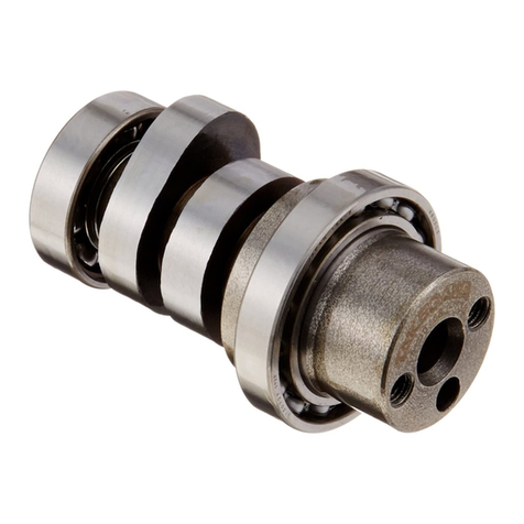
14 Camshaft 101-08-0009 1 29 Spacer, 8.2x10x9.5 100-00-0199 4
15 PC18 carburetor assembly 103-03-031 1 30 Washer 100-00-0201 6
16 Intake manihold 117111-GBO-T00 1
17 Air filter (with a band) 1
※Please order repair parts with the Repair Part Item No. Without the repair part item No., we may not be able to provide the correct parts.
Some parts are only available as a set. Please order them with the set number.
COPY
‑3‑ Nov./14/11
Names of components
Right-side cylinder head side cover
Right-side cylinder head
side cover gasket
Cylinder head cover
Valve rocker arm
Tappet adjusting screw
Tappet adjusting nut
Valve rocker arm shaft
Sealing washer, 6 MM
Flange bolt, 6x20
Flange bolt, 6x110
(Copper or a aluminum)
sealing washer, 6.5 x12
O-ring, 30 MM
Tappet adjusting hole cap
Exhaust pipe gasket
Cylinder head cover gasket
Hex nut, 6 MM
Sealing washer A, 6 MM
(Copper plated)
Cap nut, 6 MM
Cam shaft COMP.
Cam sprocket
Left-side cylinder head side cover
Left-side cylinder head
side cover gasket
Dowel bolt, 5 MM
※1 Dowel pin, 8x12
※3 Spark plug
Tappet adjusting hole cap
O-ring, 30 MM
Inlet pipe gasket
※1Dowel pin, 8x14
Cylinder head gasket
※2
Cylinder
Piston ring set
Piston pin circlip
Piston pin
Piston
Rubber packing, 16 MM
Cylinder gasket
※1 Dowel pin, 8x12
Guide roller bolt
Washer, 8 MM
Bolt, 6 MM
Cam chain guide roller COMP.
※1 Dowel pin, 8x14
Bolt, 6 MM
※1 The length of the dowel pins differs depending
   on the use, which please note.
※2 These hardware is not included in the kit or
   will not be used for the installation of this kit.  
※3 Be sure to change to CR8HSA (NGK) or
   U23FSR-C (DENSO).
COPY
‑4‑ Nov./14/11
◇Shift the tube clip to disconnect the fuel tube.
◇Detachafuelhosefromthecarburetor,andthentwo
 boltsonthefueltanktoremove thetank.
Stock Parts Removal
1.Exterior Parts Removal
A seat / shroud /
rearfenderassembly Trim clip
Screw
Bolts
◇Removeeachtwooftrimclips,screws,andbolts 
 first,andthenremoveaseat/shroud/rearfender 
 assembly. Inner pin
 Toolstouse:
 10mm offset box wrench
 Slotted screwdriver (Midsize)
◇Atrimgrip canberemovedbyliftinganinner pinwith
 aslottedscrewdriverorothertools.
◇Turn off the fuel cock.
2.Carburetor Removal
◇Removecarburetor’stopcap,andthentakethethrottle
 valveoutfromthecarburetor.
◇Removeastoragetankhose.
◇Removethe bolts on the aircleaner stay.
 Toolstouse:
 10mm socket
 Extension bar (Small)
◇Removetwoboltswhicharefixingthe inlet pipe to the
 cylinderhead.Then,removetheinlet pipe, the
 carburetor,and the air cleaner.
 Tooltouse:
 8mm offset box wrench
◇Install the earth wire on the frame with the bolts of air
 cleanerstay.
 Toolstouse:
 10mm socket
 Extension bar (Small)
 Torque:12 N・m(1.2 kgf・m)
3.Muffler Removal
 Tooltouse:
 10mm open-endwrench
◇Removetwo nuts in the exhaust pipe.
 Tooltouse:
 12mm offset box wrench
◇Removemufflerstay’sboltsandthen,the muffler.
4.Front Fender Removal
5.Spark Plug Removal
 Toolstouse:
 10mm socket
 Extension bar (Small)
◇Removethree bolts on the reverse side first, and
 removethefrontfender.
◇Pullouttheplugcapfromtheplugtoremoveit.Besure
 to hold the cap in pulling it out.
◇Removetheplugwiththein-vehiclesparkplugwrench.
6.Cylinder Head Left Cover
 Removal
◇Byremoving the hexboltinthecenter of theright-side
 coverofthecylinderhead,youcanremovetheleftcover.
 (Ifyoucannotremovetheleftcoverinthisway,screwin
 thehexboltbytwotothreescrewthreads, striketopof
 thebolts lightly, andthenyoucanremovethecover.)
 Tooltouse:
 10mm socket
7.Crankcase Left Cover
 Removal
◇Removeshiftpedal’shexboltandthen,theshiftpedal.
 Tooltouse:
 10mm offset box wrench
◇Removethree bolts which arefixing the crankcase
 leftcover.
 Tooltouse:
 8mm deep socket
8.Two Tappet Caps Removal
 Tooltouse:
 17mm offset box wrench
◇Removetwotappetcaps.
Bolt
Collar
Fuel tank
Washer
COPY
‑5‑ Nov./14/11
9.Cam Sprocket Removal
Notch
Marked “O”
切り欠き
フライホイール
Notch
Flywheel
◇Rotate the flywheel counterclockwise to align  
 flywheel’s“T”markwiththecamsprocket’s“O”mark.
◇Fixtheflywheelandremovetwocamsprocket’shex
 bolts.
 Toolstouse:
8 mm socket
14 mm offset box wrench (For flywheel fixing)
◇Removethecamsprocketfrom the camshaftwitha
 slottedscrewdriverorthelikebyprisingopenthe 
 camsprocket.
◇Removethecamchainfromthecamsprocket,and
 takethecamsprocketout.
◇Removethedowel pinwhichisstuckinthecenterof
 thecamshaft.
10.Cylinder Head Side Bolt
  Removal.
◇Remove the cylinder head side bolt(s) which are
 usedto fix the cylinderhead and cylinder.
 Tooltouse:
 10mm open-end wrench
◇Loosenthecylinder’sguiderollerboltand thesidebolt
 betweenthecylinderandthecrankcase.
 Toolstouse:
 10mm open-end wrench
 10mm offset box wrench
Side bolt
Guide roller bolt
11.Cylinder Head Cover Removal.
◇Removethefournuts,diagonallyacrossthecover, 
 whichareused to fix the cylinder head cover.
◇Removefourwashersunderthenuts.
 Tooltouse:
 10mm socket
◇Removeaheadcover.(Ifyoucannotdismoutthecover
 easily,removethe cover by striking itwitha plastic
 hammer lightly.) Completelyget rid of the gasket
 remainingonthecylinderheadwithascraperoracutter.
12.Cylinder Head Removal
◇Pullthecylinderheadawayfromthecylindertoremove
 it.(Ifit isnoteasy,strikeitwithaplastichammerlightly.)
◇Keepthe two dowel pins for reuse.
◇Removethe cylinder head.
◇Removethealready-loosenedguiderollerboltandthe
 cylinderside bolt.
13.Cylinder Removal
◇Pulland remove the cylinder.(When it isdifficult, with
 aplastic hammer, strike a cylinder lightly andremove
 it.)
◇Intheprocess of cylinder removal, acamchain guide
 rollerwillcome out, which doremove.
◇Afterthepistonhasbeentakenout,removethecylinder
 forward.
14.Piston Removal
◇Stuffawasteclothintothecrankcase’scylinderhall 
 andthecamchainnottoletanyforeignmaterialfallinto
 it.
◇Removeone of the two piston circlips.
◇Youcanremoveiteasilybyplacing the end of a screw
 driverat thenotchonthepistonpinholeandprisingthe
 circlip open.
 Tooltouse:
A tapered slotted screwdriver
◇Removethepiston pin,turningitinthedirectionin 
 whichthepistonpincircliphasalreadybeenremoved.
 Youcanremoveiteasilybypushingitwithaslotted 
 screwdriver from the side which still has a circlip.
◇Removethe piston.
15.Clearing Mating Surfaces
Cylinder gasket
Rubber packing
◇Ifthe crankcase centergaskets stick outinto the 
 cylinderbasesurfaceand/orcylinderhole,cutthem
 off.
※Be careful not to let any foreign material into the 
 crankcase.
◇Removeacylinder gasket and arubberpacking.
◇Whengasketsdonotcomeoffcompletely,wipethem
 offwith a scraper or a cutter.
◇Ifgasketsstickoutintotheportionpointedbyathumb,
 cutthem off. (Seethepictureabove.)
Piston circlip
COPY
‑6‑ Nov./14/11
Cautions to observe when
installing an aluminum cylinder
Due to the misalignment of the R and
L crankcases and for other reasons,
there may be interferance in sleeve
hole of the crankcase’s mating sur-
face, “O” mark, shaded areas of the
cylinder sleeve, and inside the case
when installing the cylinder. Since
interferance will lead to sleeve de-
formation and engine troubles, do not
fail to check and rectify the interfer-
ence.
Modification Procedures
1.Stuff up cloth inside the
 crankcase not to let any shaving
 fall into it.
2.Rasp the convex surface on the
 mating surfaces of the crankcase
 till the surface becomes level.
3.Then, remove the waste cloth  
 with care not to let swarf go
 inside the case.
4.Then stuff up the case hole with
 a clean cloth.
5.Right after running the engine idle
 for several minutes after the kit  
 assembly is over, exchange the
 engine oil for new one. Then, all
 set.
S - Stage Kit
Installation
1.Piston Installation
◇Fitapistonpincirclip,attachedtotheleft side of the 
 piston, in the circlip groove firmly.
◇Atthispoint,fixthecirclipsothe circlip’s end gap does
 notmeetwiththenotchonthepinhole.
Exhaust mark Left
side
 Tooltouse:
 Ataperedslottedscrewdriver
◇Itisrelativelyeasy to installthecirclipifyou pushitwith
 adriver. But be carefulnottodamagethepistonitself.
◇Apply engine oil to the ring grooves and install the 
 pistonringsinthefollowingorder:oilringexpander, 
 lower oil ring side rail, upper oil ring side rail, second
 ring, and top ring.
◇Arrange the piston rings so the ring-end gaps are
to be in the correct positions as shown in the figure
below.
“R” is engraved on the top ring
upper surface, and “RN” on the
second ring counterpart.
エキスパンダー
60°
サイドレール
120°
120°
トップリング
セカンドリング
60°
120°
Top ring
Second ring
Expander Side rails
ピストン
エキスパンダー
Second ring
Side rails
Top ring
Expander
Piston
Take note of cross section
◇Attach the oil ring expander.
◇Attach the lower oil ring side rail.
◇Attach the upper oil ring side rail.
◇Attachthesecondring (black) with the engraved side
 up.
◇Attachthetopring(brown) withtheengravedsideup.
◇Apply engine oil to the piston pin and con’rod, and
 install the piston pin.
Exhaust mark
◇Fitthekit’s piston pin circlipto the groove precisely.
◇Itis alsoan easy way to install it by inserting 1 / 3 of
 thepistonpinintothepiston.
◇Installthepistonsothearrowonthepistonhead  
 pointsdownward(exhaustside).
◇Removethe cloth.
◇Itis relatively easy to install the circlip, if you push it
 withadriver.Butbecarefulnot todamagethepiston
 itself.
※Pushitwithcarebecausetheremaybeacasewhere
 the circlip is sent flying while you are pushing it.
2.Cylinder Installation
◇Degreasethecylinderandthecrankcasesidesof 
 thecylinderbase gasket surface withthinneror
 somethingelse. Cylinder gasket
Dowel pin
Rubber packing (black)
◇Applyengineoiltothe inside of kit’s cylinder,and 
 thenspreadtheoilevenlywithfingers.
◇Install the cylinder.
◇Make sure that two dowel pins B (12mm) are
 attached,andinstall a cylinder gasketanda rubber
 packing(black).
COPY
‑7‑ Nov./14/11
◇Aftertherings are inside the cylinder, fit the cylinder
 inthecrankcase,passingthecamchainthroughthe
 cylinder.
◇To install the cylinder, press it little by little with
 fingers carefully so the piston ring -end gap will not
 getoutofposition.
※This work is rather difficult. So do your best here!
◇Pulling the cam chain, install the guide roller.
◇Pushitsothecenter oftheguiderollermeetswith 
 the cylinder’s guide roller bolt hole.
◇Install a guide roller bolt. (Temporarilytighten it just
 tothe full extent possiblewith your fingers.)
◇Install a cylinder side bolt. (Temporarily tighten it just
 tothe full extent possiblewith your fingers.)
3.Camshaft Replacement
◇Removethetappetnut and boltonarocker arm which
 areinstalledtothecylinderhead.Onlyafteryouhave  
 loosenedthetappetnuts,removethetappetbolts
 togetherwithnuts.
 Tooltouse:
 9mm offset box wrench
◇Afterinstalling the cam sprocket bolt to thecamshaft,
 pullthecamshaftorstriketheheadofthecamshaftwith
 aplastichammerlightly.So,takeout the camshaft,
 rotating it but without pulling it out by force.
◇Applycleanengineoilto the cam and bearingsofkit’s
 camshaft.
Oil application
Oil application
◇Installkit’scamshaftinreverseorderof thatmentioned
 above.Neverstrikeitwithahammerevenifyoucannot
 easilyinsert it. Just insert it by your hand.
◇Install stock cam’s dowel pin to kit’s cam.
◇Installthe tappet screw of therocker arm.
◇Degreasethe head and the upper surfaces of the
 cylinderwith thinner or thelike.
4.Cylinder Head Installation
◇Passthe cylinderhead through the stud bolt.
◇Install it, passing the cam chain through the cylinder
 head.
◇Fixthecamchain byinsertingascrewdriver intothe 
 holeinthecenterof thecamshaftlestthecamchain 
 shouldfall down toward thecylinder.
◇Thearrow have toface down (EXside).
◇Installthecylinderheadcovergasketandheadcover.
Pay attention to the arrow
Copper washer
◇Attachheadcover’swasherspayingattentiontotheir
 positions.(Acopperwasherhastobeatthelowerleft
 whentheengine is seen fromthefront.)
◇Installthe head nuts payingattention to their
 positions(Thehexnuthastobeatthelowerright  
 whentheengine is seen fromthefront.)
Hex nut
◇Tightenupthehead nuts evenly. (If you do not have
 a torque wrench, tighten them little by little
 diagonallyacrossthesurface.)
 Tooltouse:
 10mm socket
◇Attachahead gasket.
※Ablack rubber packing or green rubbergasketwillnot
 beused.
Cylinder head
cover gasket
 Caution:Applythespecifiedtorque.
 Torque: 12 N・m (1.2 kgf・m)
COPY
‑8‑ Nov./14/11
◇Installtheheadsidebolt.Fullytightentheguideroller
 boltandcylindersideboltwhichwere temporarily 
 tightened.
 Toolstouse:
 10mm open -end wrench
 10mm offset box wrench
5.Cam Sprocket Installation
Notch
◇Align“T”markontheflywheel with the notch on the
 crankcase.
※If you install the optional cam, follow the instruction
 manualfor thecam.
◇Setthecamshaftsothatcam’stop faces the piston
 sidewhenyouturnthecamsprocket bolt hole tothe
 cylinderhead’s notch. The cam shaft is right at the
 topdeadcenter onthecompressionstroke.
◇Removethehexboltnext tothechangepedal’sshaft.
 Thus,thecamchain’stensioner,whichispullingatthe
 camchain,getsloosened;thenyoucaneasilyinstall 
 thesprocket.
Wipe off after tightening,
since a little oil comes out.
※This is a difficult work, so do your best here!
◇Fitthecamchainsothe “O”mark onthecamsprocket
 andthenotchonthecylinderheadmeeteachother,and
 theninstall it on the cam shaft.
◇Afterfittingthecamsprocket,installandtightenbolts.
◇Fixtheflywheelandtightenthetwocamsprocketbolts.
 Toolstouse:
 8mmsocket
 14mm offset wrench
◇Reinstallthe hex boltnext to thechange pedal shaft.
 Tooltouse:
 10mm offset box wrench
6.Tappet Clearance Adjustment
Verydifficult work. Do yourbest!
Flywheel side
Notch Cylinder head side
Notch
Engraved“O”mark
◇Alignthe“O”markonthecamshaftand“T”markonthe
 flywheelwitheachnotch. Though the flywheel cannot
 stopattheprecise positionduetomagneticrepulsion,
 itwillbeallsetif “T”and“O”marksmeet together after
 installationof camsprocket.
Valve clearance
(Intake side)
Valve clearance
(Exhaust side)
Adjustment screw
Thickness gauge
Valve stem
◇Tightenarockerarm’s tappetscrew,andput ina0.05
 mmthicknessgaugeinbetween thetappetscrewand
 thevalvestemend.Andtightenatappetnutsecurelyto
 theextentthatyoucanpulloutthe0.05mmthickness 
 gaugeonlywitha littleresistence. (Ifyouhaveno idea
 about the right resistance in pulling out the gauge,  
 preparea0.07mmanda0.03mmgauge.Ifthe0.07mm
 thicknessgaugedoesnotfitinbetweenthetappetscrew
 andthevalvestemend,and,atthesametime, ifyoucan
 putinthe0.03 mmgaugewithalmost noresistance, 
 thismeansthattheclearanceisabout0.05mm. Adjust
 theclearanceat 0.05mm both at EXandIN sides.
Tools to use:
 Needle nose plier
 9mm offset box wrench
 Thickness gauge
◇Checkfor the alterationto the tappetclearance.
 Ifaltered, adjustagain. Ifthere is no change, it’s all
 right.
◇Aftertappetadjustment,turn the flywheel
 counterclockwisetwo timesbyhand,andthen align
 the“T” and “O” mark witheach other.
◇Installtwo tappet caps.
 Tooltouse:
 17mm offset box wrench
7.Cylinder Head Left Cover
 Installation
◇InstallthecylinderheadLcovergasketandtheL 
 cover.(Set the protrusion atthestoppersoleft-side
 coverdoesnotmove right astheboltis screwed.) 
 Seethe picturebelow.
(Setthe protrusion at thewhirl-stop.)
 Caution:Applythespecifiedtorque.
 For guide roller bolt 10 N・m(1.0 kgf・m)
 For upper and lower side bolts
           10 N・m(1.0 kgf・m)
 Caution:Applythespecifiedtorque.
 Torque: 10 N・m (1.0 kgf・m)
 Caution:Applythespecifiedtorque.
 Torque: 9 N・m (0.9 kgf・m)
 Caution:Applythespecifiedtorque.
 Torque: 12 N・m (1.2 kgf・m)
COPY
‑9‑ Nov./14/11
◇Tightenthehexbolt(indicatedbyanarrow)onthe 
 right side of the cylinder head.
 Tooltouse:
 10mm socket
8.Spark Plug Installation
◇Install a plug cap to the plug.
◇Install kit’s plug with in-vehicle tool or a spark plug
 wrench.
 Tooltouse:
 Sparkplugwrench
9.Stock Muffler Installation
◇Installthe muffler first, and thenthe bolt for the  
 mufflerstay. (Temporary tightening)
 Tooltouse:
 12mm offset box wrench
◇Tightentwonutsonthe EX pipeside.(Temporary 
 tightening)
 Tooltouse:
 10mm open-end wrench
◇Tightenfully those bolts and nuts which were
 temporarilytightened.
10.Front Fender Installation
◇Install the front fender with three bolts.
 Tooltouse:
 10mm socket
 Extensionbar (small)
11.Throttle Cable Installation
◇Disconnect the wiring of the stock throttle cable.
◇Loosenthe hexnut.
 Tooltouse:
 14mm open-end wrench
◇Removetwo screws, and take the upper throttle
 housing out.
◇Removethrottlecable’sinnercablefromthethrottle 
 pipe.
Stopper
◇Takeathrottlepipeoutfromthehandle,andprocess
 andremove the stopper of the throttle pipe as shown
 inthepictures above.
◇Removethestock throttlecablefrom thelowerthrottle
 housing.
◇Installkit’s throttle cable to the lower throttlehousing.
◇Connect it with the processed throttle pipe.
◇Install the upper throttle housing with two screws.
※Tighten the front-side screw first, and then the
 back-sidescrew.
※Inthe case ofa stock handle,align the divided part of
 thethrottlehousing with the “O”markas shown in the
 pictureabove.
◇Wire the throttle cable.
12.Main Jet Replacement
FloatChamber
Screw
◇Removetwoscrews first, andthen,a float chamber.
 Tooltouse:
 Cross chip driver (middle size)
Float pin
※Take note that the float pin will easily come off.
Main jet
Jet holder
◇Take out the main jet from the jet holder.
 Tooltouse:
 Slotted screw driver (middle size)
◇Install kit’s main jet.
 Tooltouse:
 Slotted screwdriver (middlesize)
13.Carburetor Installation
◇Placetheinletpipegasketbetweentheintakemanihold
 andthecylinderhead,andinstallitwithtwo6x25socket
 capscrews.
 Tooltouse:
 5mm hex wrench
Inlet pipe gasket
◇Install the float chamber and install it to the
 carburetorwith two screws.
 Caution:Applythespecifiedtorque.
 Torque: 12 N・m (1.2 kgf・m)
 Caution:Applythespecifiedtorque.
 Torque: 11 N・m (1.1 kgf・m)
 Caution:Applythe specified torque.
 Bolt 26 N・m(2.7 kgf・m)
 Nut 10 N・m(1.0 kgf・m)
 Caution:Applythespecifiedtorque.
 Torque: 12 N・m (1.2 kgf・m)
COPY
‑10‑ Nov./14/11
◇Inserttheclawat thebacksideoftheseat intothehook
 ontheframe,and install anassemblyofa seat, shroud
 andrearfender.
◇Placeatank spacerbetweenthefueltankandframe at
 thefrontpartofthefueltankandfixitwithabolt.Andat
 therearpartofthefueltank,placeatankspacerbetween
 theframeandfueltank,andputacollarandaprovided
 washertofix a bolt.
※Pullingtheshroud,align the mounting holes with 
 thescrewholesonthefueltanktoputintwoscrews.
 Incaseyoucannoteasilyputinthescrews,filedown
 theholes to elongatethem.
◇PlacethecarburetorgasketbetweenthePC18
 carburetorandtheintakemanifold,whichpleasefix
 withtwo 6x20socketcap screws.
 Tooltouse:
5mm hex wrench
Carburetor
gasket
◇RemovePC18carburetor’stopcap,andtakeoutthe
 springandthethrottlevalve.
◇Installthe top cap to the throttle cable, attach the 
 spring,andinstallthethrottlevalvetotheinnercable.
◇Placingthethrottlevalvenotchinthedirectionofthe
 throttlestop screw, put it in the carburetor to fixit.
Notch
Throttle
stop
screw
14.Throttle Free Play Adjustment
◇Pulldown theboot atthe tip of the throttle cable to 
 exposetheadjuster.
◇Jointhe concave section ofthe carburetor andthe 
 convexsectionof thetopcaptogether.
◇Holdthehex nut and loosentheadjuster.
 Toolstouse:
 8mm open-end wrench
 10mm open-end wrench
遊びが多くなる
六角ナット
アジャスター
Throttle cable
Less
Hex nut
More play
adjuster
◇Youcan adjust the free play by rotatingthe adjuster.
about 5 mm
◇Put back the boot in its original place.
◇Adjustthefreeplaytobeapprox.5mmatthethrottle 
 grip.
◇Fixan adjuster and screw a hex nut tight.
 Toolstouse:
 8mm open-end wrench
 10mm open-end wrench
◇Turnthe throttle tocheckthatthethrottlevalvemoves
 smoothly.
◇Checkthatthe throttlehascertain freeplayeven when
 youturn the handle allthe way to leftand right.
15.Air Filter Installation
◇Install a band to the air filter and insert it into the
 carburetor.Tightentheband.
◇Install the storage tank hose to the air filter.
◇Connecta fuel tube to the carburetor.
16.Exterior Parts Reinstallation
Hooks
Buckle
Bolts
Screw (L.R.)
Trim clip (L.R.)
◇Attachtwopieces of bolts, screws, and trim clips  
 each.
 Toolstouse:
 10mm offset box wrench
 Cross chip screwdriver (middle size)
Bolt8X30
Stock collar
Tank spacer
Washer
Collar
Tank spacer
Bolt8X25
 Caution:Applythespecifiedtorque.
 Torque: 12 N・m (1.2 kgf・m)
 Caution:Applythespecifiedtorque.
 Torque: 26 N・m(2.7 kgf・m
◇Inserttheclawat thebacksideoftheseat intothehook
 ontheframe,and install anassemblyofa seat, shroud
 andrearfenderwitheachtwopiecesoftrimclips,screws
 andbolts.
 Caution:Applythe specified torque.
 for bolts 10 N・m (1.0 kgf・m)
 for screws 4 N・m (0.4 kgf・m)
3-5-16 Nishikiorihigashi Tondabayashi Osaka Japan
TEL:81-721-25-1357 FAX:81-721-24-5059 URL:http://www.takegawa.co.jp
Co.,Ltd.

Other Takegawa Motorcycle Accessories manuals

Takegawa 02-01-0016 User manual

Takegawa

Takegawa 02-01-0016 User manual

Takegawa TwinSpark Super head plus R User manual

Takegawa

Takegawa TwinSpark Super head plus R User manual

Takegawa 03-05-0020 User manual

Takegawa

Takegawa 03-05-0020 User manual

Takegawa 02-01-0284 User manual

Takegawa

Takegawa 02-01-0284 User manual

Takegawa 01-08-0127 User manual

Takegawa

Takegawa 01-08-0127 User manual

Takegawa PC20 User manual

Takegawa

Takegawa PC20 User manual

Takegawa 02-01-0281 User manual

Takegawa

Takegawa 02-01-0281 User manual

Takegawa PC20 User manual

Takegawa

Takegawa PC20 User manual

Takegawa Super head STAGE-1 kit User manual

Takegawa

Takegawa Super head STAGE-1 kit User manual

Takegawa KEIHIN PD22 User manual

Takegawa

Takegawa KEIHIN PD22 User manual

Takegawa 09-03-0708 User manual

Takegawa

Takegawa 09-03-0708 User manual

Takegawa 09-07-2711 User manual

Takegawa

Takegawa 09-07-2711 User manual

Takegawa Mikuni VM26 User manual

Takegawa

Takegawa Mikuni VM26 User manual

Takegawa 02-01-0205 User manual

Takegawa

Takegawa 02-01-0205 User manual

Takegawa Operation and Instruction Manua Guide

Takegawa

Takegawa Operation and Instruction Manua Guide

Takegawa 09-12-1010 User manual

Takegawa

Takegawa 09-12-1010 User manual

Popular Motorcycle Accessories manuals by other brands

MOOSE RACING ADV1 quick start guide

MOOSE

MOOSE RACING ADV1 quick start guide

Vacron VVG-MDE08FH manual

Vacron

Vacron VVG-MDE08FH manual

DYNATEK D2KI-1P User instructions

DYNATEK

DYNATEK D2KI-1P User instructions

Dräger X-plore 8000 Instructions for use

Dräger

Dräger X-plore 8000 Instructions for use

Dynojet Power commander V installation instructions

Dynojet

Dynojet Power commander V installation instructions

Suzuki 990D0-17K34-000 installation instructions

Suzuki

Suzuki 990D0-17K34-000 installation instructions

Kask ASTM F1163 Instructions for use

Kask

Kask ASTM F1163 Instructions for use

R&G FI0081BK Fitting instructions

R&G

R&G FI0081BK Fitting instructions

KTM Power Parts 7503002605049 Information

KTM Power Parts

KTM Power Parts 7503002605049 Information

R&G LP0293 Fitting instructions

R&G

R&G LP0293 Fitting instructions

hepco & becker 8007601 00 01 manual

hepco & becker

hepco & becker 8007601 00 01 manual

probrake YA9-3 Mounting instruction

probrake

probrake YA9-3 Mounting instruction

Cardo Systems PACKTALK EDGE Pocket guide

Cardo Systems

Cardo Systems PACKTALK EDGE Pocket guide

MRA 4025066148882 Mounting instructions

MRA

MRA 4025066148882 Mounting instructions

Dynojet Power Commander III installation instructions

Dynojet

Dynojet Power Commander III installation instructions

Sena 10U Guide

Sena

Sena 10U Guide

Dynojet Power Commander V 23-010 installation instructions

Dynojet

Dynojet Power Commander V 23-010 installation instructions

Hogtunes Wild Boar Audio WBA LC LWR ADA installation manual

Hogtunes

Hogtunes Wild Boar Audio WBA LC LWR ADA installation manual

manuals.online logo
manuals.online logoBrands
  • About & Mission
  • Contact us
  • Privacy Policy
  • Terms and Conditions

Copyright 2025 Manuals.Online. All Rights Reserved.