Voice-Acoustic LA-Stick 4x4 User manual

LA-Stick 4x4
Line-Array Stick
Manual

Herzlichen Dank,
dass Sie ein Voice-Acoustic Produkt gekauft haben.
Seit dem Jahr 2006 entwickeln wir unsere Produkte
in der Überzeugung, dass es auf die Details ankommt.
Wir wünschen Ihnen viel Freude mit diesem Produkt.
Thank you very much,
for purchasing a Voice-Acoustic product.
Since 2006 we have been developing our
products in the rm belief that details matter.
May we wish you a lot of pleasure with this product.
Muchas gracias
por haber comprado un producto de Voice-Acoustic.
Desdel año 2006 estamos desarrollando nuestros productos
estando convencidos, que son los detalles que cuentan.
Le(s) deseamos mucha alegría usando este producto.
Merci beaucoup
d´avoir acheté un produit Voice-Acoustic.
Depuis 2006, nous développons des produits
avec la ferme conviction que les détails comptent.
Nous vous souhaitons beaucoup de plaisir à utiliser ce produit.

Contents
Introduction
General Safety Instructions 4
Care 4
Transport and storage 4
Warranty 4
Components 5
Technical data 6
Connections 6
Setup 7
Connecting cables 7
Operation 7
Working with LA-Stick 4x4
Adjustment of the high frequency range to the array length 8
Mounting the spindle mechanics 9
Separation of two LA-Stick 4x4 9
Forming a Array 10
Adjust the angle with the spindle mechanics 10
Mounting the tilt adapter 10
Mounting the U-bracket 10
LA-Stick 4x4 in ight operation 11
Assembly and alignment of the ight mechanics 11
Safety points in ight operations 11
Flight operation at truss clamp 11
Mounting the tiltable stand adapter 12
Mounting the tilting and swivelling wall bracket 12
Mounting the ceiling bracket 12
Mounting the wall bracket 12
Overview Accessories 13
Manufacturer‘s declaration
Imprint 14

Page 4 of 14Manual LA-Stick 4x4 - 2018-07 EN
General Safety Instructions
Loudspeakers produce a static magnetic eld even if they are not connected or are not in use. Therefore make
sure when erecting and transporting loudspeakers that they are nowhere near equipment and objects which
may be impaired or damaged by an external magnetic eld. Persons with cardiac pacemakers must maintain a
safe distance.
The minimum recommended safety clearance is 1 m.
Never stand in the immediate vicinity of loudspeakers driven at a high level. Professional loudspeaker systems
are capable of causing a sound pressure level detrimental to human health. Seemingly non-critical sound levels
(from approx. 90 dB SPL) can cause hearing damage if people are exposed to it over a long period.
All connected cables must be laid in such a way that they cannot be crushed by objects and that nobody can
step on them! Replace damaged cables immediately and do not use them!
Use only accessory parts specied by Voice-Acoustic or original accessory parts from Voice-Acoustic. Check all
cabinets and accessories regularly for wear and replace them if necessary.
Do not set up the loudspeakers in places where they are permanently exposed to moisture, dust, dirt or direct
sunlight.
Care
Wipe the surface of loudspeakers only with a damp cloth and pure water. In case of heavy pollution, repeat the
above procedure several times if necessary. Do not use any chemical additives or aggressive detergents, as
these may harm and damage the surfaces.
Transport and storage
When transporting and storing the unit, it is important to ensure that the surface and front grill of the loudspe-
aker are not damaged. Moisture can penetrate through exposed wood surfaces and cause the wood to swell.
A bent or broken front grill will no longer adequately protect the sensitive speaker membranes. In addition,
appreciable dust deposits may considerably impair the functionality of a loudspeaker membrane. For this rea-
son, the loudspeakers should be transported and stored in a safe, careful, dry and largely dust-free manner.
The following accessory parts for transport and storage are available from Voice-Acoustic:
■Carrying bag for up to 2 x LA-Stick 4x4 (Art.-Nr. 500442000)
■Heavy duty ightcase for up to 4 x LA-Stick 4x4 (Art.-Nr. 500443000)
Note: The original packaging is unsuitable as permanent storage and transport packaging!
Warranty
The warranty period is 24 months from date of delivery.
On our choice we will eliminate any lack of conformity with repair or with replacement of the faulty goods. The
place of performance for warranty services is Voice-Acoustic headquarters in Dörverden. In case of remedy of
defects, the buyer shall bear all costs resulting from transportation of the goods to Voice-Acoustic headquarters
in Dörverden.
The ordering party is not entitled to remedy the defect by itself or to organise a replacement and to char-
ge such activities to Voice-Acoustic. In case of self remedy by the ordering party the warranty given by
Voice-Acoustic becomes void.
Warranty doesn’t apply to parts of wear and tear, such as threaded points, locking bolts, ball locking bolts and
the SpeakON®connectors.
Introduction

Page 5 of 14Manual LA-Stick 4x4 - 2018-07 EN
Introduction
Components
1. 15 and 12 mm multiplex cabinet, Warnex textured paint nish
2. M6 and M10 threaded points on both sides for mounting the U-bracket
3. 4“ Neodym wideband transducer
4. Front grille 1 mm with 5 mm acoustic foam
5. M6 threaded point
6. M10 threaded point for mounting the spindle and ight mechanics, or a truss clamp
7. M6 threaded points for mounting the stand adapter, or a wall or ceiling bracket
8. M10 threaded points on top and bottom of housing
9. Type plate with serial number
10. Connector panel with two SpeakON®connectors
11. M6 threaded points for mounting the spindle mechanics
8
9
10
11
4
35
7
6
2
1

Page 6 of 14Manual LA-Stick 4x4 - 2018-07 EN
Introduction
Technical data
Components 4 x 4“ Neodym wideband transducer with 0,75“ voice coil
Frequency response 161 Hz - 18 kHz (- 10 dB)
210 Hz - 15,4 kHz (+/- 3 dB)
Coverage range (h x v) 70° x vertical directivity is controlled by the angle between the elements
Powerhandling 120 W AES / 240 W programm / 480 W peak at 16 Ω
Sound pressure 116 dB SPL AES / 119 dB SPL program / 122 dB SPL peak
Dimensions / Weight 419 (h) x 119 (w) x 160 mm (d) / 3,2 kg
Finish Warnex texture paint
Connections
The speaker has two loop-through Neutrik NL4 SpeakON®IN/OUT connectors. They use the 1+/1- connection
pins. Additional loudspeakers can be looped through via the second connector.
Page 7 of 14Manual LA-Stick 4x4 - 2018-07 EN
Setup
The LA-Stick 4x4 is designed for vertical operation. A variety of accessories is available from Voice-Acoustic
to securely attach the loudspeaker safely on tripods, distance rods or hanging it from on trusses, ceilings and
walls. Ensure that the loudspeakers are securely attached to prevent personal injury and damage of property.
Connecting cables
When connecting the cables to the loudspeaker, ensure that the polarity (+/-) and pin assignment (1/2) is
correct. Incorrect connection results in a signicant change in the loudspeaker sound characteristics and may
damage the compression driver.
The two connection sockets on the back of the loudspeaker can be used to link multiple loudspeakers on a
single amplier. Note that parallel connection reduces the total impedance (Ω) seen by the amplier. The total
impedance of loudspeakers connected in parallel must not drop below the minimum operating impedance of the
amplier.
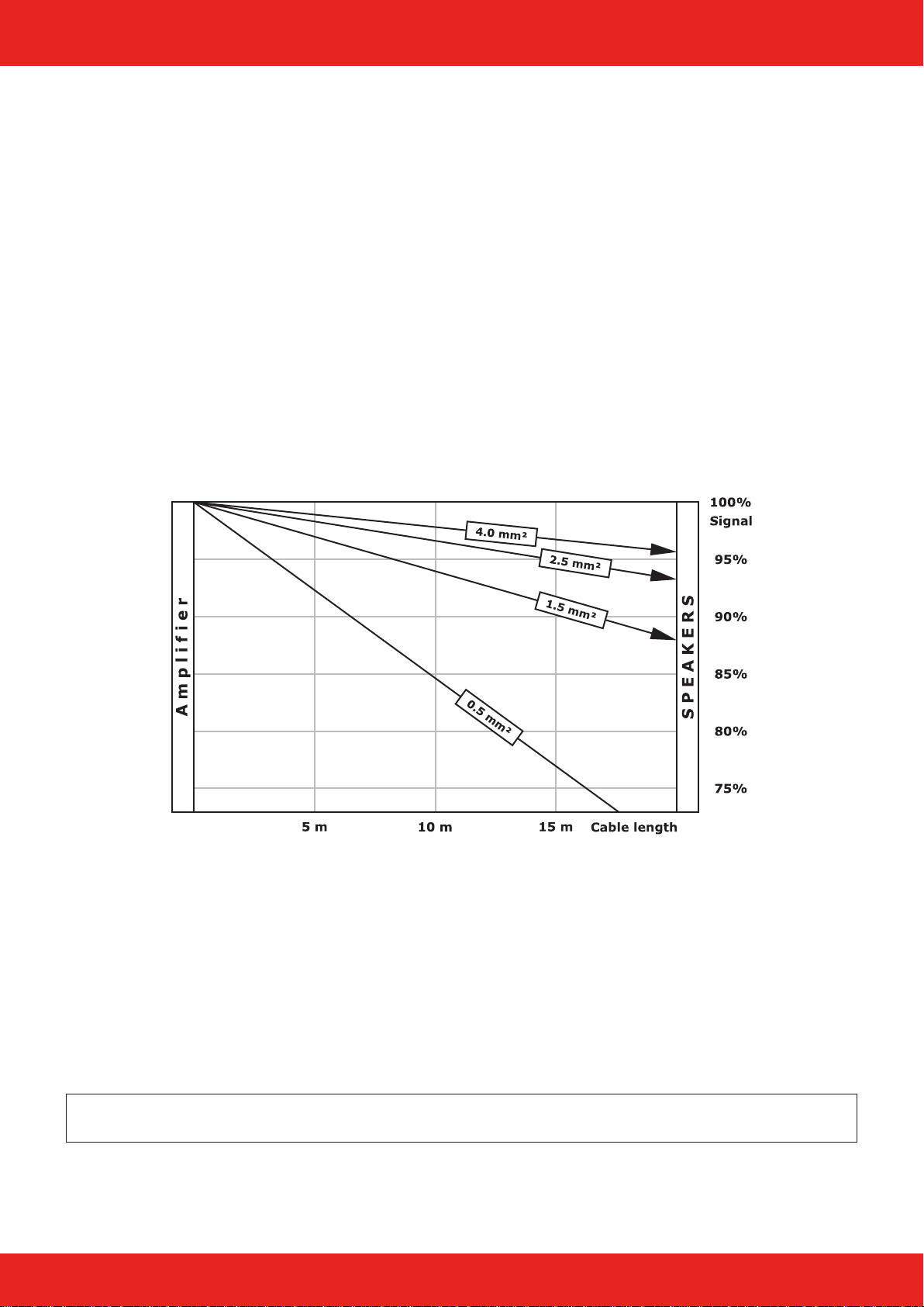
Voice-Acoustic recommends to use the available 4 x 4 mm² Speakon cables for mobile use.
We recommend wiring the basses with at least 4 mm² in installations. The cables of the tops in installations
must be suciently dimensioned according to impedance, power and cable length.
Simplied display without consideration of loudspeaker impedances
Operation
The LA-Stick 4x4 is exclusively intended for operation with Voice-Acoustic system electronics with internal DSP
controller: the HDSP power ampliers or powered by the free 800 W amplier channels of the self-powered sub-
woofers.
Make sure the appropriate preset has been selected before connecting the speaker to the system power amp or
self-powered subwoofer.
Using the wrong preset can damage parts of the loudspeaker.
Note: If the LA-Stick 4x4 is not operated on the intended Voice-Acoustic system electronics, the manufactu-
rer‘s warranty for the loudspeaker expires!
Introduction

Page 8 of 14Manual LA-Stick 4x4 - 2018-07 EN
Adjustment of the high frequency range to the array length
In the self-powered subwoofers, two dierent congurations are always available as presets for the LA-Stick
4x4. The settings dier only in the gain value of a high shelf lter (+3.00 dB or +5.00 dB) for adjusting the
high frequency range to the array length.
With increasing array length, the gain must be increased further.
Preset name: 2x LA4x4 XxxXXX (e.g. 2x LA4x4 Pav112) with one LA-Stick 4x4 per side:
High Shelf lter: Mid-band frequency 3.99 kHz, Quality 10.0 and Gain: 3.00 dB.
Type Freq Q Gain
High Shelf 3.99 kHz 10.0 3.00
Preset name: 4x LA4x4 XxxXXX (e.g. 4x LA4x4 Pav112) with two LA-Sticks 4x4 per side.
High Shelf lter: Mid-band frequency 3.99 kHz, Quality 10.0 and Gain: 5.00 dB.
Type Freq Q Gain
High Shelf 3.99 kHz 10.0 5.00
For the operation of three or four LA-Sticks 4x4 on top of each other per side, no standard setting can be set,
since the increase of the High-Shelf lter depends on the array length and the angle of inclination of the indi-
vidual elements to each other. The increase of the High-Shelf lter must therefore be measured or adjusted by
ear when operating three or four LA-Sticks 4x4 one above the other.
To keep the number of presets and speaker combinations in the HDSP ampliers manageable, only presets for
the operation of two LA-Sticks 4x4 per side with corresponding subwoofers are included.
4x LA4x4 XxxXXX (e.g. 4x LA4x4 Pav112).
If only one LA-Stick 4x4 per side is to be used with an HDSP amplier, the High-Shelf lter of the preset must
be lowered accordingly from +5.00 dB to +3.00 dB in Gain!
Working with LA-Stick 4x4

Page 9 of 14Manual LA-Stick 4x4 - 2018-07 EN
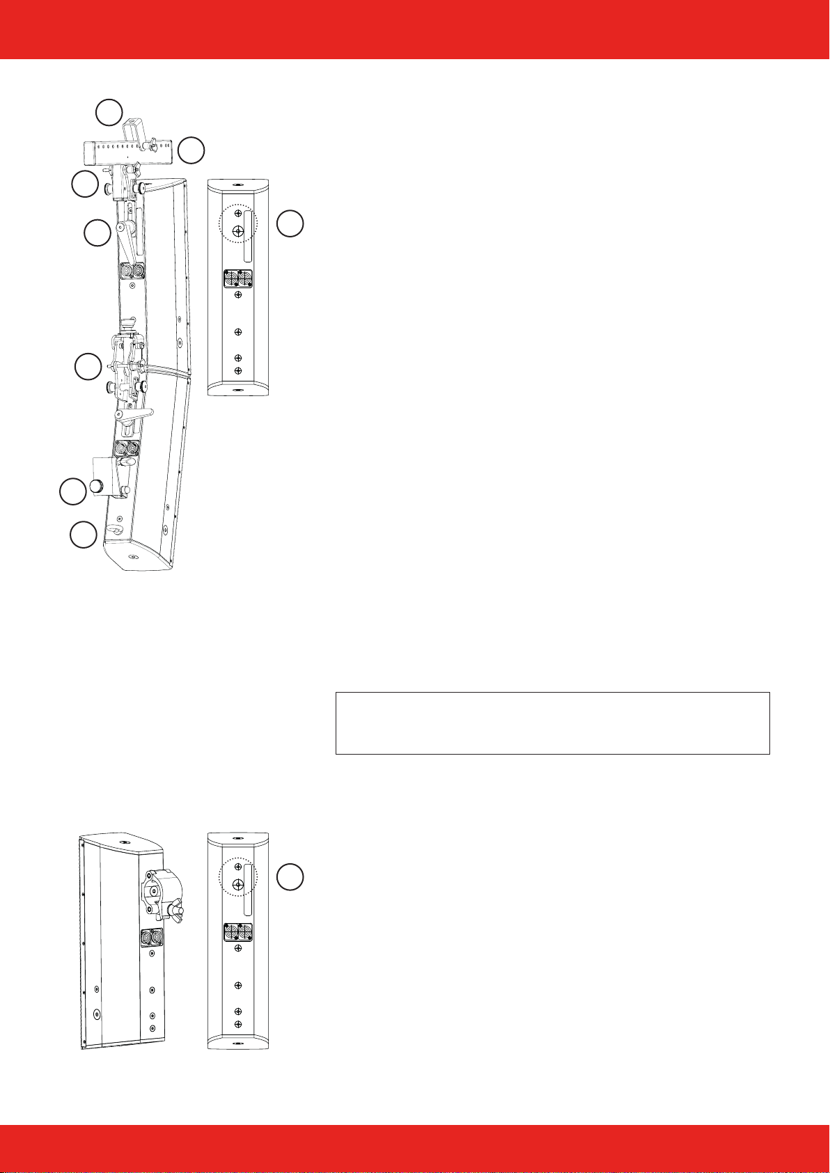
Mounting the spindle mechanics
12
8
1
9
11
6
7
5
2
3
4
14 15 16
13
17
10
To mount the angle mechanism on the back of the LA-Stick, the spindle (3) with locking pin holder (8) must be
released from the rotary knob (7). Hold the knob with one hand and turn the spindle out. Now you can screw
the rigid plate (2) onto the back of the LA-Stick (B) with two M6 x 30 mm screws (13). The two screws are
located on the back of the LA-Stick.
After you have mounted the rigid plate (2) on the back of the LA-Stick, screw the spindle (3) and the rotary
knob (7) together again. You can now connect the sliding plate (1) and xed plate (2) with the locking pin (9),
the locking pin holder (8) and the ball locking pin (11). Make sure that the ball locking pin is correctly inserted
and that both locking pins are engaged.
Use the M10 clamping lever (10) to x the sliding plate (1) to the bottom LA-Stick. To do this, remove the M10
x 25 mm hexagon socket screw on the back of the LA-Stick (A).
Separation of two LA-Stick 4x4
Loosen the M10 clamping lever (10) slightly and unlock the two locking bolts (9). Now remove the ball lock pin
(11) and pull the LA-Sticks apart. After the LA-Sticks have been disconnected, tighten the M10 clamping lever
(10) again rmly so that no whistling noises occur at the M10 thread point.
1. Sliding top spindle mechanics
2. Rigid plate spindle mechanics
3. Spindle with M6 thread
4. Retaining plate
5. Ball bearing
6. Ball bearing housing
7. Rotary knob with M6 threaded bolt
8. Locking pin holder with M6 internal thread
9. Locking pin with mounting ange
10. M10 clamping lever with axial bearing
11. Ball locking pin
12. Countersunk screw M4 x 5 mm
13. Countersunk screw with hexagon socket M6 x 30 mm
14. Socket head screw M6 x 20 mm
15. 6 mm washer
16. Self-locking nut M6
17. M5 x 8 mm pan-head screw with hexagon socket
Working with LA-Stick 4x4
A
B

Page 10 of 14Manual LA-Stick 4x4 - 2018-07 EN
Forming a Array
When mounting several LA sticks one below the other, please note
that for optimum coupling, the front edges of the box are always
tightly joined, regardless of whether you are working with the
spindle mechanics or the tilt adapters.
Adjust the angle with the spindle mechanics
1. Loosen the screw lever (A) on the bottom LA-Stick.
2. Turn the rotary knob (B) of the spindle mechanics on the top
LA-Stick until you have set the angle.
3. Push the LA-Sticks together at the front.
4. Tighten the screw lever (A) again.
5. Turn the rotary knob (B) a little bit so that some tension is
applied to the connection and nothing rattles.
Mounting the tilt adapter
There are three types with xed angles of 0°, 4° and 8°.
1. Remove the two M6 countersunk screws (B) in the top LA-Stick
and mount the tilt adapter rmly to the LA-Stick.
2. Remove the M6 and M10 countersunk screws (A) in the lower
one and mount the tilt adapter in the two slotted holes using
two cylinder head screws with washers. Use M10 and M6 x 30 -
50 mm screws.
3. Before you tighten the cylinder head screws (A), push both LA-
Sticks together so that the box edges are tightly joined at the
front for optimum coupling.
4. Tighten the cylinder head screws (A).
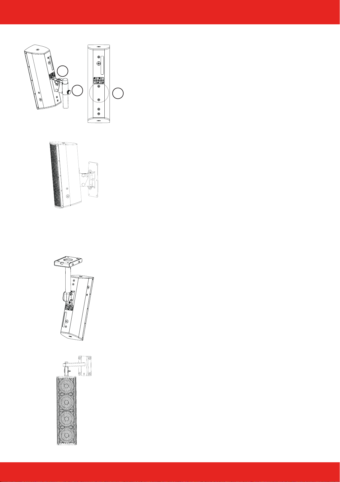
Mounting the U-bracket
With the U-bracket, up to four LA-Sticks can be used one above the
other, if it is fastened accordingly.
1. Remove the M10 and M6 countersunk screws (A) on both sides
of the LA-Stick.
2. Use the supplied M10 and M6 knurled screws (B) including pla-
stic washers to mount the U-bracket.
3. To protect the coatings, insert the plastic washers between the
knurled screw, U-bracket and LA-Stick.
Note: The U-bracket is only intended for vertical mounting, it is
not suitable as a ceiling bracket, as the grid is not intended for
angling in this position!
A
B
A
B
Working with LA-Stick 4x4
B
A
Page 11 of 14Manual LA-Stick 4x4 - 2018-07 EN
LA-Stick 4x4 in ight operation
Using ight mechanics, up to four LA sticks can be own under each
other on ceilings and trusses.
Assembly and alignment of the ight mechanics
1. Use the M10 clamping lever (4) to attach the ight mechanic to
the LA-Stick. To do this, rst remove the M10 x 25 mm hexa-
gon socket screw on the back of the LA-Stick (A).
2. Connect the two parts of the ight mechanics with each other
with the aid of the locking pins and the ball locking pin (3).
3. The small U-bracket (1) can be mounted directly on the ceiling,
or e.g. on the universal suspension device for ight mechanics
or the self lock clamp.
4. Align the ight mechanics by xing the U-bracket on the upper
hole rail (2) with the ball locking pin. How the center of gravity
behaves depends on the number of LA-Sticks attached to the
ight mechanics.
Safety points in ight operations
1. You can use any free M6 threaded point on the back for an M6
x 30 mm (7) eyelet.
2. If several LA-Sticks are connected to each other with the spind-
le mechanics, you can pass the safety catch rope under the ball
locking pin (5) and attach it to the safety point of the bottom
LA-Stick (7). The top LA-Stick is then secured.
3. Users who frequently switch between tripod and ight operati-
on can also use the tiltable stand adapter (6) as a safety point
with the aid of a 6 mm chain link after you have carried out the
safety catch rope under the ball locking pin (5).
Note: The M10 threaded points at the top and bottom of the
housing must not be used as securing points. In case of over-
stress, the bottom or cover of the housing may break o!
Flight operation at truss clamp
max. load: Four LA-Sticks with spindle mechanics.
1. Remove the M10 countersunk screw (A) and mount the cross-
head clamp. The clamp should be provided for countersunk
screws so that the crosshead clamp can be tightened rmly in
the desired position.
We recommend it:
■Ultralite Half Coupler M10, black, Code: KCP-831B
■Ultralite Half Coupler M10, silver, Code: KCP-831
Working with LA-Stick 4x4
1
2
4
3
5
6
7
A
A
Page 12 of 14Manual LA-Stick 4x4 - 2018-07 EN
A
BC
Mounting the tiltable stand adapter
max. load: Two LA-Sticks with spindle mechanics.
1. Remove the two M6 countersunk screws (C) and mount the
adapter rmly to the LA-Stick.
2. Tighten clamping screw (B) to secure the position of the ad-
apter on the stand or spacer rod. We recommend: Tripods or
rods with „Ring Lock“.
3. To adjust the inclination of the adapter, loosen the wing nut (A)
and then tighten it again.
Mounting the tilting and swivelling wall bracket
max. load: Four LA-Sticks with spindle mechanics.
1. When mounting the wall bracket to the wall, follow the manu-
facturer‘s operating instructions.
2. Remove the two M6 countersunk screws (C) and attach the
swivel bracket of the wall bracket rmly to the LA-Stick.
3. Hang the swivel bracket (with mounted loudspeaker) into the
wall bracket.
4. Screw parts together using the lower carriage bolt, washer and
lock nut. Adjust the inclination on the scale and retighten the
upper screw connection.
Mounting the ceiling bracket
max. load: Four LA-Sticks with spindle mechanics.
1. When mounting the ceiling plate of the bracket to ceilings, fol-
low the manufacturer‘s operating instructions.
2. Remove the two M6 countersunk screws (C).
3. Fix the ceiling bracket to the LA-Stick with two M6 hexagon
socket head screws and washers.
4. Attach ceiling bracket with LA-Stick to the ceiling panel and set
the desired inclination and direction.
Mounting the wall bracket
max. load: One LA-Stick. If overloaded, the housing cover may
break o!
1. When mounting the wall bracket to the wall, follow the manu-
facturer‘s operating instructions.
2. Remove the M10 countersunk screw on the top of the LA-Stick
and mount the rotary and swivel axis there.
3. Attach the rotary and swivel axis to the wall bracket with
LA-Stick and set the desired inclination and direction.
Working with LA-Stick 4x4

Page 13 of 14Manual LA-Stick 4x4 - 2018-07 EN
Overview Accessories
U-Bracket for LA-Stick 4x4 (Art.-Nr. 400441001)
U-Bracket for LA-Stick 4x4, white with stainless steel knurled screws (Art.-Nr. 400441002)
U-Bracket for LA-Stick 4x4, special color with stainless steel knurled screws (Art.-Nr. 400441009)
Spindle mechanics for LA-Stick 4x4 (Art.-Nr. 400443001)
Tiltable stand adapter, 30° tiltable for LA-Stick 4x4 (Art.-Nr. 999919780)
0° Tilt adapter as an alternative to spindle mechanics (Art.-Nr. 400445001)
4° Tilt adapter as an alternative to spindle mechanics (Art.-Nr. 400445041)
8° Tilt adapter as an alternative to spindle mechanics (Art.-Nr. 400445081)
Flight mechanics for LA-Stick 4x4 (Art.-Nr. 400444001)
Wall bracket for hanging on the M10 thread of the upper side of the housing (Art.-Nr. 999908131)
Carrying bag for up to 2 x LA-Stick 4x4 (Art.-Nr. 500442000)
Heavy-Duty Flightcase für bis zu 4 x LA-Stick 4x4 (Art.-Nr. 500443000)
Universal suspension arrangement for ight mechanics (Art.-Nr. 409992001)
Speaker ceiling mount (Art.-Nr. 999924496)
Speaker ceiling mount, white (Art.-Nr. 999224496)
Wall bracket, slewable and 30° tiltable (Art.-Nr. 999924481)
Wall bracket, slewable and 30° tiltable, white (Art.-Nr. 999224481)
Safety 6/1000 mm (Art.-Nr. 999963100)
Self lock clamp for pipe 48-51mm, 30mm wide, max. 250 kg (Art.-Nr. 999950731)
Working with LA-Stick 4x4

Page 14 of 14Manual LA-Stick 4x4 - 2018-07 EN
Manufacturer‘s declaration
Imprint
© SRV Licht- & Tonanlagen, all rights reserved.
All specications in this manual are based on information available
at the time of publishing for the features and safety guidelines of
the described products. Technical specications, measurements,
weights and properties are not guaranteed.
The manufacturer reserves the right to make technical modications
according to legal regulations stipulating the continual improvement
of product features. For the safe operation of the unit, this manual
and all other required information must be available to all users at
the time of assembly and disassembly of the unit, and during opera-
tion. Assemble or operate the unit only after reading and understan-
ding this manual, and keeping it at hand at all times at the site.
We are happy to receive your suggestions and proposals for the
enhancement of this manual.
Please send us your ideas to the following address:
SRV Licht- & Tonanlagen - Voice-Acoustic Headquarters
Brocksfeld 3
D-27313 Dörverden
Tel.: + 49 (0) 4234 942 777
E-Mail: [email protected]
Table of contents
Other Voice-Acoustic Speakers manuals

Voice-Acoustic
Voice-Acoustic VENIA-8sp DDA User manual

Voice-Acoustic
Voice-Acoustic Modular-10 User manual

Voice-Acoustic
Voice-Acoustic Alea-4 User manual

Voice-Acoustic
Voice-Acoustic Modular-15 User manual

Voice-Acoustic
Voice-Acoustic Modular-15sp User manual

Voice-Acoustic
Voice-Acoustic Score-5 User manual

Voice-Acoustic
Voice-Acoustic Score-8 User manual

Voice-Acoustic
Voice-Acoustic VENIA-6sp DDA User manual


