Voice-Acoustic Score-5 User manual

Score-5
Multifunctional loudspeaker
Manual

Herzlichen Dank,
dass Sie ein Voice-Acoustic Produkt gekauft haben.
Seit dem Jahr 2006 entwickeln wir unsere Produkte
in der Überzeugung, dass es auf die Details ankommt.
Wir wünschen Ihnen viel Freude mit diesem Produkt.
Thank you very much,
for purchasing a Voice-Acoustic product.
Since 2006 we have been developing our
products in the rm belief that details matter.
May we wish you a lot of pleasure with this product.
Muchas gracias
por haber comprado un producto de Voice-Acoustic.
Desdel año 2006 estamos desarrollando nuestros productos
estando convencidos, que son los detalles que cuentan.
Le(s) deseamos mucha alegría usando este producto.
Merci beaucoup
d´avoir acheté un produit Voice-Acoustic.
Depuis 2006, nous développons des produits
avec la ferme conviction que les détails comptent.
Nous vous souhaitons beaucoup de plaisir à utiliser ce produit.

Contents
Introduction
General Safety Instructions 4
Care 4
Transport and storage 4
Warranty 4
Components 5
Technical data 6
Connections 6
Setup 7
Connecting cables 7
Operation 7
Working with Score-5
Adaptation to amplier electronics of other manufacturers 8
Mounting the L-bracket 9
Adjust the tilt 9
Flight operation with L-bracket on truss 9
Installations with truss clamp adapter 10
Flight operation with suspension arrangement 10
Mounting the tilting and swivelling wall bracket 11
Mounting the ceiling bracket 11
Flight operation at truss clamp 11
Monitoring with Score-5 11
Overview Accessories 12
Manufacturer‘s declaration
Imprint 13

Page 4 of 13Manual Score-5 - 2018-07 EN
General Safety Instructions:
Loudspeakers produce a static magnetic eld even if they are not connected or are not in use. Therefore make
sure when erecting and transporting loudspeakers that they are nowhere near equipment and objects which
may be impaired or damaged by an external magnetic eld. Persons with cardiac pacemakers must maintain a
safe distance.
The minimum recommended safety clearance is 1 m.
Never stand in the immediate vicinity of loudspeakers driven at a high level. Professional loudspeaker systems
are capable of causing a sound pressure level detrimental to human health. Seemingly non-critical sound levels
(from approx. 90 dB SPL) can cause hearing damage if people are exposed to it over a long period.
All connected cables must be laid in such a way that they cannot be crushed by objects and that nobody can
step on them! Replace damaged cables immediately and do not use them!
Use only accessory parts specied by Voice-Acoustic or original accessory parts from Voice-Acoustic. Check all
cabinets and accessories regularly for wear and replace them if necessary.
Do not set up the loudspeakers in places where they are permanently exposed to moisture, dust, dirt or direct
sunlight.
Care
Wipe the surface of loudspeakers only with a damp cloth and pure water. In case of heavy pollution, repeat the
above procedure several times if necessary. Do not use any chemical additives or aggressive detergents, as
these may harm and damage the surfaces.
Transport and storage
When transporting and storing the unit, it is important to ensure that the surface and front grill of the loudspe-
aker are not damaged. Moisture can penetrate through exposed wood surfaces and cause the wood to swell.
A bent or broken front grill will no longer adequately protect the sensitive speaker membranes. In addition,
appreciable dust deposits may considerably impair the functionality of a loudspeaker membrane. For this rea-
son, the loudspeakers should be transported and stored in a safe, careful, dry and largely dust-free manner.
The following accessory parts for transport and storage are available from Voice-Acoustic:
■Carrying bag for up to 2 x Score-5 (Art.-Nr. 505002000)
■Heavy duty ightcase for up to 4 x Score-5 (Art.-Nr. 505003000)
Note: The original packaging is unsuitable as permanent storage and transport packaging!
Warranty
The warranty period is 24 months from date of delivery.
On our choice we will eliminate any lack of conformity with repair or with replacement of the faulty goods. The
place of performance for warranty services is Voice-Acoustic headquarters in Dörverden. In case of remedy of
defects, the buyer shall bear all costs resulting from transportation of the goods to Voice-Acoustic headquarters
in Dörverden.
The ordering party is not entitled to remedy the defect by itself or to organise a replacement and to charge
such activities to Voice-Acoustic. In case of self remedy by the ordering party the warranty given by Voice-
Acoustic becomes void.
Warranty doesn’t apply to parts of wear and tear, such as threaded points, Camlock connectors and
the SpeakON®connectors.
Introduction
Page 5 of 13Manual Score-5 - 2018-07 EN
Introduction
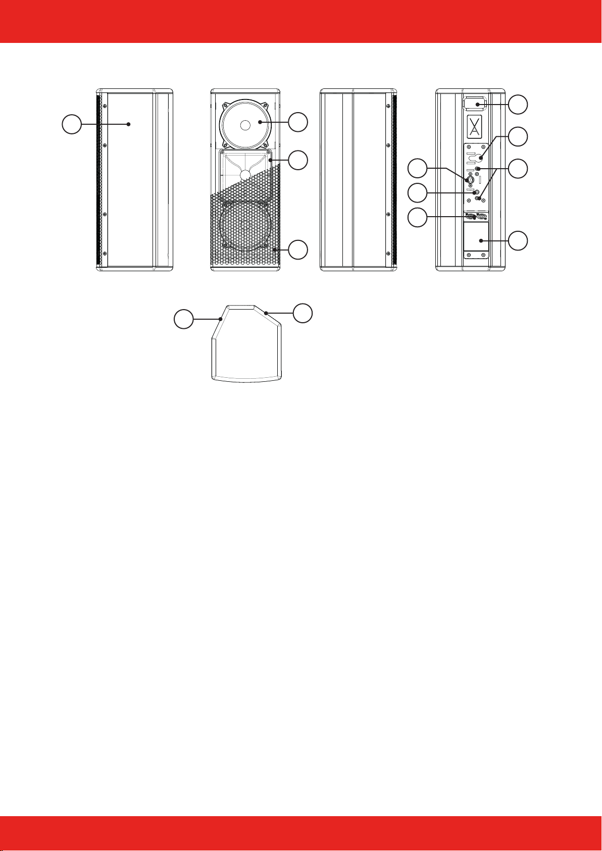
Components
1. 15 and 12 mm multiplex cabinet, Warnex textured paint nish
2. Monitor slant 25°
3. 5“ Neodym woofer
4. 1“ Ferrit compression driver with horn 70° x 55°
5. Front grille 1 mm with 5 mm acoustic foam
6. Monitor slant 55°
7. Camlock for tool-free bracket mounting
8. M8 threaded points for mounting accessories, e.g. truss clamp
9. Connector panel with two SpeakON®connectors
10. Rear recessed grip
11. Safety point for safety rope with Single-Stud
12. M6 threaded points for mounting a wall or ceiling bracket
13. Type plate with serial number
1
10
11
12
13
5
3
7
8
9
26
4
Table of contents
Other Voice-Acoustic Speakers manuals

Voice-Acoustic
Voice-Acoustic LA-Stick 4x4 User manual

Voice-Acoustic
Voice-Acoustic VENIA-6sp DDA User manual

Voice-Acoustic
Voice-Acoustic Modular-10 User manual

Voice-Acoustic
Voice-Acoustic Alea-4 User manual

Voice-Acoustic
Voice-Acoustic Modular-15sp User manual

Voice-Acoustic
Voice-Acoustic VENIA-8sp DDA User manual

Voice-Acoustic
Voice-Acoustic Score-8 User manual

Voice-Acoustic
Voice-Acoustic Modular-15 User manual


