Voice-Acoustic Score-8 User manual

Score-8
Multifunctional loudspeaker
Manual

Herzlichen Dank,
dass Sie ein Voice-Acoustic Produkt gekauft haben.
Seit dem Jahr 2006 entwickeln wir unsere Produkte
in der Überzeugung, dass es auf die Details ankommt.
Wir wünschen Ihnen viel Freude mit diesem Produkt.
Thank you very much,
for purchasing a Voice-Acoustic product.
Since 2006 we have been developing our
products in the rm belief that details matter.
May we wish you a lot of pleasure with this product.
Muchas gracias
por haber comprado un producto de Voice-Acoustic.
Desdel año 2006 estamos desarrollando nuestros productos
estando convencidos, que son los detalles que cuentan.
Le(s) deseamos mucha alegría usando este producto.
Merci beaucoup
d´avoir acheté un produit Voice-Acoustic.
Depuis 2006, nous développons des produits
avec la ferme conviction que les détails comptent.
Nous vous souhaitons beaucoup de plaisir à utiliser ce produit.

Contents
Introduction
General Safety Instructions 4
Care 4
Transport and storage 4
Warranty 4
Components 5
Technical data 6
Connections 6
Setup 7
Connecting cables 7
Operation 7
Working with Score-8
Mounting the L-bracket 8
Adjust the tilt 8
Flight operation with L-bracket on truss 8
Installations with truss clamp adapter 9
Mounting the tilting and swivelling wall bracket 10
Mounting the U-bracket 10
Mounting the C-bracket 10
Monitoring with Score-8 11
Easyy mechanics 11
Installations with Easyy mechanics 11
Adjusting the inclination with the Easyy mechanic 12
Overview Accessories 13
Manufacturer‘s declaration
Imprint 15

Page 4 of 15Manual Score-8 - 2021-10 EN
General Safety Instructions:
Loudspeakers produce a static magnetic eld even if they are not connected or are not in use. Therefore make
sure when erecting and transporting loudspeakers that they are nowhere near equipment and objects which
may be impaired or damaged by an external magnetic eld. Persons with cardiac pacemakers must maintain a
safe distance.
The minimum recommended safety clearance is 1 m.
Never stand in the immediate vicinity of loudspeakers driven at a high level. Professional loudspeaker systems
are capable of causing a sound pressure level detrimental to human health. Seemingly non-critical sound levels
(from approx. 90 dB SPL) can cause hearing damage if people are exposed to it over a long period.
All connected cables must be laid in such a way that they cannot be crushed by objects and that nobody can
step on them! Replace damaged cables immediately and do not use them!
Use only accessory parts specied by Voice-Acoustic or original accessory parts from Voice-Acoustic. Check all
cabinets and accessories regularly for wear and replace them if necessary.
Do not set up the loudspeakers in places where they are permanently exposed to moisture, dust, dirt or direct
sunlight.
Care
Wipe the surface of loudspeakers only with a damp cloth and pure water. In case of heavy pollution, repeat the
above procedure several times if necessary. Do not use any chemical additives or aggressive detergents, as
these may harm and damage the surfaces.
Transport and storage
When transporting and storing the unit, it is important to ensure that the surface and front grill of the loudspe-
aker are not damaged. Moisture can penetrate through exposed wood surfaces and cause the wood to swell.
A bent or broken front grill will no longer adequately protect the sensitive speaker membranes. In addition,
appreciable dust deposits may considerably impair the functionality of a loudspeaker membrane. For this rea-
son, the loudspeakers should be transported and stored in a safe, careful, dry and largely dust-free manner.
The following accessory parts for transport and storage are available from Voice-Acoustic:
■Transport and rain cover for Score-8 (Art.-Nr. 508001000)
Note: The original packaging is unsuitable as permanent storage and transport packaging!
Warranty
The warranty period is 24 months from date of delivery.
On our choice we will eliminate any lack of conformity with repair or with replacement of the faulty goods. The
place of performance for warranty services is Voice-Acoustic headquarters in Dörverden. In case of remedy of
defects, the buyer shall bear all costs resulting from transportation of the goods to Voice-Acoustic headquarters
in Dörverden.
The ordering party is not entitled to remedy the defect by itself or to organise a replacement and to charge
such activities to Voice-Acoustic. In case of self remedy by the ordering party the warranty given by Voice-
Acoustic becomes void.
Warranty doesn’t apply to parts of wear and tear, such as threaded points, Camlock connectors and
the SpeakON®connectors.
Introduction
Page 5 of 15Manual Score-8 - 2021-10 EN
Introduction
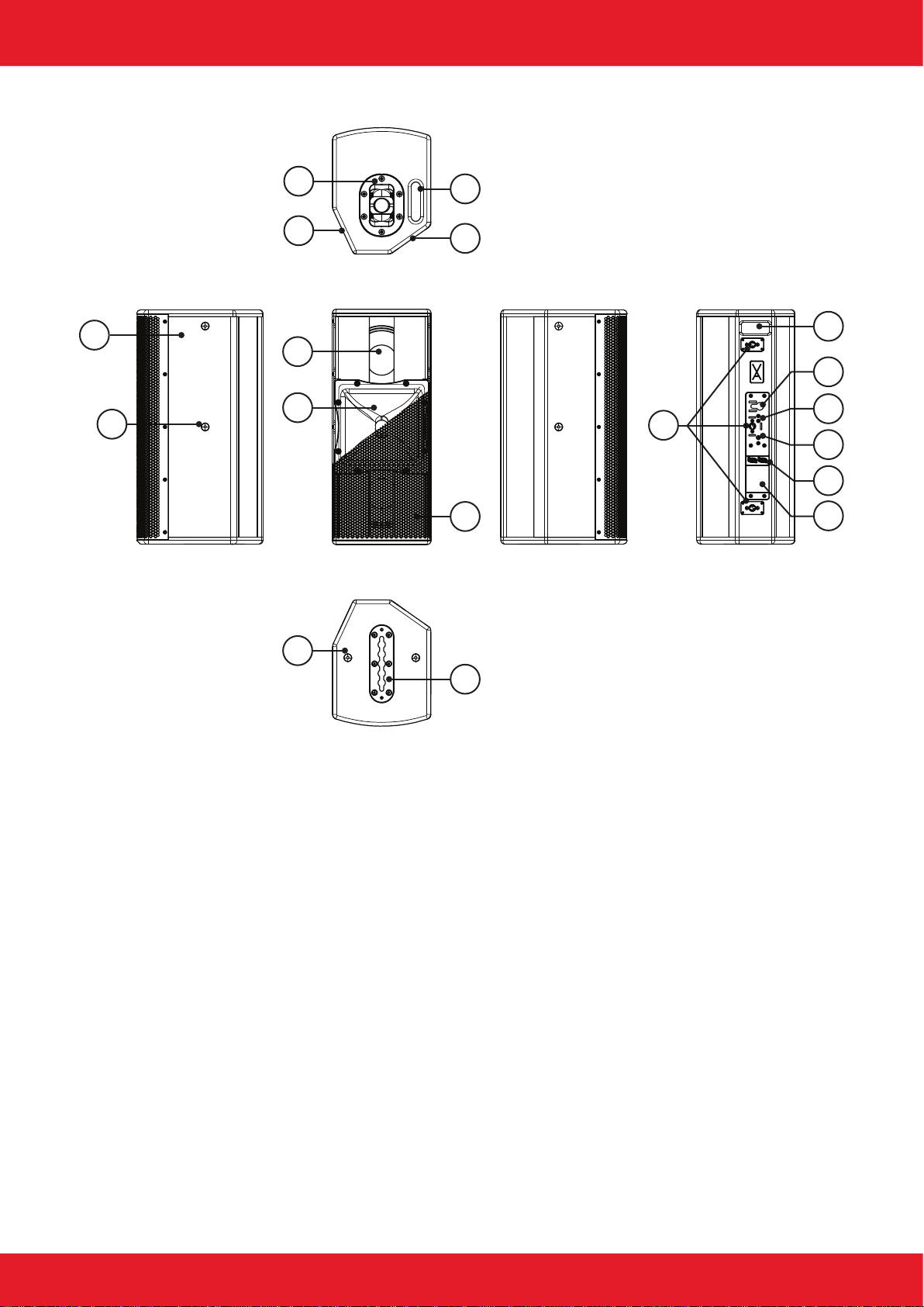
Components
3
4
5
6
7
13
1
2
10
11
8
9
12
14
15
16
17
18
1. 15 and 12 mm multiplex cabinet, Surface with moisture resistant polyurea coating
2. 2 x M10 mounting point for U-bracket
3. Tilting pole socket +/- 18°
4. Monitor slant 25°
5. 8“ Neodym woofer
6. 1,4“ Neodym compression driver with horn 90° x 40° or 60° x 40°
7. 8 x M10 mounting points with internal steel brackets
8. Recessed grip on the underside
9. Monitor slant 55°
10. Front grille 1 mm with 5 mm acoustic foam
11. Easyy ying track for vertical suspension
12. Camlock for tool-free bracket mounting
13. Rear recessed grip top
14. Safety point for safety rope with Single-Stud
15. M6 threaded points for mounting a wall or ceiling bracket
16. M8 threaded points for mounting accessories, e.g. truss clamp
17. Connector panel with two SpeakON® connectors
18. Type plate with serial number
Page 6 of 15Manual Score-8 - 2021-10 EN
Introduction
Technical data
Components 2 x 8“ Neodym woofer with 2,5“ voice coil
1 x 1,4“ Neodym compression driver with 2,4“ voice coil
Frequency response 65 Hz - 19 kHz (- 10 dB)
78 Hz - 17,3 kHz (+/- 3 dB)
Coverage range (h x v) 90° x 40° or 60° x 40°
Monitor angles 55° and 25°, 90° for Nearll
Powerhandling 500 W AES / 1.000 W program / 2.000 W peak at 4 Ω
Sound pressure 130 dB SPL AES / 133 dB SPL program / 136 dB SPL peak
Dimensions / Weight 625 (h) x 262 (w) x 337 (d) mm / 19,6 kg
Finish Polyurea coating in RAL 9005, Special colors in Warnex textured paint
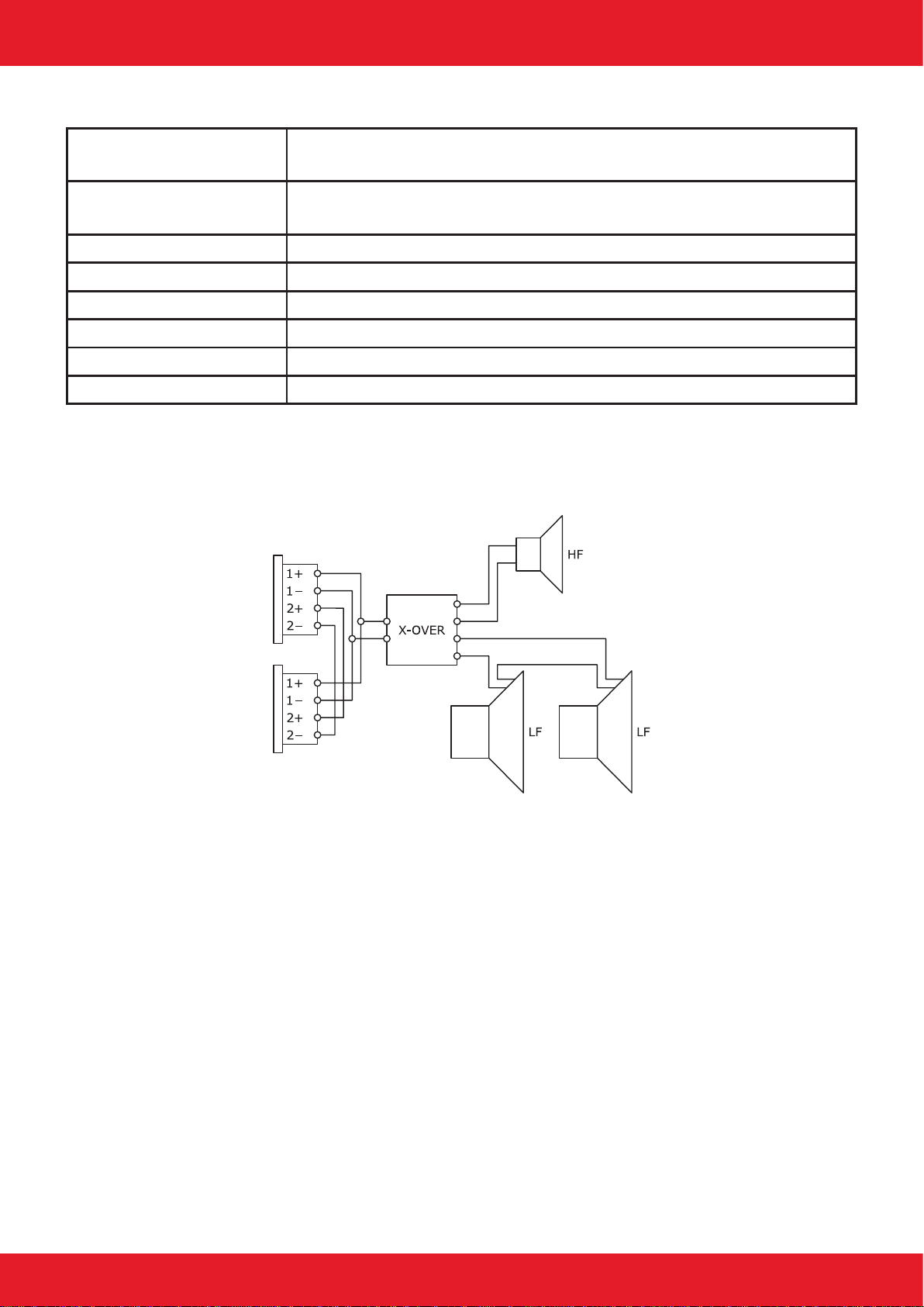
Connections
The speaker has two loop-through Neutrik NL4 SpeakON®IN/OUT connectors. They use the 1+/1- connection
pins. Additional loudspeakers can be looped through via the second connector.
Page 7 of 15Manual Score-8 - 2021-10 EN
Setup
The Score-8 loudspeaker is designed for vertical and horizontal operation. A variety of accessories is available
from Voice-Acoustic to securely attach the loudspeaker safely on tripods, distance rods or hanging it from on
trusses, ceilings and walls. Ensure that the loudspeakers are securely attached to prevent personal injury and
damage of property.
Connecting cables
When connecting the cables to the loudspeaker, ensure that the polarity (+/-) and pin assignment (1/2) is
correct. Incorrect connection results in a signicant change in the loudspeaker sound characteristics and may
damage the compression driver.
The two connection sockets on the back of the loudspeaker can be used to link multiple loudspeakers on a
single amplier. Note that parallel connection reduces the total impedance (Ω) seen by the amplier. The total
impedance of loudspeakers connected in parallel must not drop below the minimum operating impedance of the
amplier.
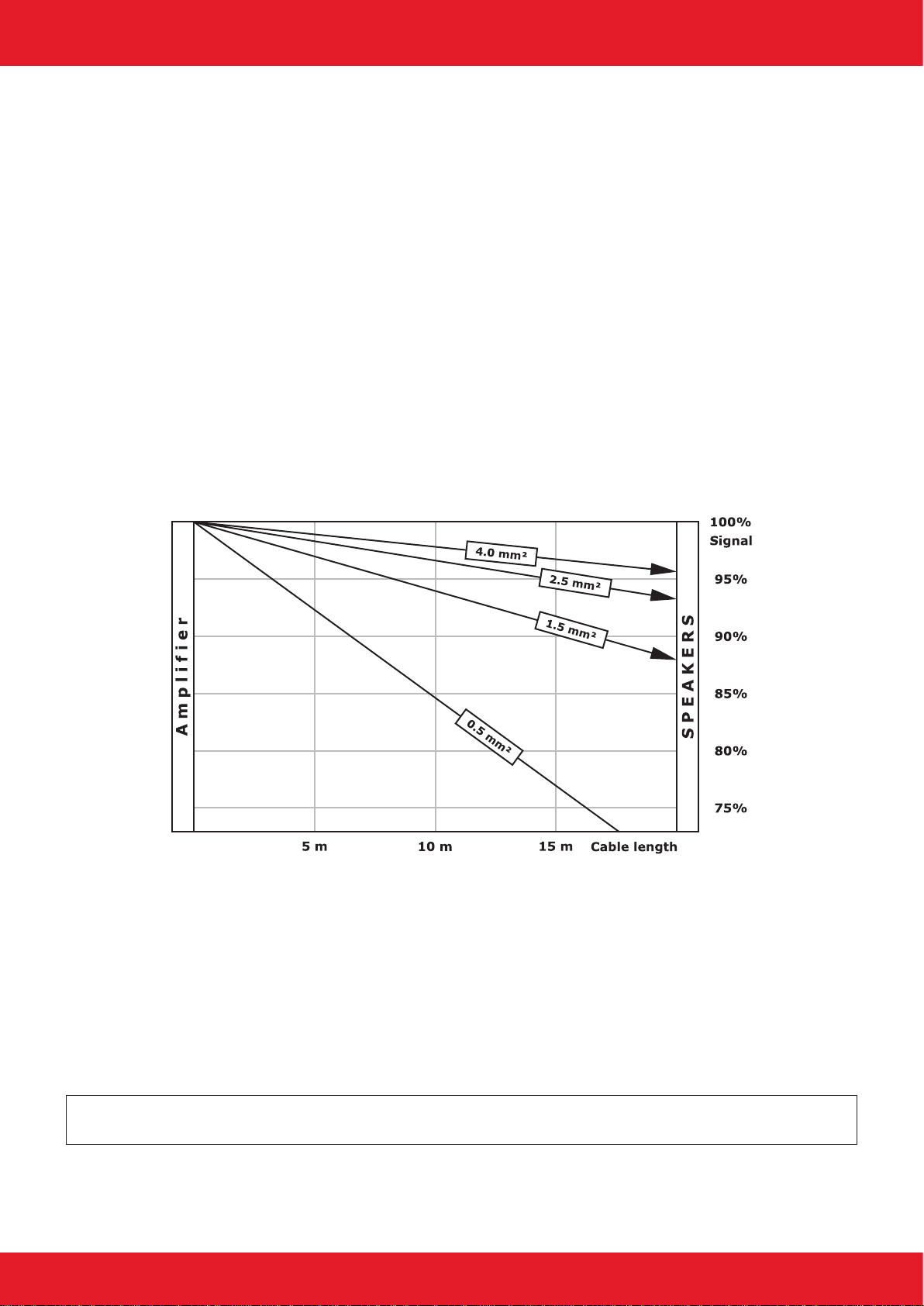
Voice-Acoustic recommends to use the available 4 x 4 mm² Speakon cables for mobile use.
We recommend wiring the basses with at least 4 mm² in installations. The cables of the tops in installations
must be suciently dimensioned according to impedance, power and cable length.
Simplied display without consideration of loudspeaker impedances
Operation
The Score-8 is exclusively intended for operation with Voice-Acoustic system electronics with internal DSP cont-
roller: the HDSP power ampliers or powered by the free 800 W amplier channels of the self-powered subwoo-
fers.
When working with the Voice-Acoustic system electronics, make sure the appropriate preset has been selected
before connecting the loudspeaker to the system power amplier or self-powered subwoofer. Using the wrong
preset can damage parts of the loudspeaker.
Note: If the Score-8 is not operated on the intended Voice-Acoustic system electronics, the manufacturer‘s
warranty for the loudspeaker expires!
Working with Score-8
Page 8 of 15Manual Score-8 - 2021-10 EN
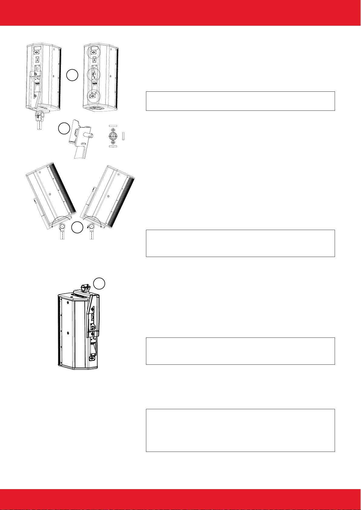
Mounting the L-bracket
1. To hold the L-bracket in a desired position, select one of the
xing points (1) to (2).
2. Insert both camlock connectors (A) of the L-bracket into the
holding cam (B) and turn it around until it engages.
Note: The Camlock connector must be turned and locked correct-
ly to prevent the loudspeaker from falling o!
Fixing points:
(1) L-bracket bottom, Score-8 in tripod mode
(2) L-bracket top, Score-8 in ight operations
(3) L-bracket sideways, not possible with one Camlock connection!
Adjust the tilt
Mount the truss clamp to the L-bracket in such a way that the wing
nut (C) does not hinder tilting.
1. Secure the loudspeaker against tipping by hand.
2. Slightly unscrew the wing nut (C) on the clamp.
3. Adjust the tilt.
4. Tighten the wing nut (C) again to x it.
Note: The wing nut of the clamp must always be tightened,
otherwise there is a risk that it will come loose due to vibrations
and the loudspeaker could tilt uncontrollably!
Flight operation with L-bracket on truss
Without truss clamp adapter, the L-bracket with its clamp can be
used on all common truss with 48 - 51 mm belt tubes. The three
xing points are also used here.
Fixing points:
(1) Connection panel at the top (cables are routed upwards)
(2) Connection panel at the bottom (cables are routed downwards)
1.
Note: If you use the xing point (3) for ight operation, you
must rst insert the single-stud tting into the intended securing
point. Since then the L-bracket sits in front of it!
Hang the loudspeaker and L-bracket with clamp into the truss.
2. Adjusting the tilt.
3. Tighten the wing nut (C) again to x it.
Note: If speakers are suspended with detachable connections,
they require a second, independent, non-combustible connection
(secondary fuse), usually an appropriately dimensioned steel sa-
fety rope. Please observe the currently applicable standards and
regulations.
Working with Score-8
1
3
2
B
A
C
C
B

Page 9 of 15Manual Score-8 - 2021-10 EN
Installations with truss clamp adapter
Attach the truss clamp adapter to the wall, ceiling or oor using
suitable xing materials.
Installation with truss clamp at the rear and adapter horizontally on
the wall, or upside down on the ceiling.
1. Use an M8 x 15 mm threaded screw and washer to mount
the truss clamp to the M8 threaded point on the rear of the
loudspeaker.
2. Hang the loudspeaker into the adapter.
3. Adjust the tilt.
4. Tighten the wing nut again to x it.
Installation with L-bracket with truss clamp and adapter on the cei-
ling or standing.
1. Hang loudspeakers with L-bracket into the adapter.
2. Adjust the tilt.
3. Tighten the wing nut again to x it.
Installation using universal suspension device for ight mechanisms,
L-bracket with truss clamp and adapter on high ceilings.
1. Mount the truss clamp at point (A) of the L-bracket.
2. Attach the truss clamp adapter to the universal suspension
device (B) using suitable fastening material.
3. Hang loudspeakers with L-bracket into the adapter.
4. Adjust the tilt.
5. Tighten the wing nut again to x it.
Working with Score-8
A
B

Page 10 of 15Manual Score-8 - 2021-10 EN
Mounting the tilting and swivelling wall bracket
1. When mounting the bracket to the wall, follow the manufactu-
rer‘s operating instructions.
2. Remove the swivel bracket on the wall bracket.
3. Use two M6 x 15 mm threaded screws and washers to x the
swivel bracket to the two M6 threaded points (A) on the rear of
the loudspeaker.
4. Hang the swivel bracket (with mounted speaker) into the bra-
cket attached to the wall.
5. Screw parts together using the lower carriage bolt, washer and
lock nut.
6. Adjust and x the tilt.
Mounting the U-bracket
1. Remove the M10 countersunk screws (A) on both sides of the
Score-8.
2. Use the supplied M10 hexagon head screws (B) including pla-
stic washers to mount the U-bracket.
3. To protect the coatings, place the plastic discs between the
hexagon head screw, U-bracket and Score-8.
Mounting the C-bracket
The bracket consists of two dierent brackets and connected by
two M8 screws.
1. Mount the C-bracket (B) with two M6, one M8 x 15 mm threa-
ded screw and washers rmly to the three threaded points (A)
on the rear of the speaker.
2. Observe the recess (C) for the cable feed on the bracket.
3. Mount the second bracket (D) horizontally or vertically to the
wall using the appropriate xing material.
4. Connect the brackets with the two M8 screws (E).
5. Adjust and x the tilt or direction.
Note: Since the cabinet wall lies benneath the rear threaded
points, the threaded screws must not exceed 15 mm in length!
Working with Score-8
A
A
G
A
B
F
DE
Front
Page 11 of 15Manual Score-8 - 2021-10 EN
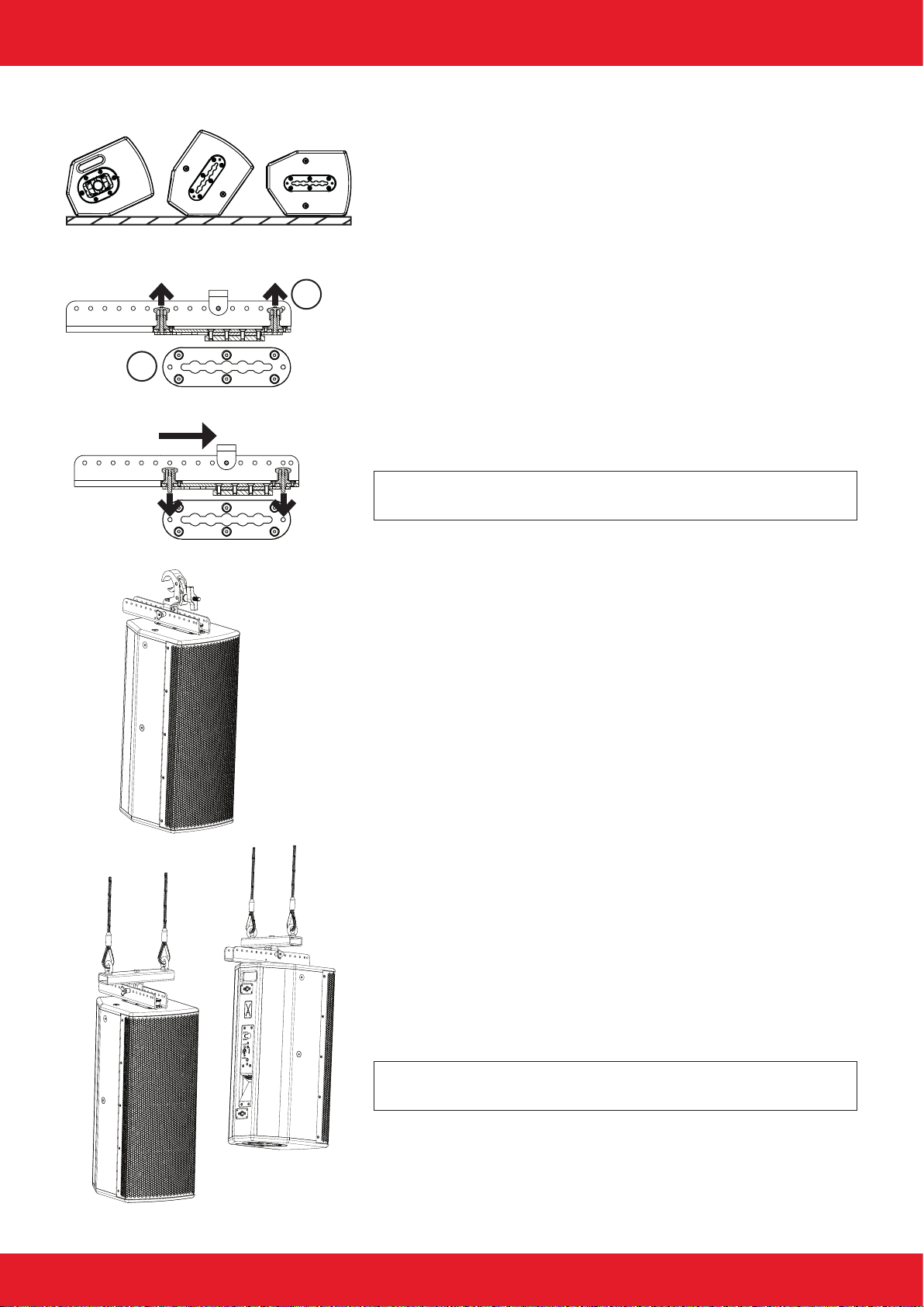
Monitoring with Score-8
For monitor operation, two housing slopes, 25° and 55°, are avai-
lable for Score-8. At 90°, due to the side wall running to the bae
and at design, the Score-8 is ideal as an inconspicuous nearll on
the front edge of the stage or installed in staircases.
Easyy mechanics
Tool-less ight mechanism for clicking in and exact alignment of the
loudspeaker in the horizontal and vertical axis.
1. Pull the two locking bolts (A) upwards and let them engage by
turning them slightly.
2. Insert the Easyy mechanics into the ying track (B).
3. Slide the mechanics backwards as far as it will go.
4. Let the two locking bolts snap into the intended holes on the
ying track.
Note: Notice that the two locking pins (A) are engaged to pre-
vent the Easyy-Mechanics from slipping out.
Installations with Easyy mechanics
Installation with self-lock clamp (C) on trusses.
1. Mount the self-lock clamp to the Easyy mechanics using an
M10 threaded screw and lock nut.
2. Hang the clamp and holder into the mechanics using ball lock
bolts.
3. Hang the loudspeaker into the truss.
4. Adjust the inclination by xing the holder on the top hole rail
with the ball locking pin.
Installation with universal suspension arrangement for ight mecha-
nics (D) on high ceilings
1. Mount the universal suspension arrangement for ight mecha-
nics with an M10 threaded screw and lock nut to the mounting
of the Easyy mechanics.
2. Hang the suspension device and holder into the mechanics
using ball locking bolts.
3. Hang the loudspeaker into the installed chains.
4. Adjust the inclination by xing the holder on the top hole rail
with the ball locking pin.
Note: The inclination depends on the hole in which you x the
Easyy mount on the hole rail!
Working with Score-8
25° 55° 90°
A
B

Page 12 of 15Manual Score-8 - 2021-10 EN
Working with Score-8
Adjusting the inclination with the Easyy mechanic
The Easyy mechanic have 16 locking holes which can be used to determine the inclination.
Vertical operation
-20.0°
6.7°
32.3° 35.2°
-18.0°
10.8°
-14.3°
14.9°
-10.1°
18.6°
-6.0°
22.3°
-1.8°
25.8°
2.5°
29.1°
1.
8.
15. 16.
2.
9.
3.
10.
4.
11.
5.
12.
6.
13.
7.
14.

Page 13 of 15Manual Score-8 - 2021-10 EN
Working with Score-8
Overview Accessories
Transport and rain cover for Score-8 (Art.-Nr. 508001000)
Universal suspension arrangement for ight mechanics (Art.-Nr. 409992001)
Tripod transducer with M10 x 12 mm bolt (Art.-Nr. 999924521)
Tripod transducer with M10 x 12 mm bold, withe (Art.-Nr. 999224521)
Truss clamp adapter for Score-8 (Art.-Nr. 408001101)
Truss clamp adapter for Score-8, white (Art.-Nr. 408001102)
Truss clamp with 50 mm width, black, Global Truss, incl. M10 screw (Art.-Nr. 999982301)
Truss clamp with 50 mm width, silver, Global Truss, incl. M10 screw (Art.-Nr. 999982300)
L-bracket Score-8 (Art.-Nr. 408001001)
L-bracket Score-8, white (Art.-Nr. 408001002)
C-bracket for Score-8 (Art.-Nr. 408003001)
C-bracket for Score-8, withe (Art.-Nr. 408003002)
U-bracket for Score-8 (Art.-Nr. 408002001)
U-bracket for Score-8, withe (Art.-Nr. 408002002)
Self lock clamp for pipe 48-51mm, 30mm wide, max. 250 kg (Art.-Nr. 999950731)
Easyy mechanics (Art.-Nr. 409991001)
Carrying bag for up to two Easyy mechanisms with accessories (Art.-Nr. 409992000)
Multifunctional rotating ceiling bracket (Art.-Nr. 409998001)
Wall console for ight hardware (Art.-Nr. 409994901)

Page 14 of 15Manual Score-8 - 2021-10 EN
Wall holder with tilt and swivel orientation: 145° horizontal, 30° vertical (Art.-Nr. 999924173)
Wall bracket, max. 50 kg, slewable and 22° tiltable (Art.-Nr. 999924120)
Wall- and truss holder, max. 50 kg, slewable (Art.-Nr. 999924150)
Safety 6/1000 mm (Art.-Nr. 999963100)
M10 x 40 mm eyebolt (Art.-Nr. 999917370)
1,4“ horn 60° x 40° (Art.-Nr. 999146040)
Single stud tting (Art.-Nr. 999957450)
1,4“ horn 90° x 40° (Art.-Nr. 999149040)
Wall bracket, slewable and 30° tiltable (Art.-Nr. 999924481)
Wall bracket, slewable and 30° tiltable, white (Art.-Nr. 999224481)
Wall mount with extension (Art.-Nr. 409994031)
Wall mount with extension, white (Art.-Nr. 409994032)
Working with Score-8

Page 15 of 15Manual Score-8 - 2021-10 EN
Manufacturer‘s declaration
Imprint
© SRV Licht- & Tonanlagen, all rights reserved.
All specications in this manual are based on information available
at the time of publishing for the features and safety guidelines of
the described products. Technical specications, measurements,
weights and properties are not guaranteed.
The manufacturer reserves the right to make technical modications
according to legal regulations stipulating the continual improvement
of product features. For the safe operation of the unit, this manual
and all other required information must be available to all users at
the time of assembly and disassembly of the unit, and during opera-
tion. Assemble or operate the unit only after reading and understan-
ding this manual, and keeping it at hand at all times at the site.
We are happy to receive your suggestions and proposals for the
enhancement of this manual.
Please send us your ideas to the following address:
SRV Licht- & Tonanlagen - Voice-Acoustic Headquarters
Brocksfeld 3
D-27313 Dörverden
Tel.: + 49 (0) 4234 942 777
E-Mail: [email protected]
Table of contents
Other Voice-Acoustic Speakers manuals

Voice-Acoustic
Voice-Acoustic Modular-15sp User manual

Voice-Acoustic
Voice-Acoustic Alea-4 User manual

Voice-Acoustic
Voice-Acoustic Modular-10 User manual

Voice-Acoustic
Voice-Acoustic VENIA-8sp DDA User manual

Voice-Acoustic
Voice-Acoustic Modular-15 User manual

Voice-Acoustic
Voice-Acoustic Score-5 User manual

Voice-Acoustic
Voice-Acoustic VENIA-6sp DDA User manual

Voice-Acoustic
Voice-Acoustic LA-Stick 4x4 User manual


