Voice-Acoustic VENIA-6sp DDA User manual

VENIA-6sp DDA
Multifunctional Loudspeaker
Manual

Herzlichen Dank,
dass Sie ein Voice-Acoustic Produkt gekauft haben.
Seit dem Jahr 2006 entwickeln wir unsere Produkte
in der Überzeugung, dass es auf die Details ankommt.
Wir wünschen Ihnen viel Freude mit diesem Produkt.
Thank you very much,
for purchasing a Voice-Acoustic product.
Since 2006 we have been developing our
products in the rm belief that details matter.
May we wish you a lot of pleasure with this product.
Muchas gracias
por haber comprado un producto de Voice-Acoustic.
Desdel año 2006 estamos desarrollando nuestros productos
estando convencidos, que son los detalles que cuentan.
Le(s) deseamos mucha alegría usando este producto.
Merci beaucoup
d´avoir acheté un produit Voice-Acoustic.
Depuis 2006, nous développons des produits
avec la ferme conviction que les détails comptent.
Nous vous souhaitons beaucoup de plaisir à utiliser ce produit.

Introduction
Safety Instructions Active Electronics 4
General Safety Instructions 5
Care 5
Transport and storage 5
Warranty 5
Components 6
Connections Control panel 7
Technical data 8
Setup 9
Connecting cables 9
Operation 9
Working with VENIA-6sp DDA
Mounting X-Tension Kit 10
Headstacking ying equipment mounting 10
Mounting the U-bracket 11
Mounting the C-bracket 11
Mounting the tilting and swivelling wall brackets 11
Easyy mechanics 12
Installations with Easyy mechanics 12
Overview Accessories 13
Manufacturer‘s declaration
Imprint 15
Contents
Page 4 of 15Manual VENIA-6sp DDA - 2021-12 EN
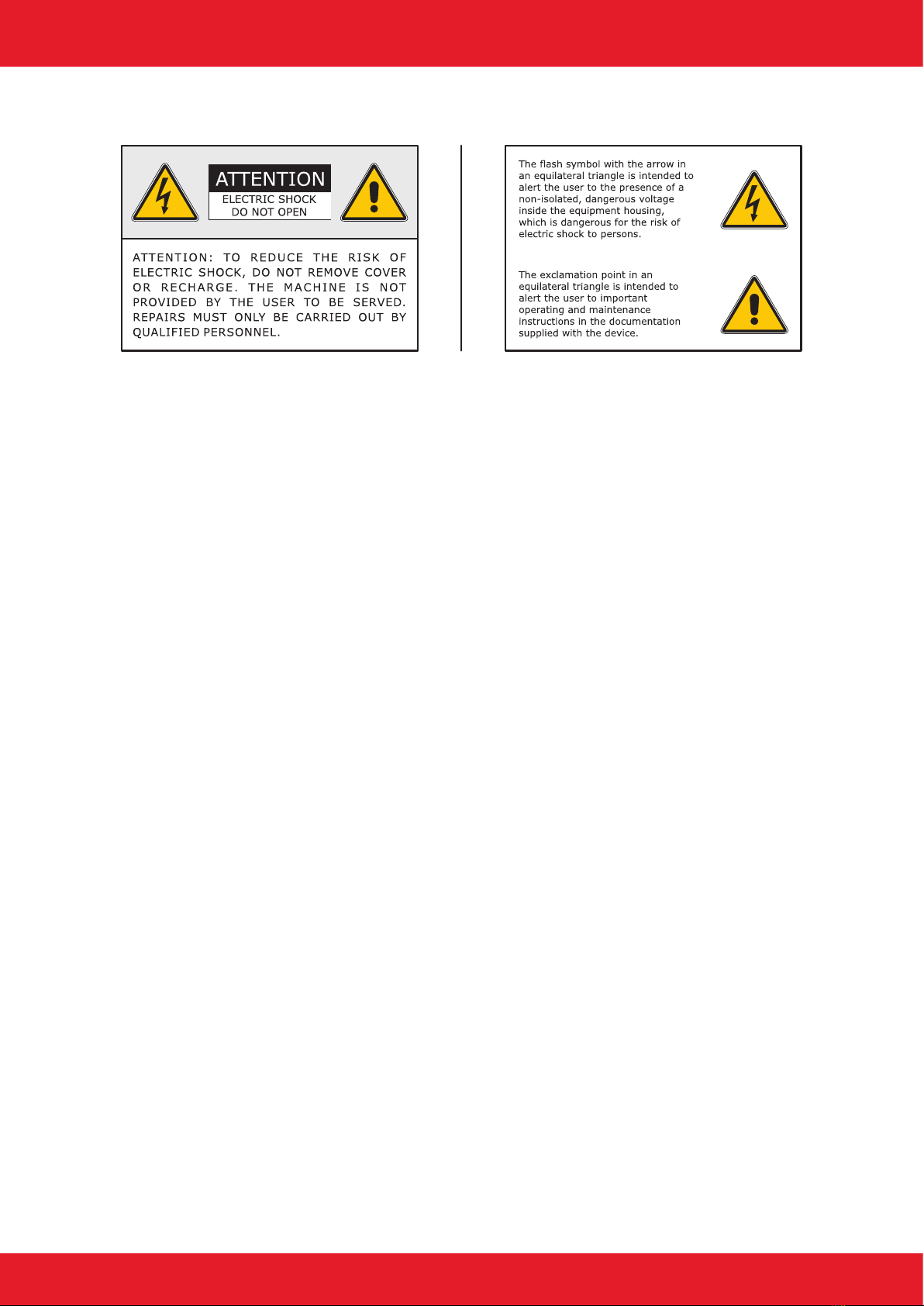
Safety Instructions Active Electronics
Read these instructions.
Observe all warning instructions.
Follow all operating instructions.
To prevent re hazard or risk of electric shock, do not use this device in the rain or in moist environments. Do
not operate the unit nearby the water.
Clean the unit only with a dry cloth.
Observe the instructions from the manufacturer for the mounting of the unit.
Do not mount the unit in the proximity of heat sources, such as heating units, herds or other heat radiation
devices.
Install the power cable at places where it cannot be damaged, especially at the sites of the socket, extension
cables and where it leaves the unit.
Never remove the safety device from the two terminal or grounding-type plug. A two-pin plug has two dierent
plug contact widths. An earth plug has two plug contacts and a third contact for earthing. The wider plug cont-
act or additional earth contact is for your safety. If the supplied plug size does not t in your socket box, please
consult an electrician for exchanging the socket box.
Only use additional devices/accessory parts, that meet the manufacturer‘s instructions.
Pull the power plug out in case of storm or when you do not use your device for a longer period.
All maintenance works must be performed by qualied service sta. Maintenance is required when the unit has
been damaged, objects or uids have leaked or fallen inside, when the unit was exposed to rain or humidity, or
in case of malfunctioning or when it has fallen on the oor.
Introduction

Page 5 of 15Manual VENIA-6sp DDA - 2021-12 EN
General Safety Instructions:
Loudspeakers produce a static magnetic eld even if they are not connected or are not in use. Therefore make
sure when erecting and transporting loudspeakers that they are nowhere near equipment and objects which
may be impaired or damaged by an external magnetic eld. Persons with cardiac pacemakers must maintain a
safe distance.
The minimum recommended safety clearance is 1 m.
Never stand in the immediate vicinity of loudspeakers driven at a high level. Professional loudspeaker systems
are capable of causing a sound pressure level detrimental to human health. Seemingly non-critical sound levels
(from approx. 90 dB SPL) can cause hearing damage if people are exposed to it over a long period.
All connected cables must be laid in such a way that they cannot be crushed by objects and that nobody can
step on them! Replace damaged cables immediately and do not use them!
Use only accessory parts specied by Voice-Acoustic or original accessory parts from Voice-Acoustic. Check all
cabinets and accessories regularly for wear and replace them if necessary.
Do not set up the loudspeakers in places where they are permanently exposed to moisture, dust, dirt or direct
sunlight.
Care
Wipe the surface of loudspeakers only with a damp cloth and pure water. In case of heavy pollution, repeat the
above procedure several times if necessary. Do not use any chemical additives or aggressive detergents, as
these may harm and damage the surfaces.
Transport and storage
When transporting and storing the unit, it is important to ensure that the surface and front grill of the loudspe-
aker are not damaged. Moisture can penetrate through exposed wood surfaces and cause the wood to swell.
A bent or broken front grill will no longer adequately protect the sensitive speaker membranes. In addition,
appreciable dust deposits may considerably impair the functionality of a loudspeaker membrane. For this rea-
son, the loudspeakers should be transported and stored in a safe, careful, dry and largely dust-free manner.
The following accessory parts for transport and storage are available from Voice-Acoustic:
■Carrying bag for 1 x VENIA-6 (Art.-Nr. 504602000)
■Heavy-duty ightcase for up to two 2 x VENIA-6 (Art.-Nr. 504603000)
Note: The original packaging is unsuitable as permanent storage and transport packaging!
Warranty
The warranty period is 24 months from date of delivery.
On our choice we will eliminate any lack of conformity with repair or with replacement of the faulty goods. The
place of performance for warranty services is Voice-Acoustic headquarters in Dörverden. In case of remedy of
defects, the buyer shall bear all costs resulting from transportation of the goods to Voice-Acoustic headquarters
in Dörverden.
The ordering party is not entitled to remedy the defect by itself or to organise a replacement and to charge
such activities to Voice-Acoustic. In case of self remedy by the ordering party the warranty given by Voice-
Acoustic becomes void.
Warranty doesn’t apply to parts of wear and tear, such as threaded points, such as threaded points, ying
tracks, tilting pole socket, rubber feet and the SpeakON®connectors.
Introduction

Page 6 of 15Manual VENIA-6sp DDA - 2021-12 EN
Introduction
Components
1. 20 x M10 mounting points with internal steel brackets
2. 15 and 12 mm multiplex cabinet, Surface with moisture resistant polyurea coating
3. 6 x M10 mounting point for U-bracket
4. Recessed grip on the underside
5. Dual-Tilt socket 0° and 5°
6. 4 x rubber feet on the underside
7. 1“ Neodym compression driver with 1,75“ voice coil
8. 6,5“ Neodym woofer with 1,8“ voice coil
9. Front grille 1 mm with 5 mm acoustic foam
10. Easyy ying track for vertical suspension
11. Safety point for safety rope with Single-Stud
12. M6 threaded points for mounting a wall or ceiling bracket
13. Control element* with type plate and serial number
14. SpeakON®connector
15. Amplier module with cooling ns and fan
16. Threaded points in the back wall for mounting bracket handle
17. M10 threaded point in the rear wall
18. powerCON TRUE1 connectors
*For equipment and functions see Voice-Acoustic-Control operating manual.
4
5
6
7
8
9
10
1
2
3
11
12
13
14
15
17
16
18
Page 7 of 15Manual VENIA-6sp DDA - 2021-12 EN
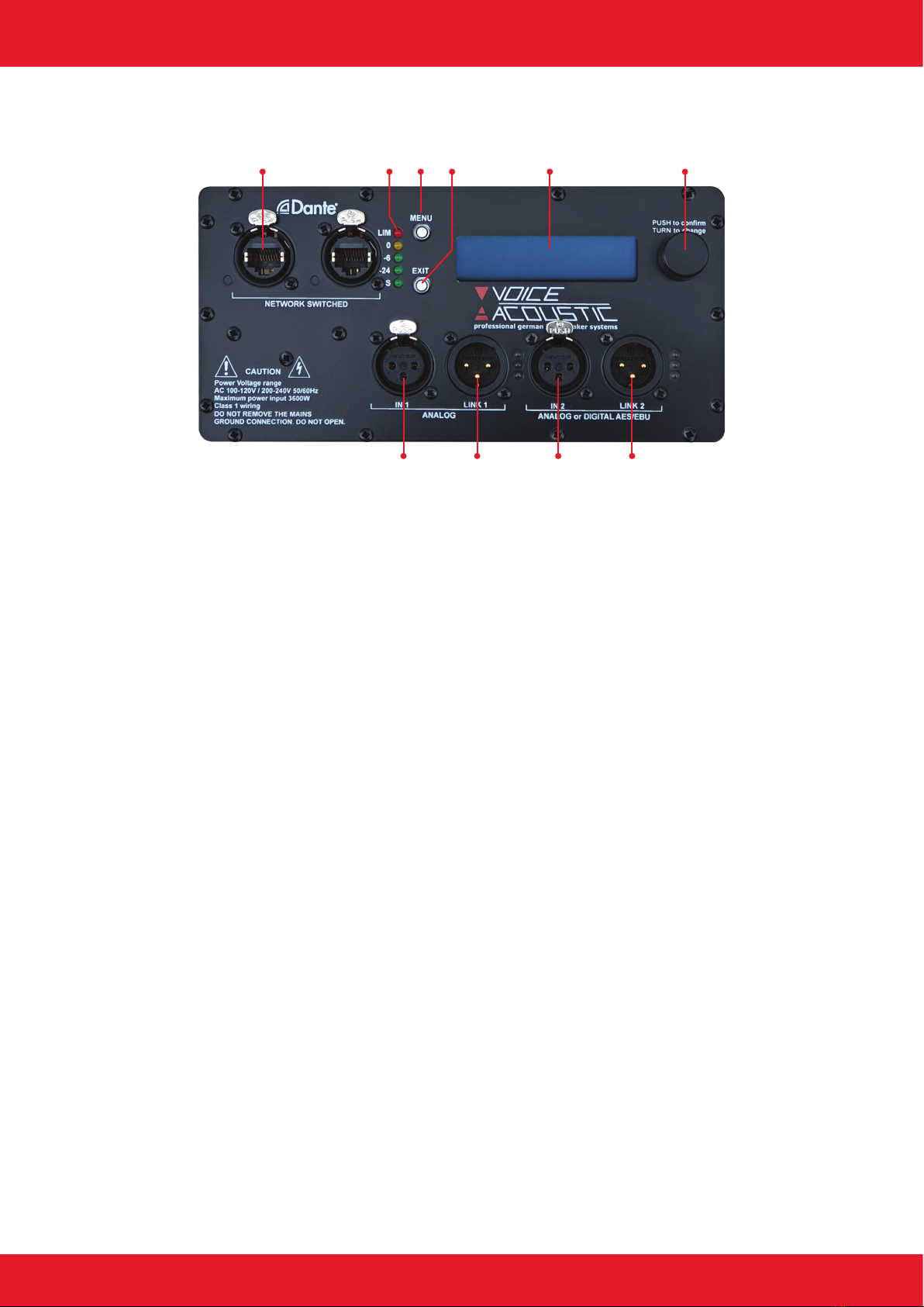
Connections Control element
1 32 4 5 6
7 8 9 10
01. Dante Network-Switch
Dante (Digital Audio Network Through Ethernet) for network connection.
02. Peak Level LEDs
Displays the current PEAK level in 5 levels: -18 dB, -12 dB, -6 dB (green), -3 dB (yellow), Limit (red).
03. Button top
To enter the system menu and browse between the conguration functions.
04. Button bottom
To leave the system menu or the conguration functions.
05. LCD Display
Background lit double-space 16-Segment LCD Display, for all important edition parameters.
06. Encoder wheel
You can change the parameter values with the encoder wheel. You can select dierent parameter values
by pressing and set them by turning.
07. Analog input
1 x Separate 3-pin connector for audio input. The input is a symmetric XLR-connector.
08. Analog output
1 x Separate 3-pin connector for audio output. The output is a symmetric XLR-connector.
09. Analog or Digital AES/EBU input
1 x Separate 3-pin connector for audio input.
10. Analog or Digital AES/EBU output
1 x Separate 3-pin connector for audio output.
Introduction
Page 8 of 15Manual VENIA-6sp DDA - 2021-12 EN
Introduction
Technical data
Components LF: 4 x 6,5“ Neodym woofer with 1,8“ voice coil
HF: 3 x 1“ Neodym compression driver with 1,75“ voice coil
Frequency response 48 Hz - 19 kHz (- 10 dB)
80 Hz - 19,5 kHz (+/- 3 dB)
Coverage range (h x v) 100° x 0°/ -20°
Powerhandling 800 W AES / 1.600 W program / 3.200 W peak at 8 Ω
Sound pressure 128 dB SPL AES / 131 dB SPL program / 134 dB SPL peak
Dimensions / Weight 1.050 (H) x 213 (W) x 390 (D) mm / 32,9 kg
Finish Polyurea coating in RAL 9005
Integrated 2-Way Amplier Modul
Power output CH1 2.400 W/4 Ω, 1.580 W/8 Ω, 800 W/16 Ω
Power output CH2 800 W/4 Ω, 450 W/8 Ω, 200 W/16 Ω
Amplier gain CH1 32 dB, CH2/3 26 dB
Signal-to-noise ratio >120 dB (20 - 20.000 Hz, 8 Ω)
Damping factor >1.000 (8 Ω, 1 kHz)
Distortion THD+N < 0,05 % (20 - 20.000 Hz, 8 Ω )
Integrated Loudspeaker Management System
Manual hand operation 2 button and 1 x digital encoder-wheel
Operable language Selectable between English, German, France, Spain
Software connection Bi-directional connection in real time via USB, Ethernet
Controllable units Up to 128 self-powered Speaker & HDSP-amplier in one network
DSP preset memory quantity 120 Presets
Processor 64 bit, 96 kHz sample rate
Dynamic range input 120 dB
Maximum input level + 23 dB
Latency 0,5 ms
Routing 2-input signals can mix together in one loudspeaker
EQ lter 10 parametric lter each In- and Output
X-Over Butterworth, Bessel, Linkwitz-Riley
Limiter In each Input and Output

Page 9 of 15Manual VENIA-6sp DDA - 2021-12 EN
Introduction
Setup
The VENIA-6sp DDA loudspeaker is designed for standing, vertical operation. A variety of accessories is availab-
le from Voice-Acoustic to securely attach the loudspeaker safely on tripods, distance rods or hanging it from on
trusses, ceilings and walls. Ensure that the loudspeakers are securely attached to prevent personal injury and
damage of property.
Connecting cables
When connecting the cables to the loudspeaker, ensure that the polarity (+/-) and pin assignment (1/2) is
correct. Incorrect connection results in a signicant change in the loudspeaker sound characteristics and may
damage the compression driver.
The two connection sockets on the back of the loudspeaker can be used to link multiple loudspeakers on a
single amplier. Note that parallel connection reduces the total impedance (Ω) seen by the amplier. The total
impedance of loudspeakers connected in parallel must not drop below the minimum operating impedance of the
amplier.
Voice-Acoustic recommends to use the available 4 x 4 mm² Speakon cables for mobile use.
We recommend wiring the basses with at least 4 mm² in installations. The cables of the tops in installations
must be suciently dimensioned according to impedance, power and cable length.
Simplied display without consideration of loudspeaker impedances
Operation
A VENIA-6sp DDA can feed a VENIA-6 via a 4 pin cable.
The woofers and compression drivers are designed in 8 Ω.
Make sure the appropriate preset has been selected before connecting the speaker to the system power amp or
self-powered subwoofer.
Using the wrong preset can damage parts of the loudspeaker.

Page 10 of 15Manual VENIA-6sp DDA - 2021-12 EN
Mounting X-Tension Kit
The X-Tension Kit can be mounted on any subwoofer or steel base
plate with M20 threaded mounting.
1. To connect the X-Tension Kit to the VENIA column line array,
mount the stacking adapter (A) to the bottom of the speaker.
2. Use the M10 countersunk screw (B) at the rear and two M6
countersunk screws (C) of the dual-tilt ange.
3. Place the column line array with the stacking adapter on the
X-Tension Kit and secure it with the two locking pins inside the
X-Tension Kit.
Note: Make sure that both locking pins are engaged to prevent
the column line array from tipping down.
Headstacking ying equipment mounting
The headstacking ying equipment allows the installation of two
VENIA column line arrays connected at the top using the EasyFly
mechanism, ring eyes and self-lock hooks.
1. Rotate a column line array 180°.
2. Mount the headstacking ying equipment to the bottom of
the rotated column line array using the four M10 countersunk
screws (D) on the sides.
3. Place the rotated column line array on top of the other column
line array so that they sit ush head to head.
4. Connect the column line arrays using the four headstacking
connectors (E). Again, use the M10 countersunk screws on the
sides of the column line arrays.
Note: Please note that the column line arrays only have rub-
ber feet on the underside. To avoid damaging the housing, you
should use underlays when mounting.
Working with VENIA-6sp DDA
A
B
D
E
C

Page 11 of 15Manual VENIA-6sp DDA - 2021-12 EN
Mounting the U-bracket
1. Remove the M10 countersunk screws on both sides of the co-
lumn line array.
2. Use the supplied M10 hexagon head screws (A) including pla-
stic washers to mount the U-bracket.
3. To protect the coatings, place the plastic washers between the
hex bolt, U-bracket and the column line array.
Mounting the C-bracket
1. On the top and bottom of the column line array, remove the
two M10 countersunk screws in the rear area.
2. Use the supplied M10 hexagon head screws (B) including pla-
stic washers to mount the C-bracket.
3. To protect the coatings, place the plastic washers between the
hex bolt, C-bracket and the column line array.
Mounting the tilting and swivelling wall brackets
1. When mounting the bracket to the wall, follow the manufactu-
rer‘s operating instructions.
2. Remove the swivel bracket on the wall bracket.
3. Use two M6 x 15 mm threaded screws and washers to x the
swivel bracket to the two M6 threaded points (C) on the rear of
the loudspeaker.
4. Hang the swivel bracket (with mounted speaker) into the bra-
cket attached to the wall.
5. Screw parts together using the lower carriage bolt, washer and
lock nut.
6. Adjust and x the tilt.
Working with VENIA-6sp DDA
A
B
C
Page 12 of 15Manual VENIA-6sp DDA - 2021-12 EN
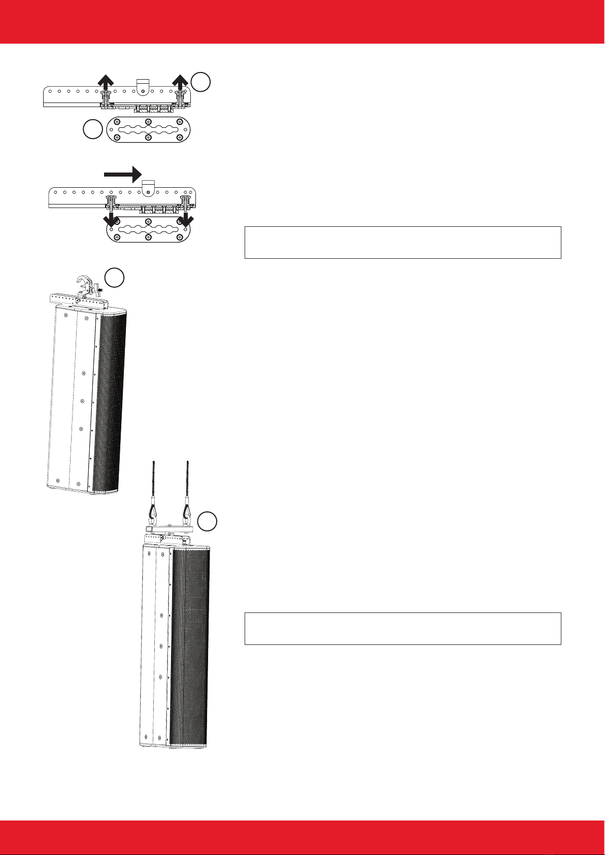
Easyy mechanics
Tool-less ight mechanism for clicking in and exact alignment of the
loudspeaker in the horizontal and vertical axis.
1. Pull the two locking bolts (A) upwards and let them engage by
turning them slightly.
2. Insert the Easyy mechanics into the ying track (B).
3. Slide the mechanics backwards as far as it will go.
4. Let the two locking bolts snap into the intended holes on the
ying track.
Note: Notice that the two locking pins (A) are engaged to pre-
vent the Easyy-Mechanics from slipping out.
Installations with Easyy mechanics
Installation with self-lock clamp (C) on trusses.
1. Mount the self-lock clamp to the Easyy mechanics using an
M10 threaded screw and lock nut.
2. Hang the clamp and holder into the mechanics using ball lock
bolts.
3. Hang the loudspeaker into the truss.
4. Adjust the inclination by xing the holder on the top hole rail
with the ball locking pin.
Installation with universal suspension arrangement for ight mecha-
nics (D) on high ceilings
1. Mount the universal suspension arrangement for ight mecha-
nics with an M10 threaded screw and lock nut to the mounting
of the Easyy mechanics.
2. Hang the suspension device and holder into the mechanics
using ball locking bolts.
3. Hang the loudspeaker into the installed chains.
4. Adjust the inclination by xing the holder on the top hole rail
with the ball locking pin.
Note: The inclination depends on the hole in which you x the
Easyy mount on the hole rail!
Working with VENIA-6sp DDA
C
D
A
B
Page 13 of 15Manual VENIA-6sp DDA - 2021-12 EN
Working with VENIA-6sp DDA
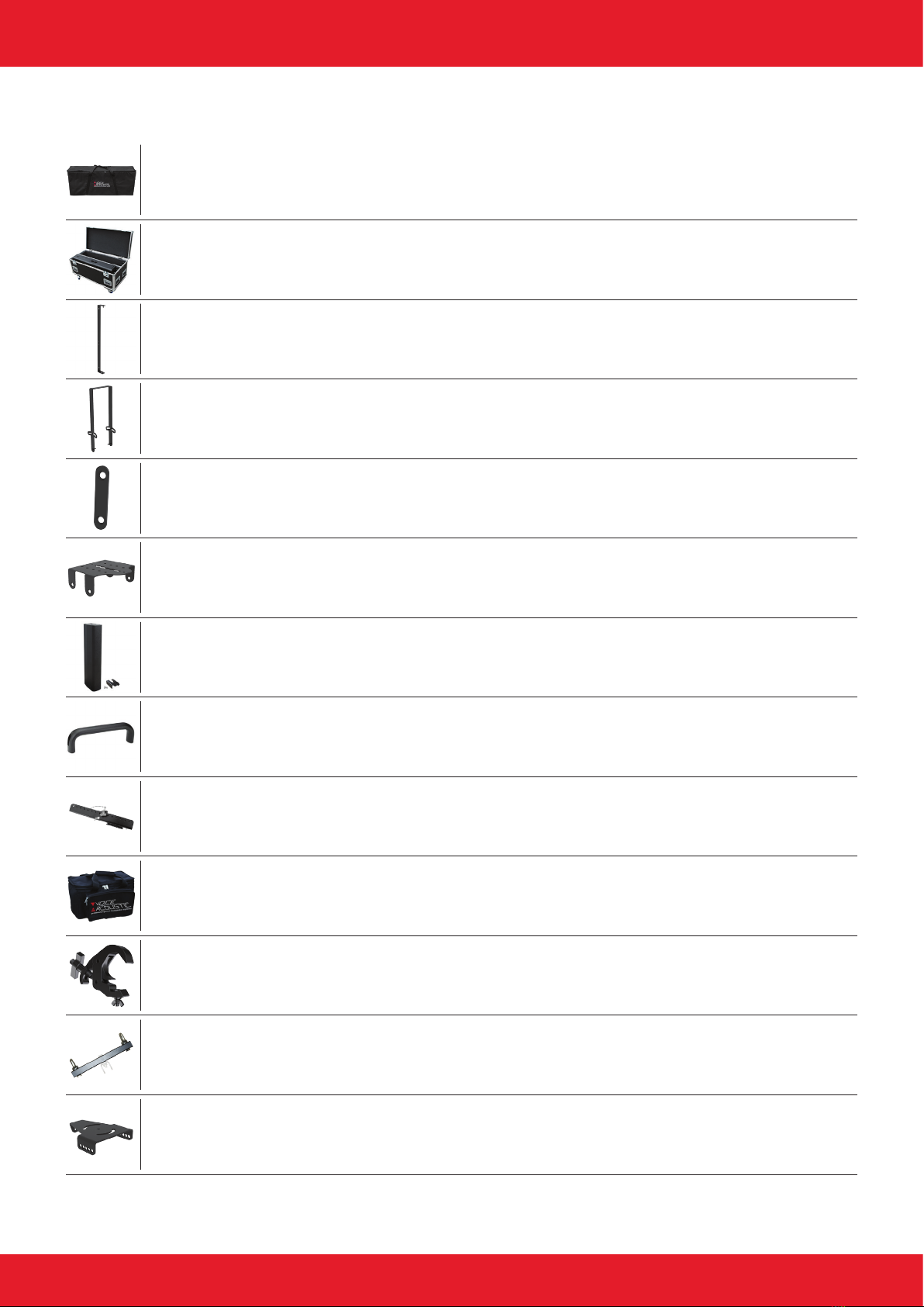
Overview Accessories
Universal suspension arrangement for ight mechanics (Art.-Nr. 409992001)
Self lock clamp for pipe 48-51mm, 30mm wide, max. 250 kg (Art.-Nr. 999950731)
Easyy mechanics (Art.-Nr. 409991001)
Carrying bag for up to two Easyy mechanisms with accessories (Art.-Nr. 409992000)
Multifunctional rotating ceiling bracket (Art.-Nr. 409998001)
Carrying bag for 1 x VENIA-6 (Art.-Nr. 504602000)
X-Tension Kit for VENIA-6 (Art.-Nr. 504607000)
Headstacking ying equipment for VENIA-6 (Art.-Nr. 404607001)
Headstacking connector for VENIA series (Art.-Nr. 409999001)
Aluminum bracket handle (Art.-Nr. 999995651)
Heavy-duty ightcase for up to two VENIA-6 (Art.-Nr. 504603000)
C-bracket for VENIA-6 (Art.-Nr. 404603000)
U-bracket for VENIA-6 (Art.-Nr. 404601000)

Page 14 of 15Manual VENIA-6sp DDA - 2021-12 EN
Wall console for ight hardware (Art.-Nr. 409994901)
Wall holder with tilt and swivel orientation: 145° horizontal, 30° vertical (Art.-Nr. 999924173)
Wall bracket, max. 50 kg, slewable and 22° tiltable (Art.-Nr. 999924120)
Wall- and truss holder, max. 50 kg, slewable (Art.-Nr. 999924150)
Safety 6/1000 mm (Art.-Nr. 999963100)
M10 x 40 mm eyebolt (Art.-Nr. 999917370)
Single stud tting (Art.-Nr. 999957450)
Wall bracket, slewable and 30° tiltable (Art.-Nr. 999924481)
Wall bracket, slewable and 30° tiltable, white (Art.-Nr. 999224481)
Wall mount with extension (Art.-Nr. 409994031)
Wall mount with extension, white (Art.-Nr. 409994032)
Working with VENIA-6sp DDA

Page 15 of 15Manual VENIA-6sp DDA - 2021-12 EN
Manufacturer‘s declaration
Imprint
© SRV Licht- & Tonanlagen, all rights reserved.
All specications in this manual are based on information available
at the time of publishing for the features and safety guidelines of
the described products. Technical specications, measurements,
weights and properties are not guaranteed.
The manufacturer reserves the right to make technical modications
according to legal regulations stipulating the continual improvement
of product features. For the safe operation of the unit, this manual
and all other required information must be available to all users at
the time of assembly and disassembly of the unit, and during opera-
tion. Assemble or operate the unit only after reading and understan-
ding this manual, and keeping it at hand at all times at the site.
We are happy to receive your suggestions and proposals for the
enhancement of this manual.
Please send us your ideas to the following address:
SRV Licht- & Tonanlagen - Voice-Acoustic Headquarters
Brocksfeld 3
D-27313 Dörverden
Tel.: + 49 (0) 4234 942 777
E-Mail: [email protected]
Table of contents
Other Voice-Acoustic Speakers manuals

Voice-Acoustic
Voice-Acoustic LA-Stick 4x4 User manual

Voice-Acoustic
Voice-Acoustic Modular-15sp User manual

Voice-Acoustic
Voice-Acoustic Alea-4 User manual

Voice-Acoustic
Voice-Acoustic Modular-15 User manual

Voice-Acoustic
Voice-Acoustic VENIA-8sp DDA User manual

Voice-Acoustic
Voice-Acoustic Score-8 User manual

Voice-Acoustic
Voice-Acoustic Modular-10 User manual

Voice-Acoustic
Voice-Acoustic Score-5 User manual


