Void Cyclone 8 User manual

voidacoustics.com
Cyclone 8
Sculpted sound, compact styling
USER GUIDE V2.0

©2022 Void Acoustics Research Ltd.
This user guide is subject to change without notice.
For the latest online version, visit: www.voidacoustics.com
Void Acoustics and the Void logo are registered trademarks of Void Acoustics
Research Ltd. in the United Kingdom, USA and other countries; all other Void
trademarks are the property of Void Acoustics Research Ltd.

UG10582-2.0 - Cyclone 8 User Guide V2.0 Page 3
Contents
1 Safety and Regulations 4
1.1 Important Safety Instructions 4
1.2 Limitations 4
1.3 EC Declaration of Conformity 4
1.4 UKCA Conformity 4
1.5 Warranty Statement 4
1.6 WEEE Directive 4
2 Unpacking and Checking 5
3About 6
3.1 Welcome 6
3.2 Cyclone 8 Overview 6
3.3 Key Features 6
3.4 Cyclone 8 Specifications 7
3.5 Cyclone 8 Dimensions 7
4 Cable and Wiring 8
4.1 Electrical Safety 8
4.2 Cable Considerations for Fixed Installations 8
4.3 Phoenix Connector 8
4.4 Cyclone Glanded Connector Wiring 9
4.5 Cyclone 8 Wiring Diagram 11
4.6 Bias D1/Q1/Q2 Phoenix Wiring 11
4.7 Bias Q3/Q5 speakON™ Wiring 12
5 Mounting 13
5.1 Installation Safety 13
5.2 Wall Mounting 14
5.3 Ceiling Mounting 16
6 Service 18
6.1 Return Authorisation 18
6.2 Shipping and Packing Considerations 18
7 Appendix 19

Page 4UG10582-2.0 - Cyclone 8 User Guide V2.0
1.1 Important safety instructions
The lightning flash with an arrowhead symbol
within an equilateral triangle is intended to alert the
user to the presence of uninsulated “dangerous
voltage” within the product’s enclosure that may
be of sucient magnitude to constitute a risk of
electric shock to persons.
The exclamation point within an equilateral triangle
is intended to alert the user of the presence of
important operating and maintenance (servicing)
instructions in the literature accompanying the
appliance.
Safety instructions - read this first
1. Read these instructions.
2. Keep these instructions.
3. Heed all warnings.
4. Follow all instructions.
5. Do not use this apparatus near water.
6. Clean only with a dry cloth.
7. Do not block any ventilation openings. Install in accordance with
the manufacturer’s instructions.
8. Do not install near any heat source such as radiators, heat
registers, stoves, or other such apparatus that produce heat.
9. Do not defeat the safety purpose of the grounding-type plug. A
grounding type plug has two blades and a third grounding prong.
The third prong is provided for your safety. If the provided plug
does not fit into your outlet, consult an electrician for replacement
of the obsolete outlet.
10. Protect power cords from being walked on or pinched
particularly at plugs, convenience receptacles, and the point where
they exit the apparatus.
11. Only use attachments and accessories specified by Void
Acoustics.
12. Only use with the cart, stand, tripod, bracket, or table specified
by the manufacturer, or sold with the apparatus. When a cart is
used, use caution when moving the cart/apparatus combination to
avoid injury from tip-over.
13. Unplug the apparatus during lightning storms or when unused
for long periods of time.
14. Refer all servicing to qualified service personnel. Servicing
is required when the apparatus has been damaged in any way,
such as when the power-supply cord or plug is damaged, liquid
has been spilled or objects have fallen into the apparatus, the
apparatus has been exposed to rain or moisture, does not operate
normally, or has been dropped.
15. Since the mains power supply cord attachment plug is used to
disconnect the device, the plug should always be easily accessible.
16. Void loudspeakers can produce sound levels capable of
causing permanent hearing damage from prolonged exposure.
The higher the sound level, the less exposure needed to cause
such damage. Avoid prolonged exposure to the high sound levels
from the loudspeaker.
1.2 Limitations
This guide is provided to help familiarise the user with the
loudspeaker system and its accessories. It is not intended to
provide comprehensive electrical, fire, mechanical and noise
training and is not a substitute for industry-approved training. Nor
does this guide absolve the user of their obligation to comply
with all relevant safety legislation and codes of practice. While
every care has been taken in creating this guide, safety is user-
dependent and Void Acoustics Research Ltd cannot guarantee
complete safety whenever the system is rigged and operated.
1.3 EC declaration of conformity
For EC Declaration of Conformity please go to:
www.voidacoustics.com/eu-declaration-loudspeakers
1.4 UKCA marking
For details of the UKCA marking go to:
www.voidacoustics.com/uk-declaration-loudspeakers
1.5 Warranty statement
For warranty statement go to:
https://voidacoustics.com/terms-conditions/
1.6 WEEE directive
If the time arises to throw away your product, please recycle all
the components possible.
This symbol indicates that when the end-user
wishes to discard this product, it must be sent
to separate collection facilities for recovery
and recycling. By separating this product from
other household-type waste, the volume of
waste sent to incinerators or land-fills will be
reduced and natural resources will thus be
conserved.
The Waste Electrical and Electronic Equipment Directive (WEEE
Directive) aims to minimise the impact of electrical and electronic
goods on the environment. Void Acoustics Research Ltd complies
with the Directive 2002/96/EC and 2003/108/EC of the European
Parliament on waste electrical finance the cost of treatment and
recovery of electronic equipment (WEEE) in order to reduce the
amount of WEEE that is being disposed of in land-fill sites. All of
our products are marked with the WEEE symbol; this indicates that
this product must NOT be disposed of with other waste. Instead
it is the user’s responsibility to dispose of their waste electrical
and electronic equipment by handing it over to an approved
reprocessor, or by returning it to Void Acoustics Research Ltd for
reprocessing. For more information about where you can send
your waste equipment for recycling, please contact Void Acoustics
Research Ltd or one of your local distributors.
1 Safety and Regulations

Page 5UG10582-2.0 - Cyclone 8 User Guide V2.0
2 Unpacking and Checking
All Void Acoustics products are carefully manufactured and thoroughly tested before being
despatched. Your dealer will ensure that your Void products are in pristine condition before
being forwarded to you but mistakes and accidents can happen.
Before signing for your delivery:
• Inspect your shipment for any signs of contamination, abuse or transit damage as soon
as you receive it
• Check your Void Acoustics delivery fully against your order
• If your shipment is incomplete or any of its contents are found to be damaged; inform
the shipping company and inform your dealer.
When you are removing your Cyclone 8 loudspeaker from its original packaging:
• Cyclone 8 loudspeakers come double boxed are stapled shut; take care when unboxing
and removing the staples to avoid injury or damage to the loudspeaker
• If you need to place the loudspeaker on a flat surface ensure you use a lint free product to
protect the finish
• When you have removed the Cyclone 8 loudspeaker from the packaging inspect it to en-
sure there is no damage and keep all original packaging in case it needs to be returned for
any reason.
See section 1.5 for warranty conditions and see section 6 if your product needs service.

Page 6UG10582-2.0 - Cyclone 8 User Guide V2.0
3 About
3.1 Welcome
Many thanks for purchasing this Void Acoustics Cyclone Series loudspeaker. We truly
appreciate your support. At Void, we design, manufacture and distribute advanced professional
audio systems for the installed and live sound market sectors. Like all Void products, our highly
skilled and experienced engineers have successfully combined pioneering technologies with
groundbreaking design aesthetics, to bring you superior sound quality and visual innovation. In
buying this product, you are now part of the Void family and we hope using it brings you years
of satisfaction. This guide will help you both use this product safely and ensure it performs to
its full capability.
3.2 Cyclone 8 overview
As the ideal mid-point solution between the Cyclone 55 and the Cyclone 10 models, the
Cyclone 8 oers an installation-friendly package with an IP-55 rating that can be used
both indoors and outdoors. Whether it’s a stand-alone application for beach bars, lounges,
restaurants, cruise ships and hotels, or providing area fill when used with a larger main club
system, high-quality sound is a given. State-of the-art porting minimises turbulent noise and
maximises LF performance. The low frequency transducer and 1” coaxially mounted high
frequency compression driver provide increased eciency for its compact, stylish form.
Flexible mounting solutions enable quick, secure installation with a wide range of adjustment.
3.3 Key features
• Passive 8” two-way surface mount loudspeaker
• Compact fibreglass enclosure
• Non-resonant structure
• Marine-grade stainless steel fittings
• UV resilient paint
• Weather-protected with an IP-55 rating (BS EN 60529:1992 +A2:2013)
Page 7UG10582-2.0 - Cyclone 8 User Guide V2.0
3 About
3.4 Cyclone 8 specifications
Frequency response 70 Hz - 20 kHz ±3 dB
Eciency194 dB 1W/1m
Nominal impedance 8 Ω
Power handling2200 W AES
Maximum output3118 dB cont, 121 dB peak
Driver configuration 1 x 8” LF, 1 x 1” HF coaxial
Dispersion 90°H x 90°V
Connectors Phoenix
Height 281 mm (11”)
Width 450 mm (17.7”)
Depth 317 mm (12.5”)
Weight 14 kg (31 lbs)
Enclosure Fibreglass
IP Rating IP-55 (BS EN 60529:1992 +A2:2013)
Rigging Optional T80XL wall bracket
Finish Smooth cellulose
1Measured in half space 2AES2 - 1984 compliant 3Calculated
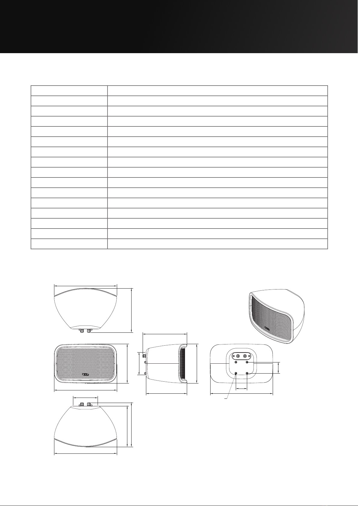
3.5 Cyclone 8 dimensions
281 (11”)
450 (17.7”)
317 (12.5”)
293 (11.5”)
177 (7”)
450 (17.7”)
317 (12.5”)
450 (17.7”)
281 (11”)
293 (11.5”)
317 (12.5”)
162 (6.4”)
450 (17.7”)
80 (3”)
80 (3”)
4xM8 Fixtures
Figure 3.1: Dimensions

Page 8UG10582-2.0 - Cyclone 8 User Guide V2.0
4 Cable and Wiring
4.1 Electrical safety
To avoid electrical hazards please note the following:
• Do not access the inside of any electrical equipment. Refer servicing to
Void-approved service agents.
4.2 Cable considerations for fixed installations
We recommend specifying installation-grade Low Smoke Zero Halogen (LSZH) cables for
permanent installations. The cables should use Oxygen Free Copper (OFC) of grade C11000
or above. Cables for permanent installations should be compliant with the following standards:
• IEC 60332.1 Fire retardancy of a single cable
• IEC 60332.3C Fire retardancy of bunched cables
• IEC 60754.1 Amount of Halogen Gas Emissions
• IEC 60754.2 Degree of acidity of released gases
• IEC 61034.2 Measurement of smoke density.
We suggest using the following maximum copper cable lengths to keep level losses below 0.6 dB.
Metric mm2Imperial AWG 16 Ωload 8 Ωload 4 Ωload 2 Ωload
2.50 mm213 AWG 72 m 36 m 18 m 9 m
4.00 mm211 AWG 120 m 60 m 30 m 15 m
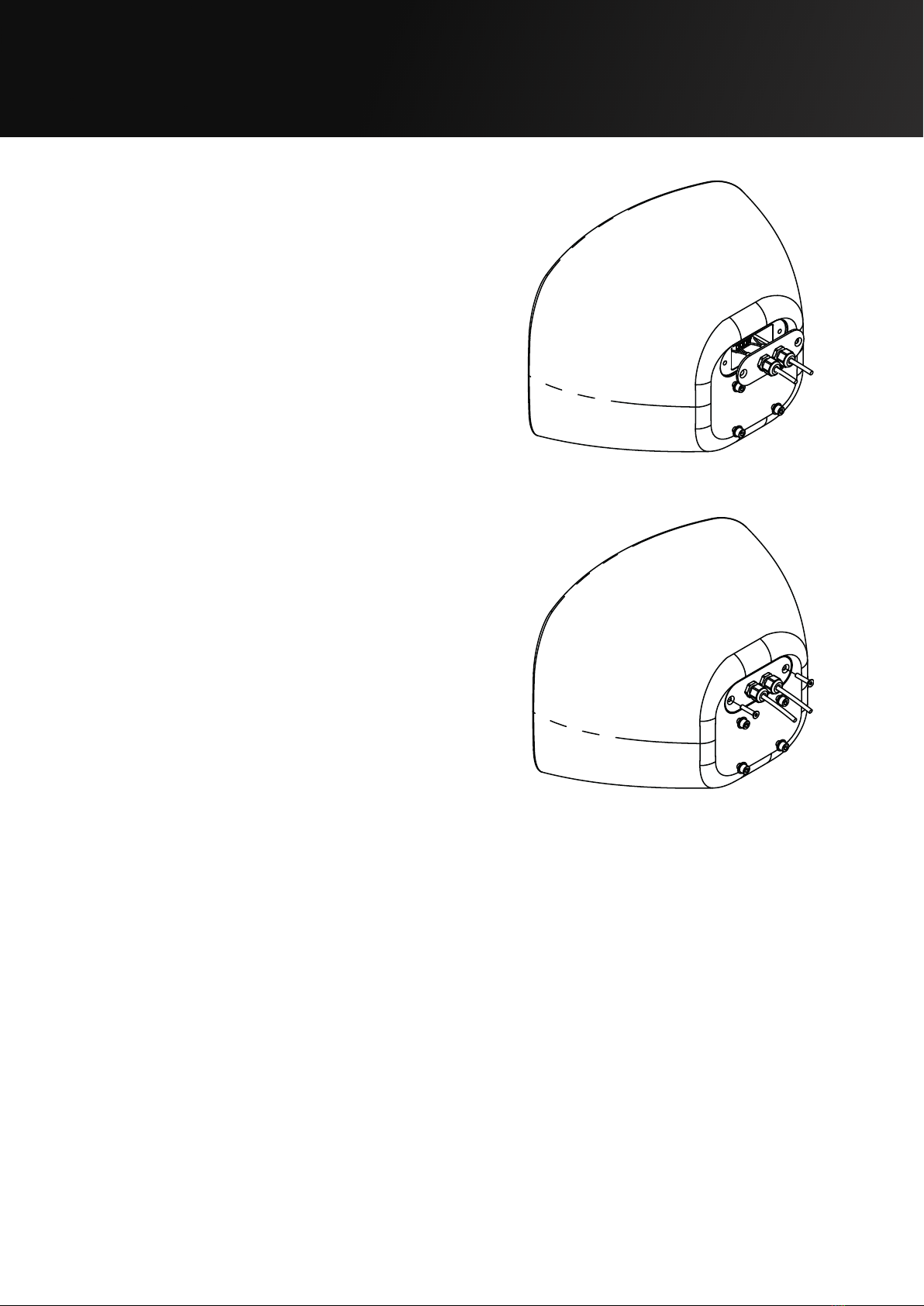
4.3 Phoenix connector
Figure 4.1 shows the rear panel of a Cyclone Series loudspeaker with the polarity of the
Phoenix connector labelled. When viewed from the rear the connectors are negative,
positive, negative, positive, from left to right.
+ +- -
Figure 4.1: Phoenix connector diagram

Page 9UG10582-2.0 - Cyclone 8 User Guide V2.0
4 Cable and Wiring
4.4 Cyclone glanded connector wiring
• Remove both M6 bolts from the rear of the
connector plate
• Undo the glanded connectors from the rear of
the connector plate.
• Insert the cable through the glanded
connectors and tighten.
Figure 4.2: Connector plate removal
Figure 4.3: Glanded connector removal
Figure 4.4: Cable connection
Page 10UG10582-2.0 - Cyclone 8 User Guide V2.0
• Attach the cable to the phoenix connector.
• Position the connector plate and insert the
two M6 bolts.
Figure 4.5: Phoenix attachment
Figure 4.6: Connector plate connection
4 Cable and Wiring
Table of contents
Other Void Speakers manuals

Void
Void Air Vantage User manual

Void
Void AXSYS 15 User manual

Void
Void Venu 6 User manual

Void
Void Cirrus 4.1 User manual

Void
Void Nexus Series User manual

Void
Void Venu 210i V2 User manual

Void
Void Mycro 8 User manual

Void
Void AIRTEN User manual

Void
Void Airten V3 User manual

Void
Void Cyclone Series User manual

Void
Void Cyclone 10 User manual

Void
Void Nexus Q User manual

Void
Void Sub Vantage User manual

Void
Void Air Motion User manual

Void
Void ArcM-12 User manual

Void
Void Cyclone 55 User manual

Void
Void Venu 210i User manual

Void
Void Cyclone 4 User manual

Void
Void Venu V2 Series User manual

Void
Void IMPULSE t SERIES User manual


