VOITAS WALLBOX 5 M User manual
USER MANUAL
VOITAS WALLBOX 5 m / 8 M
v.
User Manual
TABLE OF CONTENT S fety Instructions 1
Introduction 3
Dr wings nd dimensions 4
Inst ll tion 5
Inst ll tion Guide 6
First use nd set-up 8
Ch rging process 9
RFID | RCD 10
LED Effects 11
D t sheet 12
VOITAS SMART METER 13
Setup & Inst ll tion guide 14
Instructions nd Connections
di gr ms 15
D t sheet 17
Safety Instructions
CAUTIO
Please kee a co y of this manual
throughout the life of the roduct. This
document contains the information
necessary for the safe installation and use
of the VOITAS WALLBOX electric vehicle
charger. Before using it for the rst time,
read the entire contents of the manual,
es ecially the safety recautions.
VOITAS WALLBO
VOITAS Innovations GmbH is not res onsible for the
material damage caused by failure to follow installation and
o erating instructions, use of unauthorized s are arts or
accessories, or em loyment of unqualied ersonnel. Use of
the VOITAS WALLBOX is ermitted only if the installation
has been carried out ro erly by a qualied electrician.
Safety-threatening malfunctions must be corrected only by
qualied ersonnel. You can contact the VOITAS Innovations
technical su ort through our website
We recommend installing the VOITAS WALLBOX indoors
or under the roof), without direct sunlight to revent
overheating. The VOITAS WALLBOX reduces charging
ower when the tem erature is too high
Do not install the VOITAS WALLBOX in an area rone to
ooding or direct water s ray. Do not clean the VOITAS
WALLBOX with a direct stream of water
Before charging, always check the VOITAS WALLBOX for
visible damage
The charger must be grounded (PE wire connected and
ro erly routed in the electrical system)
The minimum unwinding of the cable is marked with a
yellow label, and the maximum unwinding value with a
red label
The water rotection hood of the ty e 2 lug must be
ut on, otherwise water will accumulate in the ca
CAUTION
Always unwind the cable at least up to the yellow label
when charging to avoid overheating of the device
1
Safety Instructions
2
VOITAS SMART METE
The device must be connected to a three-phase network
according to the current norms and standards. The method
of connection is specied in this manual
CAUTION!
Installati n, c nnecti n, and adjustment activities sh uld
be carried ut by qualied electricians wh are familiar with
the instructi ns and functi ns f the device. Disassembling
the h using will v id the warranty and p ses a danger f
electric sh ck
Before starting the installation, ensure there is no voltage on
the connection wires. Installation of the device is not
recommended in the following cases: missing components,
damage or deformation of the device, or defective electrical
installation. In case of malfunction, contact the
manufacturer.
Introduction
Thank you for choosing our product
The VOITAS WALLBOX is part of an extendable EV
charging system that allows for safe, convenient,
and efcient charging of EVs according to IEC
61851 1, mode 3
The system consists of
The VOITAS WALLBOX an EV charger that can
be purchased with RFID tokens, RCD protection
and two cable lengths 8 and 5 meters. The
VOITAS WALLBOX can work independently or
be paired with the VOITAS SMART METER
The VOITAS APP from which you will be able to
manage settings, users, and see statistics and
reports on charging history. Make sure that your
device and the VOITAS WALLBOX are
connected to the internet
The VOITAS SMART METER a two way energy
meter, installed in electrical systems where
there is a photovoltaic installation (or another
form of energy production). Its main task is to
monitor the electrical system for excess energy.
With this data, the VOITAS WALLBOX can
adjust the charging power to use only the
energy generated from the photovoltaic
installation. Without the VOITAS SMART METER,
the VOITAS WALLBOX works like a regular EV
charger
An RFID module allows user authentication,
preventing unwanted use of the VOITAS
WALLBOX where the charger is installed in a
public area
3
The RCD module is an additional safety measure.
Designed and manufactured by VOITAS Innovations,
it provides built in differential current monitoring
and electric shock protection
For more information on our charging system or other
products, please visit: www.voitas innovations.com
VOITAS WALLBOX nameplat
S/N indicates the serial number of the VOITAS
WALLBOX. It is located at the service ap of the device
NOTE
The serial number (S/N) is required to register your
device in the VOITAS Wallbox App
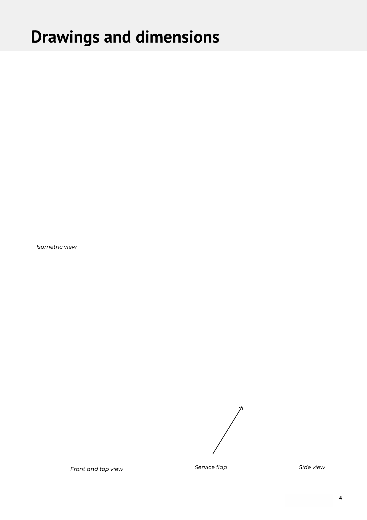
Drawings and dimensions
Isometric view
Side viewService ap
Front and top view
4
Installation
NOTE
For detailed instructions on how to install
and connect the VOITAS WALLBOX, see
nstallation Guide section.
To ensure the safe use of the VOITAS WALLBOX, the
user must install the device according to the
instructions in this manual
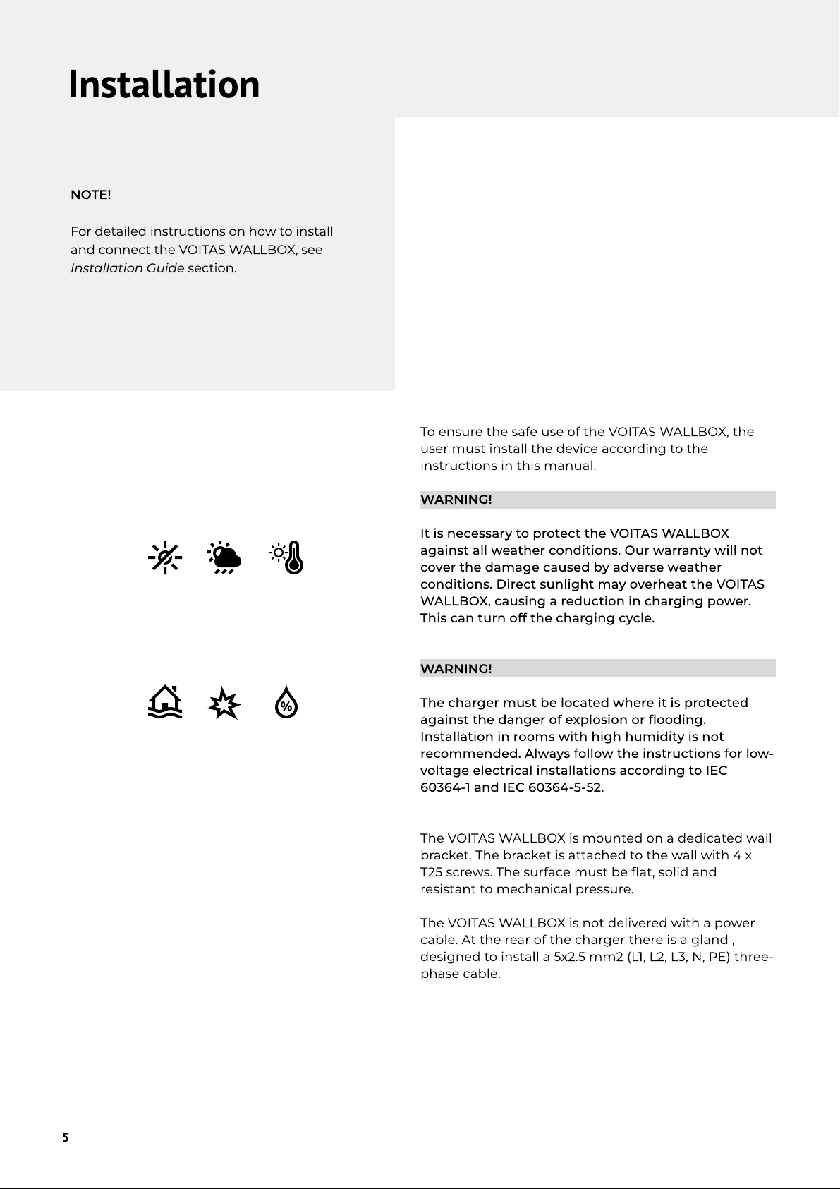
WARNING
It is necessary to protect the VOITAS WALLBOX
against all weather conditions. Our warranty will not
cover the damage caused by adverse weather
conditions. Direct sunlight may overheat the VOITAS
WALLBOX, causing a reduction in charging power.
This can turn off the charging cycle
WARNING
The charger must be located where it is protected
against the danger of explosion or ooding.
Installation in rooms with high humidity is not
recommended. Always follow the instructions for low-
voltage electrical installations according to IEC
60364-1 and IEC 60364-5-52
The VOITAS WALLBOX is mounted on a dedicated wall
bracket. The bracket is attached to the wall with 4 x
T25 screws. The surface must be at, solid and
resistant to mechanical pressure
The VOITAS WALLBOX is not delivered with a power
cable. At the rear of the charger there is a gland ,
designed to install a 5x2.5 mm2 (L1, L2, L3, N, PE) three-
phase cable
5
Installation Guide
TOOLS NEEDED
Dri
6 mm dri bit
T25 screwdriver
eve
penci
wire cutting p iers
wire stripper
T20 screwdrive
MOUNTING THE BRACKET
1. P ace the bracket on the at surface where you want
to mount it and a ign it vertica y with a dri ing
temp ate and eve
2. Mark the four mounting openings of the bracket on
the surface
3. Dri the openings to a depth of 45 mm
4. Hammer in the wa p ugs
5. P ace the bracket on the wa and drive the screws
into the wa studs
6. Make sure the screws are tightened rm y
7. Now you can hang the VOITAS WALLBOX
CONNECTING THE VOITAS WALLBOX TO THE
ELECTRICAL SYSTE
NOTE
For convenience when connecting to the e ectrica
system, remove the VOITAS WALLBOX from the
bracket
1. Prepare a three-phase exib e e ectrica cab e (5x2.5
mm2), so the device can be pivoted. The maximum
diameter of the power cab e compatib e with the
cab e g and on the VOITAS WALLBOX is 18 mm
2. Cut it to the ength required to reach the point in
your e ectrica system where you have decided to
insta the VOITAS WALLBOX
WARNING
Make sure that the electrical installation can support
a continuous supply of 16A per phase (Among other
things, the overcurrent protection in this segment is
at least 16A, and the wires have the appropriate cross-
section)
6

Installation Guide
3. Strip 11 mm of each wire
4. Unscrew the M4x12 screw and remove the
inspection ap from the bottom of the VOITAS
WALLBOX
5. Pull the cable through the cable gland and screw it
tightly
6. Lift the terminals on the unconnected side of the
WAGO connectors according to the diagram
7. Slide the wires into the corresponding cavities (blue
wire - neutral, yellow-green wire - protective PE wire,
brown - phase one, black - phase two, gray - phase
three)
8. Check the correctness in the WAGO connectors
WARNING
Do not to ch the side with the wires connected
WARNING
Do not install the VOITAS WALLBOX in areas where
the PE cable is missing! The charger will not work
properly
7

First Use & Set-up
FIRST USE AND SET-U
When the VOITAS WALLBOX is installed and
connected according to the instructions, you can
proceed with the device conguration. Make sure the
VOITAS WALLBOX is within the range of your Wi-Fi
network or connected to your network via an Ethernet
port
CAUTION
The Ethernet port is located near the power
connection of the VOITA WALLBOX
CAUTION
If the device does not respond, make sure the power
switch is turned to the ‘ON’ position
VOITAS WALLBOX will turn on its access point itself.
Launch the VOITAS Wallbox App on your phone and
register the account
Connect to your access point with your phone the
same way, as you were connecting to the network. The
app will guide you through the process of assigning
the VOITAS WALLBOX to your account and connecting
it to your home Wi-Fi network
Once you have assigned the VOITAS WALLBOX to your
account, you can manage it from the app level
NOTE
At the rst start it is recommended that the VOITAS
WALLBOX is connected to the internet to get the
latest updates. Please wait around 60 minutes to let
the device update and restart itself. The Wallbox
searches for Over-the-air Updates every hour
CAUTION
For instructions on how to connect and
use the VOITA MART METER, see
Chapter 14 and 15
8

Charging Process
CHARGING PROCES
After the rst use, the charging process goes as
follows
1. Check the LED panel. f it glows white, the
VO TAS WALLBOX is ready for charging. f you
purchased VO TAS RF D tokens you can use the
functionality of the RF D reader mounted in the
Wallbox. RF D conguration is available in the
VO TAS APP
2. (RF D VERS ON ONLY) place the RF D fob on
the front panel, between the LED strips and the
cable opening. f the RF D fob is recognized, it will
be signaled by the LEDs of the device
3. Open the cover of the vehicle's charging socket
and unwind the cable. The cable reel integrated
into the VO TAS WALLBOX has a locking
mechanism - it locks itself with each rotation and
locks the cable. The VO TAS WALLBOX is
equipped with a mechanism preventing the
automatic cable winding, locking the wire in the
desired position. To unlock the mechanism
slightly pull the wire for it to automatically rewind
4. Connect the cable to your vehicle. Charging will
start automatically, and LED bars will indicate
that the charging process is in progress
5. f you want to stop charging, disconnect the
cable from the vehicle. The VO TAS WALLBOX will
recognize this and signal a return to standby
6. Disconnect the cable and pull it to unlock the
mechanism and safely rewind the cable into the
VO TAS WALLBOX
WARNING
The VO TAS WALLBOX 8 requires at least 5 meters of a
cable to be unrolled, and the VO TAS WALLBOX 5
requires at least 2 meters to be unrolled
The cables have a spot marked with a yellow label,
which you will see when unwinding the cable. f this
label is not visible, do not connect the cable
WARNING
Do not let go of the cable until it is rolled up again
CHARGING PARAMETER
The user can control many parameters of the charging
process using the VO TAS WALLBOX app in the
Settings section
You can change the charging mode from “Grid” (no
change in charging power) to “Solar Panels” (charging
using excess energy from the photovoltaic
installation)
The maximum charging current, and the number of
phases, can be changed manually using the slider in
the application under “Settings”. First set the
WALLBOX to "off" with the slider and then switch the
phases to "three phases". Then set the slider back to
"on"
By default, the VO TAS WALLBOX charges with a
maximum current of 16A on 3 phases
9

RFID | RCD
RFI
RFID identication is an optiona feature of the
VOITAS WALLBOX, which can be added in the
conguration step when ordering the VOITAS
WALLBOX. P ease note that the RFID function of
the VOITAS WALLBOX on y works with VOITAS
RFID tokens.
It a ows to secure the unit and verify the user.
RFID tokens are assigned to individua user
accounts in the VOITAS WALLBOX App in the
conguration section in oca WIFI-mod
(see detai ed instructions in the App).
When the RFID function is enab ed, an additiona
verication step is triggered. To start charging, the
user must scan the registered RFID token. This
operation needs to be repeated for every charging
cyc e
NOTE
In this setting, without RFID authentication, the
VOITAS WALLBOX wi not respond to being
connected to the car
The RFID reader is ocated between the LED strips
and under the charging cab e retraction opening
RCD - DIFFERENTIAL CURRENT MONITORING
AND ELECTRIC SHOCK PROTECTION
The VOITAS WALLBOX is equipped with an RCD
modu e that monitors the eve of residua current
and the continuity of the PE wire. In case of
damage to any of the charging e ements (both the
VOITAS WALLBOX, or e ectric vehic e being
charged) the RCD modu e ensures that the user is
additiona y protected against e ectric shock
If the RCD modu e detects a fau t, it wi cut off the
power of the VOITAS WALLBOX. To reset the RCD
modu e, press the button: “RESET RCD” in the App or
restart the device, by opening the service ap and turn
the power off and on. In the LED-overview you nd out
how to recognize a RCD modu e fau t
WARNING!
Please note that electrical safety regulations vary
based on location. In some regions, the charging
station must be protected by an additional, externally
mounted RCD device
Technical parameters of the RCD included in the
VOITAS WALLBOX
Type A differentia current monitoring device.
Min. differentia current: 14.1 mA RMS.
Vo tage Rating: 230V/400V 50 Hz
Contro ed switching device: the VOITAS WALLBOX
main re ays
10

LED Effects
DISPLAY MARKING
The VOITAS WALLBOX h s three LED b rs on the
front p nel to indic te different st tes nd
modes
11

Datasheet
Power / Charging
Mechanical data
Additional info
12
Nominal load current / voltage / v.
frequency 16A/230V/50Hz
Charging current range 6 – 16 A
Charging power 11 kW (3 - phase); 3,7 kW (1 - phase)
Charging mode IEC 61851-1, Mode 3.
Connection to the vehicle Type 2 plug
Compatible electrical installation
topologies TN-S, TN-C-S
Shock protection Residual current device, PE conductor
continuity monitoring
Dimensions 395x350x182 [mm]
Weight 5,3 kg for 8 m version
4,5 kg for 5 m version
Ingress protection IP54
Working ambient temperature range From -25 °C to 40 °C
Mounting Dedicated mounting bracket, mounted
on a indoor wall or under a roof.
Cable 5 m and 8 m versions, integrated cable
retractor
Communication W
L
AN,
L
AN, M
O
D
BU
S TCP
RFID veri
cation
O
ptional
Additional accessoires (optional) V
O
ITAS Smart Meter, RFID card reader,
RFID pendants
App control
Y
es
Compliance with norms, directives and
certi
cates
RoHS, 2014/32/E
U
&
2014/53/E
U
directives;
IEC 61851-1, Mode 3

VOITAS Smart Meter
The VOITAS SMART METER makes the VOITAS
WALLBO system unique. The main advantage of the
VOITAS WALLBO is that in addition to being a
charger for electric vehicles, it has the ability to adjust
automatically based on feedback from the electrical
system. This is used for surplus charging
To take advantage of this feature of the VOITAS
WALLBO , the user needs the VOITAS SMART METER.
This device acts as a two-way energy meter that
monitors the electrical system for surplus energy.
Surplus energy occurs in electrical installations with
any source of power generation such as a photovoltaic
installation.
The VOITAS SMART METER is designed to be installed
with main switchboard of a power grid
The VOITAS SMART METER measures active power
with current transformers and voltage measurement
of individual phases of the power grid. The VOITAS
WALLBO connects to the VOITAS SMART METER via
Wi-Fi, retrieves power values from it, and based on
these values, determines the amount of surplus power
returned to the grid. This power under load
management can be directed entirely to charging the
car. Using load management this power can be
directed entirely to charge the car
VOITAS SMART METER nameplat
S/N indicates the serial number of the VOITAS Smart
Meter. It is located on one side of the VOITAS Smart
Meter
13
Set-up & Installation Guide
1. Make sure your electrical panel has free space
on a DIN rail with a width of 4 modules
2. Make sure you have access to a three-phase
supply that connects directly to the grid (three-
transformer conguration), the wires coming out
of the PV inverter and the grid wires that power
all electrical equipment (see the next section for
diagrams)
3. If the actions from point 2 cannot be
completed, purchase a small portable
switchboard with at least 4 DIN-rail modules, and
install it where it allows you to reach the phase
wires from the power grid, and connect it
according to the diagram corresponding to your
electrical installation
4. Connect the power supply to the VOITAS
SMART METER according to the connection
diagram appropriate to your installation (see the
next section for diagrams).
WARNING
Pay special attention to the order of phases and
the correct connection of the neutral wire
ENTER INTERNET ONNE TION
ONFIGURATION MODE
1. When the power is connected, the PWR LED
will indicate that the device is on, and the Wi-Fi
LED, located on the left side will blink 5 times per
second
2. Hold down the “Reset” and “BTN” button for
about 5 seconds. The L1, L2 and L3 LEDs will
indicate entry into conguration mode
3. Wait until the Wi-Fi LED blinks more slowly about
once a second
4. Go to the device conguration in the App
5. At Network Name type in “SmartMeter” (without
quotation
6. At Network Password type in “SMARTMETER”
(without quotation) and select “Connect
7. Congure the SmartMeter as outlined in the
Quickstart Guide and connect it to the local Wi-Fi
access point. If necessary, check the values of the
individual phases of current transformers 1-6
NOTE
Make sure that the VOITAS SMART METER is within
range of your Wi-Fi network
WARNING
Installation must be performed only by a
qualied electrician
14
Instructions and Connection Diagram
NOTE
The VOITAS SMART METER can be connected to
the electrical system in 3 ways, using three or six
current transformers
CT1 and CT4 transform rs m asur th curr nt
owing in phas L1
CT2 and CT5 transform rs m asur th curr nt
owing in phas L2
CT3 and CT6 transform rs m asur th curr nt
owing in phas L3
CT1, CT2, CT3 transform rs ar mark d as prob 1
in th App
CT4, CT5, CT6 transform rs ar mark d as prob 2
in th App
Th transform rs ar dir ctional and must b
plugg d in prop rly
THE VOITAS SMART METER CONNECTION DIAGRAMS
TO THE GRI
Variant
Wh n you hav acc ss to th wir s of th PV inv rt r,
and th wir s coming out of th pow r grid
(Prob 1 GRID, Prob 2 Solar)
Variant
Conn cting th PV installation with 3 curr nt
transform rs
(Prob 1 GRID, Prob 2 Non )
15

Instructions and Connection Diagram
Variant
If you do not have access to the wires coming out of
the power grid
(Probe 1 Solar, Probe 2 House)
Variant
If you do not have access to the wires connecting the
PV inverter to the home grid
(Probe 1 GRID, Probe 2 House)
16
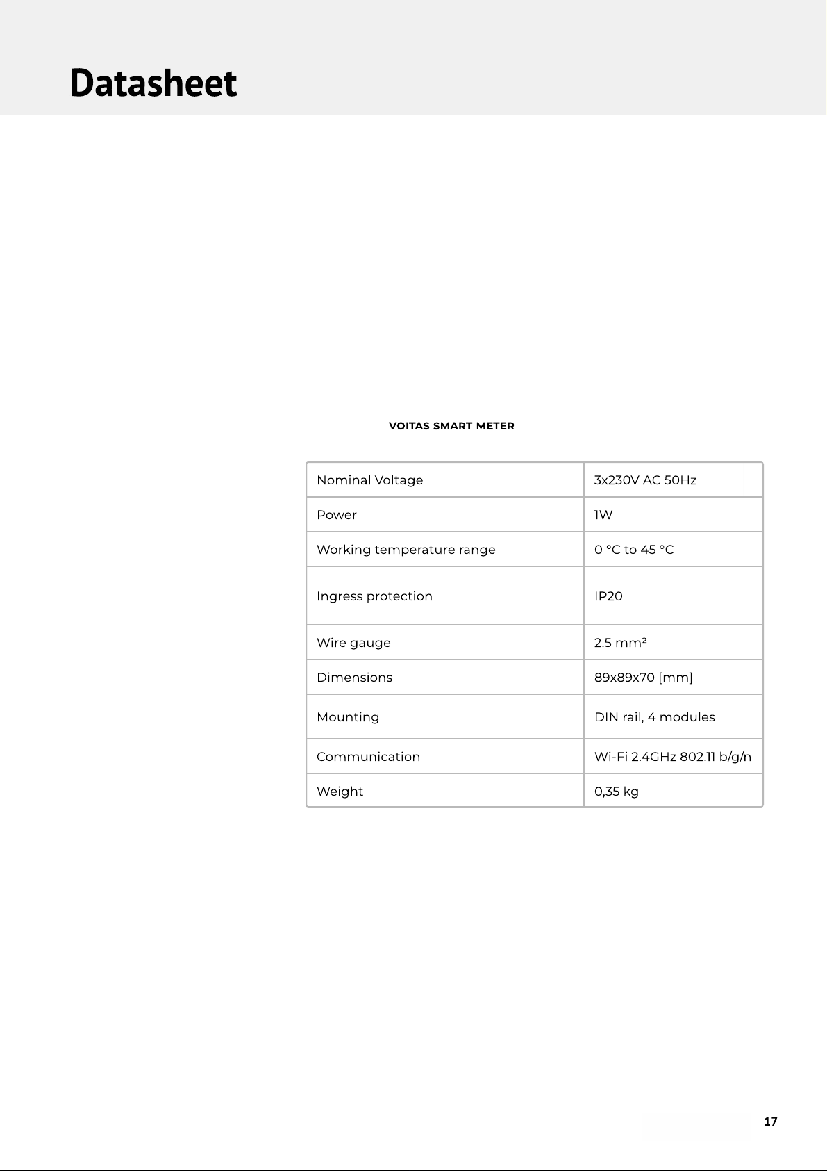
Datasheet
Nominal Voltage 3x230V AC 50Hz
Power 1W
Working temperature range 0 °C to 45 °C
Ingress protection IP20
Wire gauge 2.5 mm2
Dimensions 89x89x70 [mm]
Mounting DIN rail, 4 modules
Communication Wi-Fi 2.4GHz 802.11 b/g/n
Weight 0,35 kg
VOITAS Smart Meter
17
voitas-innovations.com
USER MANUAL (EN)
This manual suits for next models
1
Table of contents
Other VOITAS Batteries Charger manuals


Popular Batteries Charger manuals by other brands

efacec
efacec EFAPOWER EV-QC24S Installation and user manual

ACDelco
ACDelco I-7002 owner's manual

Belkin
Belkin BU3DC001-12V user manual

Webasto
Webasto Unite Operating and installation instructions

Intermec
Intermec AC13 supplementary guide

Intelligent Charging
Intelligent Charging TS25 MKII Operator's manual


