efacec EFAPOWER EV-QC24S User manual
EFAPOWER
EV QC24S
QUICK CHARGING STATION
Installation and User Manual
E F A P O W E R EV- Q C 2 4 S - I N S T A L L A T I O N A N D U S E R M A N U A L
ii
Copyright and trademarks
©2015 EFACEC. All rights reserved. This material is protected by the copyright laws of Portugal and other
countries. It may not be modified, reproduced or distributed without the prior, express written consent of
EFACEC. All other products or services mentioned are the trademarks, service marks, registered trademarks or
registered service marks of their respective owners.
Symbols Index
The following symbols are used in this manual to prevent accidents, which may occur as a result of incorrect
use of the charger.
Note
Read the notes carefully to ensure safe and proper use
Warning or safety observation
Read the instructions carefully to ensure safe and proper use
Risk of electric shock
Read the instructions carefully to ensure safe and proper use
Rua Eng.º Frederico Ulrich - Apartado 3078
4471-907 MOREIRA MAIA - PORTUGAL
Tel: (+351) 229403241 - Fax: (+351) 229403209
apvsa@efacec.com
www.electricmobility.efacec.com
2725 Northwoods Parkway, Ste. B
Norcross, Georgia 30071 USA
Tel: (1) 470 395-3648 -
Fax: (1) 770 446 8920
support.eem.usa@efacec.com
www.electricmobility.efacec.com

E F A P O W E R EV- Q C 2 4 S - I N S T A L L A T I O N A N D U S E R M A N U A L
iii
TABLE OF CONTENTS
1GENERAL PRODUCT DESCRIPTION............................................................................... 2
2GENERAL CHARACTERISTICS ....................................................................................... 3
2.1 TECHNICAL CHARACTERISTICS .......................................................................................................... 3
2.2 STANDARDS.................................................................................................................................. 4
3PRODUCT PARTS PRESENTATION ................................................................................ 5
4IMPORTANT SAFETY INSTRUCTIONS ........................................................................... 6
5INSTALLATION ............................................................................................................ 7
5.1 ENVIRONMENTAL REQUIREMENTS .................................................................................................... 7
5.1.1 Local Conditions ................................................................................................................................................... 7
5.1.2 Site Verification and Inspection............................................................................................................................ 8
5.2 SITE PREPARATION......................................................................................................................... 9
5.2.1 Upstream Wiring Information .............................................................................................................................. 9
5.2.2 Surface Preparation............................................................................................................................................ 11
5.2.3 Resources for Installation ................................................................................................................................... 11
5.2.4 Site Verification and Inspection.......................................................................................................................... 11
5.3 HANDLING AND PLACING .............................................................................................................. 12
5.3.1 Packaging........................................................................................................................................................... 12
5.3.2 Visual Inspection................................................................................................................................................. 12
5.3.3 Handling ............................................................................................................................................................. 12
5.3.4 Assembly/ Placing Instructions........................................................................................................................... 12
6START-UP ..................................................................................................................16
6.1 VERIFICATION AND INSPECTION...................................................................................................... 16
6.2 SWITCH ON................................................................................................................................ 16
7USER MANUAL ..........................................................................................................19
7.1 OUTPUT CONNECTOR ................................................................................................................... 19
7.1.1 CCS Connector .................................................................................................................................................... 19
7.2 OPERATING INSTRUCTIONS ............................................................................................................ 20
7.2.1 Operation sequences for EFAPOWER EV-QC24S without display ....................................................................... 21
7.2.2 Operating sequences for EFAPOWER EV-QC24S with display............................................................................. 22
8MAINTENANCE MANUAL ...........................................................................................24
8.1 PREVENTIVE MAINTENANCE .......................................................................................................... 24
8.2 TROUBLESHOOTING ..................................................................................................................... 25

E F A P O W E R EV- Q C 2 4 S - I N S T A L L A T I O N A N D U S E R M A N U A L
1 | 28
The information presented in this guide is subject to change without prior notice.
The technical specifications indicated here do not constitute a contractual obligation.
No part of this document may be photocopied, reproduced or translated to other languages without the written
consent from EFACEC.
In case of any doubt regarding a subject described in this manual, please contact us at:
Rua Eng.º Frederico Ulrich - Apartado 3078
4471-907 MOREIRA MAIA - PORTUGAL
Tel: (+351) 229403241 - Fax: (+351) 229403209
apvsa@efacec.com
www.electricmobility.efacec.com
2725 Northwoods Parkway, Ste. B
Norcross, Georgia 30071 USA
Tel: (1) 470 395-3648 -
Fax: (1) 770 446 8920
support.e[email protected]om
www.electricmobility.efacec.com

E F A P O W E R EV- Q C 2 4 S - I N S T A L L A T I O N A N D U S E R M A N U A L
2 | 28
1GENERAL PRODUCT DESCRIPTION
EFAPOWER EV-QC24S charging station is able to charge all electric vehicles compliant with Combined Charging
System (CCS) standard.
Depending on the battery capacity, EFAPOWER EV-QC24S can charge
properly equipped electric vehicles from 0% to 80% in roughly 60
minutes.
The charging session stop automatically based on signals from the EV,
or it can be manually stopped by the user.
EFAPOWER EV-QC24S is user friendly and safe. After user
identification, it only requires coupling the charger’s output plug in the
EV. The charge session will then start automatically after all safety
checks have been accomplished.
EFAPOWER EV-QC24S has a means of measuring the output energy,
which can be used for information and monitoring purposes. It uses
remote IP communication via GPRS, ADSL, WIFI or any other internet
access method to communicate business management data and
technical data.
The Quick Charger’s power electronics unique design results in top
tier specifications for conductive DC fast charging, such as high power
output with an industry best power factor, THD and efficiency.
EFAPOWER EV-QC24S has a switching technology with high reliability and high efficiency.
The Quick Charger is highly recommended for EV fleet bases, service stations, EV service workshops and public
EV infrastructure for fast charging.
EFAPOWER EV-QC24S codification and parts are presented in Chapter 3.
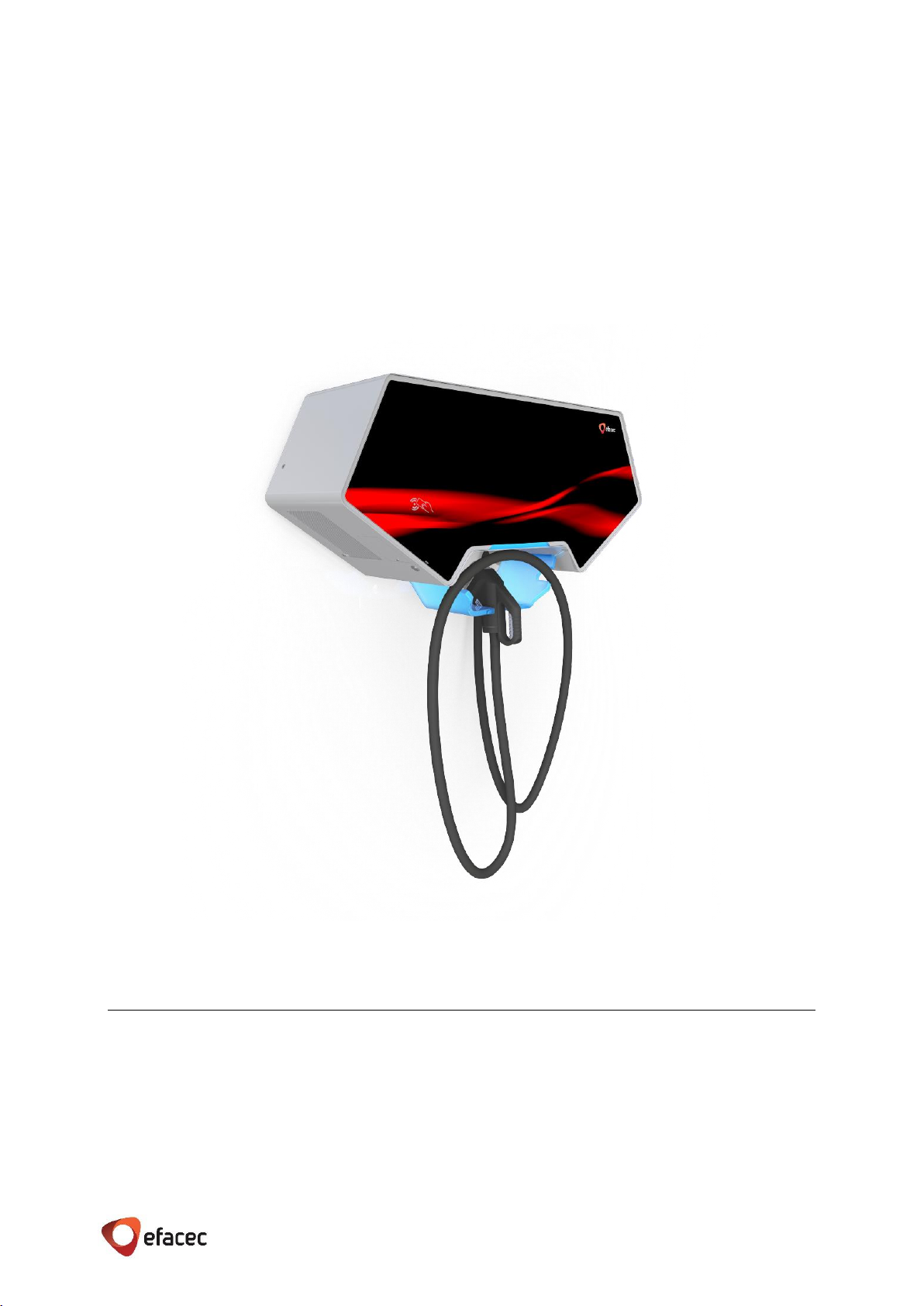
Figure 1 - EFAPOWER EV-QC24S

E F A P O W E R EV- Q C 2 4 S - I N S T A L L A T I O N A N D U S E R M A N U A L
3 | 28
2GENERAL CHARACTERISTICS
2.1 TECHNICAL CHARACTERISTICS
EFAPOWER EV-QC24S technical characteristics are indicated in the Table 1.
This unit is intended to have one DC output connection (CCS).
Table 1 –EFAPOWER EV-QC24S Technical Characteristics
Specifications are subject to change, without prior notice.
Technical Data
CE
ETL
Nominal Input
Three
Phases
Phases/Lines
3 phases + neutral + PE
3 phases + PE
Voltage
(400 ± 10%) V a.c.
(208 ± 10%) V a.c.
Current
37 A
71 A
Single
Phase
Phases/Lines
NA
1 phase 2 wire + PE
Voltage
(240 ± 10%) V a.c.
Current
106 A
Power
25.5kVA
Frequency
(50 ± 10%) Hz
(60 ± 10%) Hz
Efficiency
> 94%
Power Factor
0.99 @ full load; 0.98 @ half load
THD Input Current
Less than 5% @ full load; Less than 10% @ half load
DC Output:
CCS
Voltage
(260 to 425) V d.c.
Current
60 A d.c. (@ 400V d.c.)
Nominal Power
24kW ( adjustable up to this )
Communications with EV
PLC
Plug
CCS –Type 2
SAE –Type 1
Insulation
Input / Output / Ground
2800 V a.c.
2800 V a.c.
Control Circuit / Ground
500 Vac
Cabinet
Dimensions(WxDxH)
1005 x 365 x 567 mm
39.4 x 14.2 x 19.7 inches
Weight
60 kg
132 lbs.
Protection Degree
IP54, IK10
NEMA 3R
HMI and Command
Unit
Contactless card specification
Mifare Classic 1K&4K, DesFire EV1
(Others under request)
Local interface
RFID; Button; LED’s
TFT color display 4,3’ (optional)
Communication
Protocol (others under request)
Web Services over IP; Router 3G (GSM or CDMA)
OCPP; Efacec;
Emergency STOP
Yes
Environment
Conditions
Temperature
-25ᵒ to +40ᵒC
-13ᵒ to +104ᵒF
Humidity
5% to 90%
Place of installation
Indoor / Outdoor
Altitude
Up to 1000m
Up to 3280 feet
Sound Noise
<55 dB in all directions

E F A P O W E R EV- Q C 2 4 S - I N S T A L L A T I O N A N D U S E R M A N U A L
4 | 28
2.2 STANDARDS
The EFAPOWER EV-QC24S Quick Charging Station complies with the following standards:
Table 2 –EFAPOWER EV-QC24S Applicable Standards
1
2006/95/CE: Low Voltage Directive
2
2004/108/CE: EMC directive
3
EN/IEC 61851-1: Electric vehicle conductive charging system. Part 1: General Requirements
4
IEC 62196: Plugs, socket-outlets, vehicle connectors and vehicle inlets - Conductive charging of electric vehicles
5
UL 2231-1: Personnel Protection Systems for Electric Vehicle (EV) Supply Circuits: General Requirements
6
UL 2231-2: Personnel Protection Systems for Electric Vehicle (EV) Supply Circuits: Particular Requirements for
Protection devices for Use in Charging Systems
7
UL 2202: Electric Vehicle (EV) Charging System Equipment
8
SAEJ1772: SAE Surface Vehicle Recommended Practice J1772, SAE Electric Vehicle Conductive Charge Coupler
9
ADA: American with Disabilities Act
10
EN/IEC 61851-23: Electric vehicle conductive charging system - Part 23: DC electric vehicle charging station
11
EN/IEC 61851-24: Electric vehicle conductive charging system - Part 24: Digital communication between a d.c.
EV charging station and an electric vehicle for control of d.c. charging
12
EN/IEC 61000-6-2: Electromagnetic compatibility (EMC). Part 6-2: Generic standards –Immunity for industrial
environments
13
EN/IEC 61000-6-4: Electromagnetic compatibility (EMC). Part 6-4: Generic standards –Emission standard for
industrial environments
Technical Data
CE
ETL
Applicable
Standards
Universal:
2006/95/CE1
2004/108/CE2
EN/IEC 61851-13
IEC 621964
UL 2231-15
UL 2231-26
UL 22027
SAE J17728
ADA9
DC Charging System:
EN/IEC 61851-2310
EN/IEC 61851-2411
EN/IEC 61000-6-212
EN/IEC 61000-6-413
---

E F A P O W E R EV- Q C 2 4 S - I N S T A L L A T I O N A N D U S E R M A N U A L
5 | 28
3PRODUCT PARTS PRESENTATION
The mechanical structure is composed of a standalone wall box unit. Its model codification is presented below.
EFAPOWER EV-QC24S and its unit interfaces (HMI and output connection) are represented in the next figure.
Figure 3 - EFAPOWER EV-QC24S Parts
G–GSM
C–CDMA
X–Without Screen
C–Color Screen
EV-QC24S YY GCXB DCC C
CE –European markets
UL –USA & Canada markets
Figure 2 - EFAPOWER EV-QC24S Codes
STOP Button /
Emergency STOP Button
RFID Reader
LED signalling
charging status
Output plug
connection
TFT color 4,3’
(opcional)
Handling Instructions

E F A P O W E R EV- Q C 2 4 S - I N S T A L L A T I O N A N D U S E R M A N U A L
6 | 28
4IMPORTANT SAFETY INSTRUCTIONS
SAVE THESE INSTRUCTIONS
This manual contains important instructions that must be followed during installation of the EFAPOWER EV-
QC24S Quick Charging Station.
Grounding instructions
The EFAPOWER EV-QC24S Quick Charging Station must be connected to a grounded, metal, permanent wiring
system; or an equipment-grounding conductor is to be run with circuit conductors and connected to the
equipment grounding terminal or lead on the Electric Vehicle Supply Equipment (EVSE). Connections to the EVSE
shall comply with all local codes and ordinances.
Safety and compliance
This document provides instructions to install the EFAPOWER EV-QC24S Quick Charging Station and should not
be used for any other product. Before installing the EFAPOWER EV-QC24S Quick Charging Station, you should
review this manual carefully and consult with a licensed contractor, licensed electrician and trained installation
expert to ensure compliance with local building practices, climate conditions, safety standards, and state and
local codes. The EFAPOWER EV-QC24S Quick Charging Station should be installed only by a licensed contractor
and a licensed electrician and in accordance with all local and national codes and standards. The EFAPOWER EV-
QC24S Quick Charging Station should be inspected by a qualified installer prior to the initial use. Under no
circumstances will compliance with the information in this manual relieve the user of his/her responsibility to
comply with all applicable codes or safety standards. This document describes the most commonly-used
installation and mounting scenarios. If situations arise in which it is not possible to perform an installation
following the procedures provided in this document, contact EFACEC. EFACEC is not responsible for any damages
that may occur resulting from custom installations that are not described in this document.
No accuracy guarantee
Reasonable effort was made to ensure that the specifications and other information in this manual are accurate
and complete at the time of its publication. However, the specifications and other information in this manual are
subject to change at any time without prior notice.
Warranty information and disclaimer
Your use of, or modification to, the EFAPOWER EV-QC24S Quick Charging Station in a manner in which the
EFAPOWER EV-QC24S Quick Charging Station is not intended to be used or modified will void the limited
warranty. Other than any such limited warranty, the EFACEC products are provided “AS IS,” and EFACEC and its
distributors expressly disclaim all implied warranties, including any warranty of design, merchantability, fitness
for a particular purposes and non-infringement, to the maximum extent permitted by law.
Limitation of liability
IN NO EVENT SHALL EFACEC OR ITS AUTHORIZED DISTRIBUTORS BE LIABLE FOR ANY INDIRECT, INCIDENTAL,
SPECIAL, PUNITIVE, OR CONSEQUENTIAL DAMAGES, INCLUDING WITHOUT LIMITATION, LOST PROFITS, LOST
DATA, LOSS OF USE, COST OF COVER, OR LOSS OR DAMAGE TO THE EFAPOWER EV-QC24S STATION, ARISING
OUT OF OR RELATING TO THE USE OR INABILITY TO USE THIS MANUAL, EVEN IF EFACEC OR ITS AUTHORIZED
DISTRIBUTORS HAVE BEEN ADVISED OF THE POSSIBILITY OF SUCH DAMAGES.
E F A P O W E R EV- Q C 2 4 S - I N S T A L L A T I O N A N D U S E R M A N U A L
7 | 28
5INSTALLATION
All instructions for installing the EFAPOWER EV-QC24S are described in this chapter.
5.1 ENVIRONMENTAL REQUIREMENTS
EFAPOWER EV-QC24S reliability is dependent upon compliance of environmental specifications. The design of
the environmental control system for your EFAPOWER EV-QC24S, in case of extreme environmental conditions,
must ensure that the Unit can operate reliably while remaining within the range of its operating specifications.
5.1.1 LOCAL CONDITIONS
The installation of EFAPOWER EV-QC24S shall not be made closer than 6,1m (20 feet) of an outdoor
motor fuel dispensing device.
EFAPOWER EV-QC24S is in an IP54, IK10 (NEMA 3R) enclosure. This Unit is intended to work below 40ᵒC (104ᵒF)
ambient temperature.
Clearance around the unit
The air must circulate freely throughout the ventilation grids in order for the charger’s cooling system to be
effective. The ventilation areas on the sides must not be blocked, assuring that the Quick Charger cooling system
can be effective. Efacec recommends clearance of at least 1meter (40’’) in the front (HMI interface and output
cable) and 500mm (20’’) of clearance in the sides of the unit.
Input Power Cables
AC input cables must be copper with appropriate power rating.
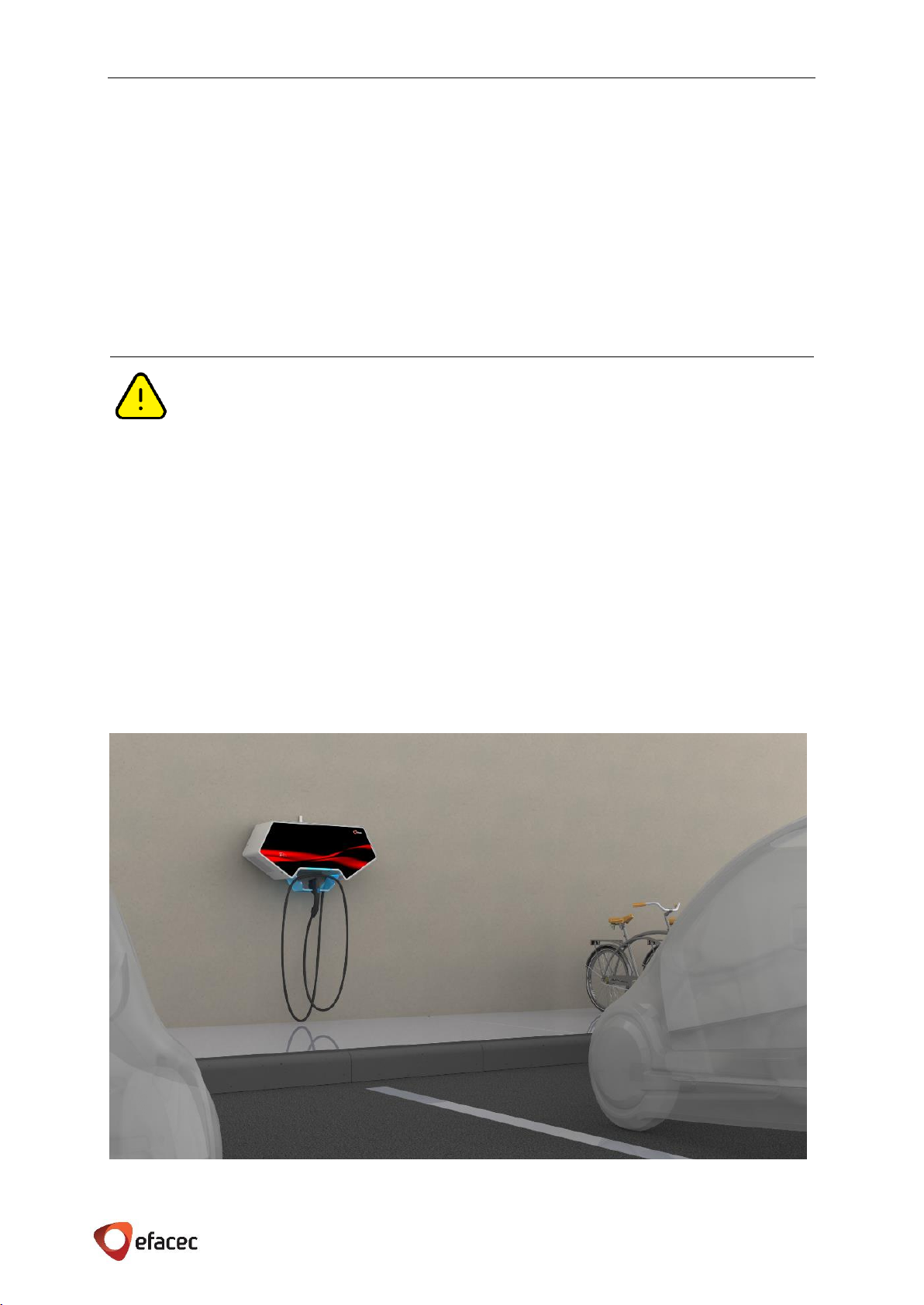
EFAPOWER EV-QC24S was intended to be placed as showed in the Figure 4.
Figure 4 - EFAPOWER EV-QC24S placing orientation
E F A P O W E R EV- Q C 2 4 S - I N S T A L L A T I O N A N D U S E R M A N U A L
8 | 28
Even though non-conductive dust does not influence the system’s operation, it may however, with excessive
accumulation, not allow proper cooling, thereby limiting the equipment’s thermal capabilities. Consequently,
dust accumulation must be avoided in order to guarantee a better thermal performance.
Conductive dust and acid vapors must be kept away from the Quick Charger.
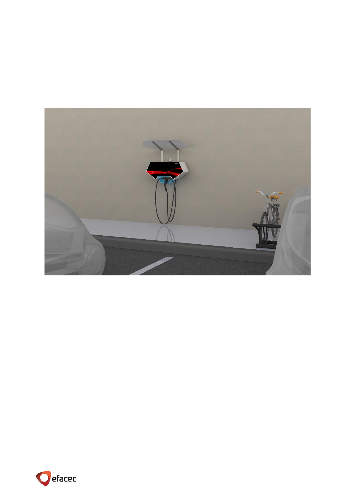
On locations with harsh weather conditions (high temperatures, heavy dust, snow and/or very low temperatures)
it’s recommended to provide additional protection, either inside a building or a shelter, or providing a protection
roof for the Unit. See example in Figure 5.
Figure 5 - EFAPOWER EV-QC24S with shelter
5.1.2 SITE VERIFICATION AND INSPECTION
✓Check if the installation of the Quick Charger is not planned to be made closer than 6,1m (20 feet) of an
outdoor motor fuel dispensing device;
✓Check if the access passages to the Quick Charger Station layout site are not blocked in order to allow its
transportation;
✓Check if Quick Charger Station layout site is compliant with the specified clearance around the cabinet.

E F A P O W E R EV- Q C 2 4 S - I N S T A L L A T I O N A N D U S E R M A N U A L
9 | 28
5.2 SITE PREPARATION
Once the local conditions have been verified, it is time to prepare the site for the installation of the EFAPOWER
EV-QC24S.
5.2.1 UPSTREAM WIRING INFORMATION
Depending on the configuration of the EFAPOWER EV-QC24S, it may have different wiring schemes as
represented in the following three figures:
CE MARKED UNITS:
▪Three phase input connection for CE marked unit:
This installation requires dedicated 50A circuit breaker 3P C curve, which shall be physically located
according to the local electrical codes.The wiring shall be done as shown above and a triple shunt
(supplied with the unit) shall be placed across neutral terminal blocks, represented in orange (X1.4,
X1.5and X1.6).
ETL MARKED UNITS:
▪Three phase input connection for ETL marked unit:
This installation requires a dedicated 100A circuit breaker 3P C curve, which shall be physically located
according to the local electrical codes. The wiring shall be done as shown above and three shunts
(supplied with the unit) shall be placed across phases terminal blocks, represented in orange (X1.1 and
X1.6; X1.2 and X1.3; X1.4 and X1.5).
Figure 6 –EFAPOWER EV-QC24S Three phase connection for CE marked unit
Figure 7- EFAPOWER EV-QC24S Three phase connection for ETL marked unit
X1.1
X1.2
X1.3
X1.4
X1.7
X1.2
X1.1
X1.4
X1.7
X1.5
X1.6
X1.3
X1.5
X1.6

E F A P O W E R EV- Q C 2 4 S - I N S T A L L A T I O N A N D U S E R M A N U A L
10 | 28
▪Single phase input connection for ETL marked unit:
This installation requires a dedicated 150A circuit breaker 2P C curve, which shall be physically located
according to the local electrical codes. The wiring shall be done as shown above and two triple shunts
(supplied with the unit) shall be placed across phase terminal blocks, represented in orange (X1.1, X1.2,
and X1.3, and also across X1.4, X1.5, and X1.6).
NOTES
In areas with frequent thunder storms, Efacec recommends adding transient voltage surge
suppression (TVSS) at the service panel for all circuits.
It is necessary to install a residual-current device (RCD) in the upstream installation switchboard of the
EFAPOWER EV-QC24S to assure protection.
Figure 8- EFAPOWER EV-QC24S Single phase connection for ETL marked unit
X1.7
X1.1
X1.4
X1.2
X1.3
X1.5
X1.6

E F A P O W E R EV- Q C 2 4 S - I N S T A L L A T I O N A N D U S E R M A N U A L
11 | 28
5.2.2 SURFACE PREPARATION
This Charging Station must be fixed to a wall by a mounting plate.
5.2.3 RESOURCES FOR INSTALLATION
The following resources will be needed for installation of the EFAPOWER EV-QC24S:
Fasteners:
▪6 (six) stainless steel hex spacers M8 Male/ M8 Male, with matching nuts and washers –(supplied with the
EFAPOWER EV-QC24S)
▪1 (one) mounting plate –(supplied with the EFAPOWER EV-QC24S)
▪For wall mount anchor:
•Concrete wall: 7 (seven) screws M8, or
•Drywall: 4 (four) anchors (5/16’’ dia. (M8) lag screws) in studs and 3 (three) drywall anchors heavy-
duty
Cables for input wiring:
▪For three phase CE marked units, the cross section of the wires shall be not less than 10mm2and according
local codes.
▪For three phase ETL marked units, use 4AWG, 90 °C copper wire, and according local codes.
▪For single phase ETL marked units, use 1AWG, 90 °C copper wire, and according local codes.
End terminals for input wiring by Unit:
▪For three phase CE marked units, 5 (five) terminal-ends for cable up to 35mm2(3phases + neutral +
protective ground), or
▪For three phase ETL marked units, 4 (four) terminal-ends for cable up to 35mm2(3phases + protective
ground), or
▪For single phase ETL marked units, 3 (three) terminal-ends for cable up to 35mm2(phase (2 wires) +
protective ground)
Tools:
▪Socket and wrench - for wall mount
▪Crimping tool - for power and earth cables
▪Torque screwdriver with flat blade - for input terminal blocks
5.2.4 SITE VERIFICATION AND INSPECTION
✓Check if Quick Charger has the appropriate upstream protection depending on the charger’s input power
configuration.
E F A P O W E R EV- Q C 2 4 S - I N S T A L L A T I O N A N D U S E R M A N U A L
12 | 28
5.3 HANDLING AND PLACING
Before installing stations
The instructions provided in this manual assume that the appropriate wiring, circuit protection, and
metering are in place at the installation location.
To assist in the process of preparing the installation site, it is recommended that before you begin
installing the Quick Charging Station, you thoroughly review the contents of this document to
familiarize yourself with the required installation steps.
In case of any doubt regarding items described in this guide, please contact us at:
5.3.1 PACKAGING
EFAPOWER EV-QC24S is shipped in a package with the three power converters outside the unit for an easier handling
and placing.
5.3.2 VISUAL INSPECTION
✓Check if the exterior packaging has been damaged by mechanical impacts or any accidents during
transportation
✓If applicable, check if the exterior cover of the EFAPOWER EV-QC24S is in perfect condition
✓Check if the interior of the Quick Charger Station is clean
✓Check for proper Quick Charger Station protective ground connection point, which should be
interconnected with the low voltage switchboard ground connection during the installation
5.3.3 HANDLING
Due to its width [1105mm (43.5in)], it is recommended that 2 persons work together to place the unit.
5.3.4 ASSEMBLY/ PLACING INSTRUCTIONS
Access to the EFAPOWER EV-QC24S controls and commands, including the button and the card reader, must
comply with local codes and ADA requirements, which includes being less than 1200mm (48”) off the ground.
ALL SERVICING MUST BE PERFORMED ONLY BY QUALIFIED PERSONNEL. DO NOT ATTEMPT TO SERVICE THE
EFAPOWER EV QC24S QUICK CHARGING STATION YOURSELF.
DO NOT REMOVE THE COVER WHILE THE EFAPOWER EV QC24S QUICK CHARGING STATION IS ENERGIZED.
BY REMOVING THE EFAPOWER EV QC24S QUICK CHARGING STATION COVER, YOU RUN THE RISK OF
EXPOSURE TO DANGEROUS VOLTAGES!
Rua Eng.º Frederico Ulrich - Apartado 3078
4471-907 MOREIRA MAIA - PORTUGAL
Tel: (+351) 229403241 - Fax: (+351) 229403209
apvsa@efacec.com
www.electricmobility.efacec.com
2725 Northwoods Parkway, Ste. B
Norcross, Georgia 30071 USA
Tel: (1) 470 395-3648 -
Fax: (1) 770 446 8920
support.e[email protected]om
www.electricmobility.efacec.com

E F A P O W E R EV- Q C 2 4 S - I N S T A L L A T I O N A N D U S E R M A N U A L
13 | 28
5.3.4.1 MOUNTING ON THE WALL
Each unit must be installed by using the mounting plate and 7 (seven) M8 screws. Length must comply with local
codes. While a concrete wall for installation is preferred, installation on a drywall will be acceptable if 4 anchors
(5/16’’ dia. (M8) lag screws) are in studs and if the remaining drywall anchors are heavy-duty.
Mounting steps:
1Attach the mounting plate to the wall (use the drilling layout template)
This figure represents the height that the mounting plate must be placed.
To facilitate the wall mounting, a drilling layout template in 1:1 scale is supplied with the unit and the
next steps should be followed:
1Place the drilling template according to the illustration below;
2Remove the adhesive on the upper corners;
3Mark the holes (There are 4 specific holes, marked with circles, for mounting in drywall that
should match with most stud center-to-center distances.)
2
1
3
2
E F A P O W E R EV- Q C 2 4 S - I N S T A L L A T I O N A N D U S E R M A N U A L
14 | 28
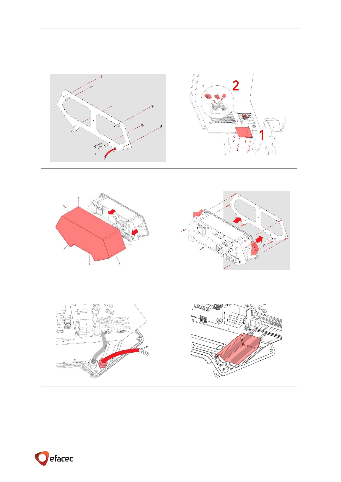
2Install the mounting plate on the wall with M8
screws. Route input cable up to the bottom of
the mounting plate (500 mm of free cable)
3Remove left side cover plate and unplug the
three connectors
4Remove the outer housing cover
5Place the unit on the mounting plate
6Guide the cable throught the grommet
7Place the protection for input and output cables
8Connect Protective Ground
(refer to Chapter 5.3.4.3)
9Switch on Circuit Breakers
(refer to Chapter 6.2)
E F A P O W E R EV- Q C 2 4 S - I N S T A L L A T I O N A N D U S E R M A N U A L
15 | 28
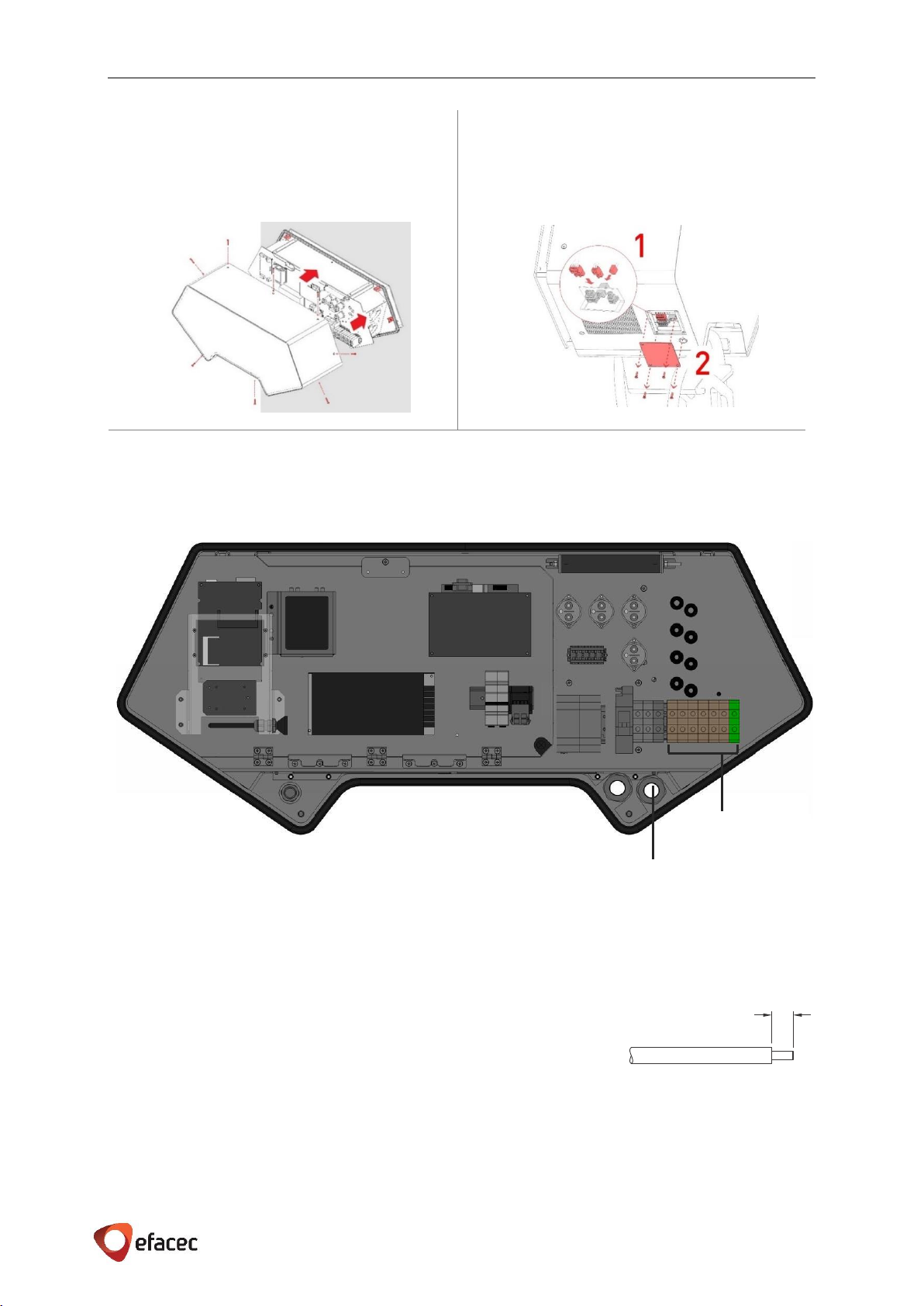
10 Place the outer housing cover. Some pressure
may need to be applied to the outside cover in
order to align the cover mounting holes and
insert the M6x35 flat head screws
11 Plug in the three connectors and place the left
side cover plate with M4 hexagon socket
countersunk head screws
5.3.4.2 POWER CABLES CONNECTIONS
The connection to the AC input terminals of each EFAPOWER EV-QC24S is carried out through the bottom of the
unit as shown below:
X1 MUST BE CONNECTED (35mm2terminal blocks).
Depending on the configuration, different wiring will be applied. Please refer to Chapter 5.2.1 Upstream Wiring
Information
Strip wires 18 mm (0.71”), crimp the end terminal and insert into the terminal block as shown, and tighten screws
between 4 N.m (35.4 inch-lbs) and 5 N.m (44.3 inch-lbs).
Strip length 0.71”
18mm
X1
Input cable entrance
Figure 9 - EFAPOWER EV-QC24S Interior front view
E F A P O W E R EV- Q C 2 4 S - I N S T A L L A T I O N A N D U S E R M A N U A L
16 | 28
IMPORTANT:
▪Always requires an upstream protection. Please refer to Chapter 5.2.1 Upstream
Wiring Information to see the appropriate protection depending on the unit
configuration.
▪Use copper conductors only
▪Before starting to work on the Quick Charger Station, connect the ground wire to the
ground terminals of the Quick Charger Station
▪In areas with frequent thunder storms, we advise to add transient voltage surge suppression
(TVSS) at the service panel for all circuits
5.3.4.3 POWER CABLES CONNECTIONS
The metallic structure of the rectifier system is connected to the protective ground connection, which should be
interconnected with the low voltage switchboard ground connection.
To assure this interconnection, X1 GROUND MUST BE CONNECTED (35mm2terminal block).
The protective earth cable must have a cross section of at least of 16 mm2 (#6AWG) or according to local codes.
6START-UP
6.1 VERIFICATION AND INSPECTION
✓Check if the bolts of the AC and protective ground cables of the Quick Charging Station are correctly
tightened to the specified torque
✓Check the resistance between the Quick Charger protective ground and the low voltage switchboard
ground connection; the value must be according to local codes
✓Before switching ON all the fuses and circuit breakers, check the supply voltage between lines which,
depending on the unit configuration, must be:
- Three phase for CE marked Units - 400V ± 10% 50Hz
- Three phase for ETL marked Units - 208V ± 10% 50Hz
- Single phase for ETL marked Units - 240V ± 10% 50Hz
✓At this stage, whenever the Unit shall be integrated with a Network Management System, Efacec must
already have the following information:
✓For Unit configuration: Station(s) ID and Central Management Endpoint
✓For Router configuration: APN and PIN, Username and Password (if applicable)
6.2 SWITCH ON
BEFORE ATTEMPTING TO INSTALL OR START UP THE EFAPOWER EV-QC24S QUICK CHARGING STATION THE
USER MUST ENSURE THAT THE SAFETY INSTRUCTIONS IN THIS MANUAL HAVE BEEN CAREFULLY READ AND
OBSERVED BY TECHNICALLY COMPETENT PERSONNEL.
KEEP THIS MANUAL WITH THE EFAPOWER EV-QC24S QUICK CHARGING STATION FOR FUTURE REFERENCE.
E F A P O W E R EV- Q C 2 4 S - I N S T A L L A T I O N A N D U S E R M A N U A L
17 | 28
THIS EFAPOWER EV-QC24S QUICK CHARGING STATION MUST NOT BE STARTED OR PUT INTO USE WITHOUT
HAVING BEEN COMMISSIONED BY A FULLY TRAINED AND AUTHORIZED PERSON
ALL SERVICING MUST BE PERFORMED ONLY BY QUALIFIED PERSONNEL. DO NOT ATTEMPT TO SERVICE THE
EFAPOWER EV-QC24S QUICK CHARGING STATION YOURSELF.
DO NOT REMOVE THE COVER WHILE THE EFAPOWER EV QC24S QUICK CHARGING STATION IS ENERGIZED.
BY OPENING THE EV-QC24S QUICK CHARGING STATION’S COVERS YOU RUN RISK OF EXPOSURE TO
DANGEROUS VOLTAGES!
IN CASE OF ANY KIND OF DOUBT REGARDING THIS, PLEASE CONTACT:
EFACEC WILL ASSUME NEITHER RESPONSIBILITY NOR LIABILITY DUE TO INCORRECT OPERATION OR
MANIPULATION OF THE EFAPOWER EV-QC24S QUICK CHARGING STATION.
EFACEC HAS TAKEN EVERY PRECAUTION TO PRODUCE AN ACCURATE, COMPLETE AND EASY TO UNDERSTAND
MANUAL AND WILL THEREFORE ASSUME NO RESPONSIBILITY NOR LIABILITY FOR DIRECT, INDIRECT OR
ACCIDENTAL PERSONAL OR MATERIAL DAMAGE DUE TO ANY MISINTERPRETATION OR UNDESIRED MISTAKES
IN THIS MANUAL.
THIS MANUAL MAY NOT BE COPIED NOR REPRODUCED WITHOUT PRIOR WRITTEN PERMISSION OF EFACEC
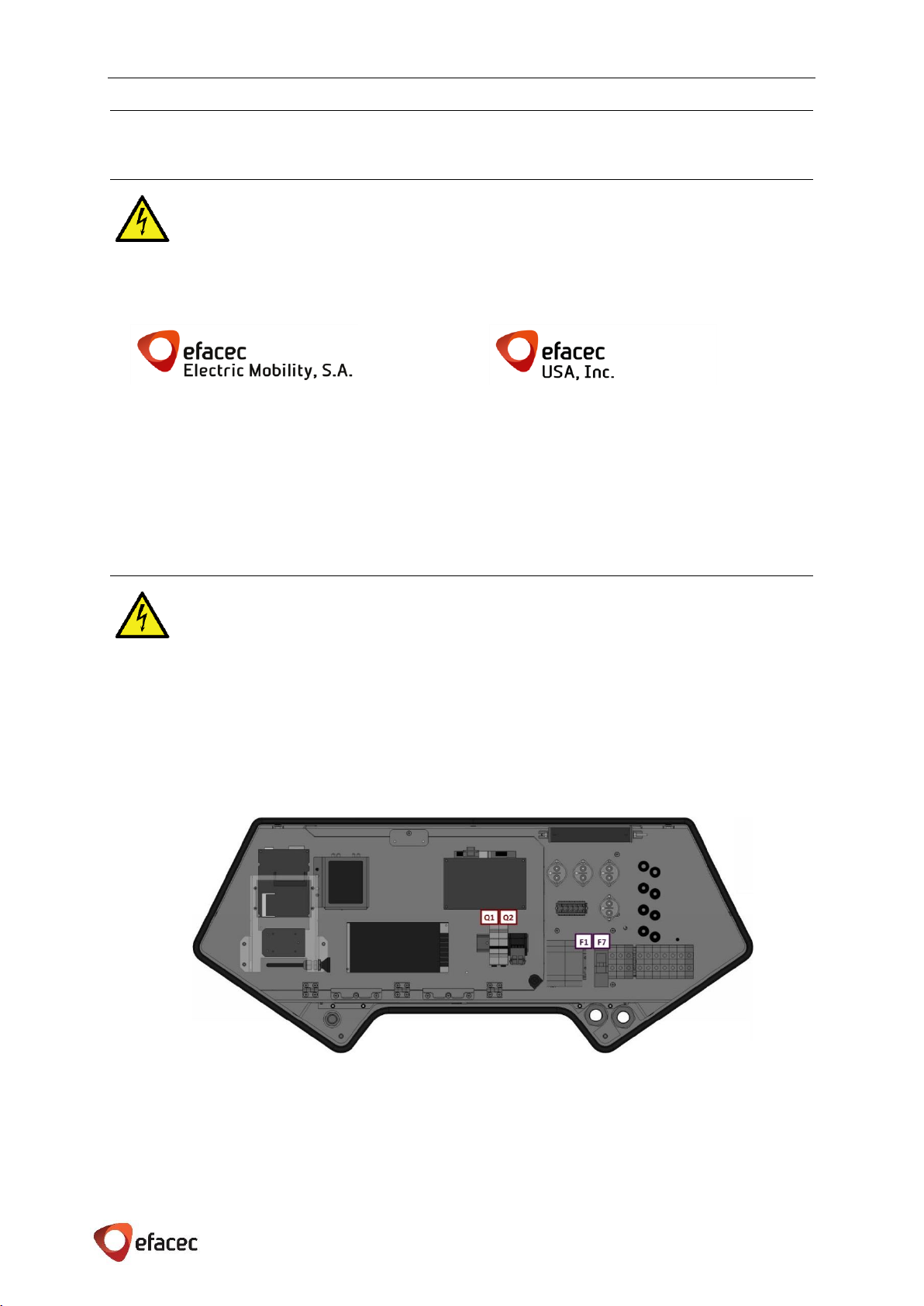
✓Switch on all the fuses and circuit breakers in the EFAPOWER EV-QC24S:
Fuses: F1, F7
Circuit Breakers: Q1 (electronics power supply), Q2 (cold option)
Figure 10 –EFAPOWER EV-QC24S components layout
Rua Eng.º Frederico Ulrich - Apartado 3078
4471-907 MOREIRA MAIA - PORTUGAL
Tel: (+351) 229403241 - Fax: (+351) 229403209
apvsa@efacec.com
www.electricmobility.efacec.com
2725 Northwoods Parkway, Ste. B
Norcross, Georgia 30071 USA
Tel: (1) 470 395-3648 -
Fax: (1) 770 446 8920
support.e[email protected]om
www.electricmobility.efacec.com
Table of contents
Other efacec Batteries Charger manuals


