Voith ARGO HYTOS RPE4-10 User manual

Instructions for use_RPE4-10_14039_1en_05/2023
Page 1
www.argo-hytos.com
ARGO-HYTOS s.r.o.
Dělnická 1306, CZ 543 01 VRCHLABÍ
The following is the authorised translation of original operating instruction RPE4-10 no. 14039_1cz_05/2023,
vydaný výrobcem:
Important! Read the instructions before using the product.
Save the instructions for future reference.
If the operating instructions are lost, new ones can be found on the ARGO-HYTOS website www.argo-hytos.com
4/2 and 4/3 SPOOL, HYDRAULIC DIRECTIONAL CONTROL VALVE with
BODY AND CONNECTION PATTERN ACCORDING TO ISO 4401
RPE4-10
INSTRUCTIONS FOR USE OF THE PRODUCT
EN

Instructions for use_RPE4-10_14039_1en_05/2023
Page 2 www.argo-hytos.com
EU PROHLÁŠENÍ O SHODĚ
EU DECLARATION OF CONFORMITY
EU-KONFORMITÄTSERKLÄRUNG
Výrobce / Manufacturer / Hersteller: ARGO-HYTOS s.r.o.
Adresa / Address / Adresse: Dělnická 1306
CZ – 543 15 VRCHLABÍ
Česká republika / Czech Republic / Tschechische Republik
Identifikační číslo (DIČ)/ Ident. No. / Ident. Nr.:
CZ47452498
F12-050.4
Výrobek / Product / Erzeugnis:
C14B*; C19B*; C22B*; C31A* DC/AC C14B*; C19B*; C22B*; C31A*
Hx 8007
Název / Name / Bezeichnung
Typ / Type / Typ
JS / Size / NG
Katalog / Catalog
ue
Účel použití / Goal of the use / Zweck
der Verwendung:
Cívka ovládacího elektromagnetu sloužíci k ovládání hydraulických prvků.
Coil for operating solenoids that is prodetermined for controlling hydraulic components.
Spule für Magnete zun Steuerung hydraulische Ventilen.
Tímto prohlašujeme, že výrobek splňuje požadavky níže uvedených zákonných předpisů a technických norem a je za
podmínek obvyklého a určeného použití bezpečný.
We declare herewith that the product meets requirements of the subsequently designated laws and technical standards and
is safe under conditions of the usual and intended use.
Wir erklären hiermit, dass das Erzeugnis mit den nachfolgend bezeichneten Rechtsvorschriften und technischen Normen
übereinstimmt und unter den Bedingungen der gewöhnlichen und bestimmten Verwendung sicher ist.
Směrnice
EU /
E
U
Directives / E
U
-
Richtlinien
2014/35/EU The harmonisation of the laws of Member States relating to the making available on the market of
electrical equipment designed for use within certain voltage limits.
Richtlinie zur Harmonisierung der Rechtsvorschriften der Mitgliedstaaten über die Bereitstellung
elektrischer Betriebsmittel zur Verwendung innerhalb bestimmter Spannungsgrenzen auf dem Markt.
2014/30/EU The harmonisation of the laws of the Member States relating to electromagnetic compatibility
Richtlinie zur Harmonisierung der Rechtsvorschriften der Mitgliedstaaten über die elektromagnetische
Verträglichkeit
2011/65/EU The restriction of the use of certain hazardous substances in electrical and electronic equipment.
B
eschränkung
der V
erwendung bestimmter gefährlicher Stoffe in Elektro
-
und Elektronikgeräte
n
2015/863 /EU Amending Annex II to Directive 2011/65/EU of the European Parliament and of the Council as regards
the list of restricted substances
Änderung von Anhang II der Richtlinie 2011/65/EU des Europäischen Parlaments und des Rates
hinsichtlich der Liste der Stoffe, die Beschränkungen unterliegen
Technické normy a předpisy / Technical standards / Technische Normen und Vorschriften:
ČSN EN ISO 12100:2011; ČSN EN ISO 9227:2017, ČSN EN 60529:1993+A1:2001+A2:2014+Opr.1:2019,
ČSN EN 60664-1 ed.2:2008, ČSN EN 60204-1 ed.3:2019, ČSN EN 61000-6-2 ed.3:2006+změna A1:2019;
ČSN EN 61000-6-3 ed.2:2007+A1:2011+ Opr.1:2013; ČSN EN 61000-6-4 ed.2:2007+A1:2011;
EN 50581:2012 (RoHS)
Upozornění: / Warning: / Beachtung: (1)
AC cívka nevyhovuje podmínkám v souladu s mezinárodní normou EN 61000-6-3:2007. Výrobek je určen pouze
k začlenění do jiného strojního zařízení tak, že vznikne strojní zařízení stanovené k posuzování shody. Strojní zařízení
nesmí být uvedeno do provozu, dokud nebude vydáno prohlášení o shodě tohoto zařízení.
AC coil not satisfy of conditions according to international standard EN 61000-6-3:2007. The product is determined only
for incorporation into another machine equipment in such a way that some new machine equipment for conformity
examination be created. The machine equipment must not be put in the operation until conformity declaration of this
machine equipment.
AC Spulen entsprechen nicht der internationalen Norm EN61000-6-3: 2007. Das Erzeugnis ist bestimmt nur zur
Eingliederung in eine andere Maschineneinrichtung auf solche Weise, dass eine neue zur Konformitätsbeurteilung
vorgesehene Maschineneinrichtung entsteht. Die Maschineneinrichtung darf nicht in Betrieb eingesetzt werden, solange
eine Konformitätserklärung dieser Maschineneinrichtung nicht herausgegeben ist.
Vrchlabí,
3
.
5
.20
2
3
Ing.
Tomáš Vatras
Místo a datum vydání /
Place and date of issue /
Ort und Datum der Ausstellung:
Vedoucí konstrukce ventilů /
R&D valves manager /
R&D Ventile manager:
Podpis /
Signature /
Unterschrift:

Instructions for use_RPE4-10_14039_1en_05/2023
Page 3
www.argo-hytos.com
Contents of the instructions for use
Chapter Page
Declaration of Conformity 2
Overview of signal words and warning signs used in the text 4
Overview of symbols and signs used in the text 4
Glossary of technical terms used 4
1. Product use 4
2. Product use risks and limitations 5
3. Product description 6
3.1 Materials used 6
3.2 Surface corrosion protection 6
3.3 Basic technical parameters 7
3.4 Working fluid 7
3.5 Performance characteristics 7
3.6 Pressure loss depending on volume flow 7
3.7 Spool position sensor 8
3.8 Legal regulations and standards 9
4. Product modification 9
4.1 Ordering code 9
4.2 Coil electrical connection connector types 10
4.3 Manual emergency valve control 11
4.4 Spool adjusting speed control 11
5. Target group of users 12
6. Instructions for use broken down by product life stages 12
6.1 Product transportation and storage 12
6.2 Product Installation 12
6.2.1 Valve assembly 12
6.2.2 Coil connector positioning 13
6.2.3 Electrical connection of valve and sensor 13
6.3 Commissioning 14
6.4 Normal Operation 14
6.5 Extraordinary and emergency situations 14
6.6 Repairs carried out by skilled persons 15
6.6.1 Dismantling the valve and replacing the seal on the valve connection surface 15
6.6.2 Replacing the electromagnet coil 15
6.7 Product Maintenance 16
6.7.1 Ongoing checks 16
6.7.2 Checking the function of the position sensor 16
6.8 Supplied spare parts 16
6.9 Product disposal 17
7. Manufacturer contact information 17
Related documents:
Document GI 0060: General Information for the use of products
Product catalogue HC 4039: 4/2 and 4/3 Electromagnetically controlled distributor RPE4-10
Product catalogue HC 8007: Coils for valve control electromagnets
Product catalogue HC 8008: Connectors according to EN 175301-803, shape A and metric connectors M12
Spare parts catalogue SP 8010: Spare parts catalogue

Instructions for use_RPE4-10_14039_1en_05/2023
Page 4 www.argo-hytos.com
List of other symbols and signs used in the text
Symbol, sign Description of the meaning of the symbol, sign
AC Designation for alternating current, voltage
DC Designation for direct current, voltage
FMP, FKM Fluoroelastomer (synthetic rubber)
NBR Rubber used for the manufacture of seals
PA Polyamide
PE Polyethylene
Glossary of technical terms used
›A hydraulic mechanism is a mechanism in which energy is transferred by the pressure energy of the working fluid
›The volumetric flow rate Q is the amount of fluid, in volume units, that flows through a given flow cross-section per unit time (m3s-1 in SI units,
l/min in practice)
›The control electromagnet is used for remote control of valves. The electromagnet consists of a mechanical control system, transmitting motion
to the slide, and an excitation coil, which generates a magnetic field that provides motion to the cylindrical armature inside the control system.
›The valve connection pattern describes the relative position of the channel holes and the holes for the connection bolts on the valve body base,
as defined by ISO 4401.
›A distributor is a slide valve that changes the connection of the channels in the body by moving the slide. It is used in hydraulic circuits to change
the direction of movement of a piston in a cylinder or the direction of rotation of the output shaft of a rotary hydraulic motor or to block the flow
of fluid and stop appliances.
›The slide position sensor is a non-contact inductive sensor that responds to the presence of a ferromagnetic core, firmly mechanically connected
to the slide.
›The valve nominal diameter (DN, NG) indicates the flow rate of the valve, which corresponds to the flow rate of a straight pipe with a specified
internal diameter (DN). For example, the valve nominal diameter DN 06 means that a pipe with an internal diameter of d = 6 mm should be used
for its connection.
›The distributor slide is the key control element moving in the valve body hole. The collars of the slide close / open the individual channels.
›Pressure is the force acting on a unit area (the SI unit is Pascal (1 Pa = Nm-2), in practice 1bar = 0.1MPa).
›Power in hydraulics is calculated as the product of pressure and volume flow. The limit power curves indicate the limit combinations of pressure
and volume flow at which reliable valve function is still ensured.
›4/2, 4/3 is an abbreviated designation of the valve description. Four means that it is a four-way valve, i.e. having four channels (P-pressure, T - return,
leading to the tank, A and B leading to the appliance). Two (three) means that it is a two-position (three-position) valve, when the slide takes two
(three) positions. The basic one, in which it is held by springs, and the working one, in which it is moved by the force of an electromagnet.
1. Product use
The RPE3-10 valve is a hydraulic four-way two-position or three-position slide distributor with body, directly controlled by electromagnet(s),
designed for connection to a plate with DN 10 connection pattern according to ISO 4401. The product is designed to control the direction of
movement of the output member of the appliance, or to stop it.
The valve with built-in slide position sensor(s) is intended for use in systems with increased requirements for reliability and safety, e.g. control
hydraulic circuits of presses, plastic injection presses, molding machines, construction machines, etc.
An overview of signal words and warning signs used in the text
DANGER Signal word combined with a warning sign used to signify that a dangerous situation which could result in
death or serious injury is imminent.
WARNING Signal word combined with a warning sign used to signify a potentially hazardous situation which, if not
avoided, may result in minor or moderate injury.
CAUTION Signal word combined with a warning sign used to signify the occurrence of a potentially dangerous situation
that could result in death or serious injury if not avoided.

Instructions for use_RPE4-10_14039_1en_05/2023
Page 5 www.argo-hytos.com
DANGER
Maximum operating pressure
The valve may be used for a maximum working fluid pressure of 350 bar in the P, A, B channels and 210 bar in
the T channel. Exceeding the maximum pressure can damage the valve and if the compressive strength value of
525 bar in the P, A, B or 315 bar in the T channel is exceeded, the valve will rupture.
DANGER
Limited hydraulic power
In the catalogue and in the instructions for use of the product, there is a graph with the limit powers for
individual connections – types of the slide valves. Power means the mutual combination of operating pressure
and volume flow. If the limit power curves are exceeded, there is a risk of unreliable function or loss of product
function.
WARNING
Tightening the valve
The valve may be mounted on a connection surface with corresponding flatness and roughness with the
connection pattern DN 10 according to ISO 4401 (see p. 6.21 Valve assembly). The four fastening screws
M6x45 DIN 912-10.9 must be tightened crosswise with a tightening torque of 14+1 Nm. Use original screws
with increased tensile strength. Failure to comply with the conditions of correct fastening risks the release
of the valve by pressure and leakage of the working fluid.
CAUTION
Maximum operating temperature and tightness
The maximum operating temperature must not exceed the temperature range for the given type of seal
material, otherwise there will be loss of tightness and leakage of the working fluid.
Seal material NBR: -30 to +80 °C
FPM (Viton®) seal material: - 20 to + 80 °C
CAUTION
Maximum operating temperature and function
The maximum operating temperature of the fluid must not exceed 80 °C and the maximum ambient tempera-
ture must not exceed 50°C. This combination of temperatures determines the maximum winding temperature
of the electromagnet coil. When the temperature is exceeded, the resistance of the coil winding increases and
the strength of the electromagnet, and thus the hydraulic performance of the valve, decreases. There is also a
risk of damage to the coil wire insulation, short circuit and loss of electromagnet function. Also, the correct
function of the position sensor is only guaranteed in the temperature range of -25 °C to 80 °C.
CAUTION
Valve surface temperature
The surface temperature of the valve including the control electromagnet can exceed 100°C due to the
temperature of the working fluid, pressure losses in the valve converted into heat and heating of the coil
winding. Do not touch the surface of the valve and electromagnet while the circuit is the operating mode or
after shutdown until it has cooled to a safe temperature. Risk of skin burns.
CAUTION
Used working fluids
The valves may only be used for normal working fluids, especially hydraulic oils.
(see chapter 3. Product description). As a working fluid, it is prohibited to use, in particular:
› water and aqueous solutions that will cause corrosion and loss of the valve function
› easily flammable or explosive fluids, the heating of which may cause a fire or explosion when passing
through the valve
› aggressive fluids (e.g. acids and hydroxides) which will damage the valve and cause loss of function.
2. Product use risks and limitations

Instructions for use_RPE4-10_14039_1en_05/2023
Page 6
www.argo-hytos.com
3.1 Materials used:
Valve body – grey cast iron
Slide – hardened steel
Compression centring springs – patented steel wire for the production of springs
Control system ring and pin – non-magnetic stainless steel with 10% nickel content in the alloy
Control system plug – brass
Control system attachment, pipe and anchor, coil shell, sensor body and flange – steel
Coil body, coil encasement in casing, coil connector base – polyamide (PA)
Coil winding – enamelled copper wire
Type plate – anodized aluminium sheet
Coil fixing nut – polyamide (PA) / closed nut (N1) – aluminium alloy
Valve seal – NBR, FPM (depending on valve type)
The materials used are not included in the lists of prohibited and mandatorily documented substances of Directive 2011/65/EU (RoHS) and EU
Regulation No. 1907/2006 (REACH).
12 2 34
5 6
3. Product description
The hydraulic distributor consists of a cast iron body with a DN 10 connection pattern according to ISO 4401 on the base (1). A hardened steel slide
moves inside the body, which is held in the basic position by centring springs. The slide is moved to the working position by the power of the control
electromagnet (2). The slid closes / connects the channels in the valve body with its collars (see the overview of slide connections). We classify the
distributor in the group of valves for controlling the direction of liquid flow. That is, it changes the direction of movement of the output member of
the appliance, or stops it.
The electromagnet (2) consists of a mechanical part – a control system, which transmits movement to the slider, and a coil, which creates a strong
magnetic field by passing current through the coil winding. The coil is fixed on the control system with a plastic nut (3). The coils are connected to
the electrical supply via the connector (4).
In the type of valve with a slide valve position sensor, a non-contact inductive sensor (5) is mounted between the body of the hydraulic part and the
control electromagnet. The sensor responds to the position of the steel core firmly connected to the slide. The sensor is connected using a four-pin
connector with M12x1 thread (6).
3.2 Surface corrosion protection:
In the standard version, the valve body is phosphated, the outer surface of the steel parts is galvanized with 240 h corrosion protection in NSS
according to ISO 9227. Phosphating is recommended as a base layer for spraying the body with paint.
In the version with reinforced corrosion protection, the body and the outer surface of the steel parts are galvanized with 520 h corrosion protection in
NSS according to ISO 9227.
The surface protection layer does not contain hexavalent chromium Cr6+.

Instructions for use_RPE4-10_14039_1en_05/2023
Page 7 www.argo-hytos.com
3.3 Basic technical parameters
Parameter Unit Value
Maximum pressure in channels P, A, B bar (PSI) 350 (5080)
Maximum pressure in output channel T bar (PSI) 210 (3050)
Maximum volumetric flow rate through the valve l/min (GPM) 140 (37)
Working fluid temperature range for NBR seal material °C (°F) -30 to +80 (-22 ... +176)
Working fluid temperature range for FPM seal material °C (°F) - 20 to +80 (-4 ... +176)
Ambient temperature range °C (°F) -30 to +50 (-22 ... +122)
Working fluid kinematic viscosity range mm2s-1 10 to 400
Required minimum working fluid purity Class 21/18/15 ISO 4406
Electromagnet coil supply voltage tolerance % of UNOM ± 10
Maximum switching frequency number/h 15,000
Lifetime cycles 107
Approximate switching time ON at a kinematic viscosity of 32 mm2s-1 ms AC: 30-40 DC 30-40
Approximate switching time OFF at a kinematic viscosity of 32 mm2s-1 ms AC: 30-70 DC 10-50
Valve weight with one electromagnet kg (lbs) 3,91 (8.62)
with two electromagnets 5,39 (11.88)
Valve weight with one electromagnet and sensor kg (lbs) 4,82 (10.63)
with two electromagnets and sensors 7,21 (15.90)
3.5 Performance characteristics, measured at viscosity ν= 32 mm2/s (156 SUS)
Limit performance curves are determined under the least favourable operating conditions, i.e. the maximum permitted temperature of the fluid and
the surroundings, and minimum control voltage (0.9 UNOM).
Spool symbol
Z11, Z51, H11, H51, P11, P51 1
R11, X11, R21 2
C11,C51 3
B11,B51 4
Y11,Y51 5
J15, J75 6
L21 7
A51 8
C21 9
80 100 120 140
(1450)
(2176)
(725)
(4351)
(5076)
(2901)
(3626)
020 40
100
150
50
300
350
200
250
60
9
8
74
6
2
5
3
1
(21.1) (26.4)(5.3) (15.9)(10.6) (31.7)
(40.0)
Operating pressure p [bar (PSI)]
Flow Q [l/min (GPM)]
Operating limits for maximum hydraulic power at rated temperature and
supply voltage equal to 90% nominal.
80 100 120 140
020 40
6
2
60
(21.1) (26.4)(5.3) (15.9)(10.6) (31.7)
(40.0)
1
2
3
4
5
6
10
14
18
22
(87)
(29)
(145)
(203)
(261)
(304)
Direction of flow Direction of flow
Spool symbol P-A P-B A-T B-T P-T P-A P-B A-T B-T P-T
Z11, P11, Y11,
R11, X11, B11 1 1 2 2 C11 4 3 4 5 1
Z51, Y51, B51 1 2 C51 4 5 1
H11 1 1 2 2 1 L21 1 1 1 2 2
H51 1 2 1 R21 1 1 1 3
P51 1 2 J15 1 1 2 3
J75, A51 1 1 C21 6 6 6 6 4
Flow Q [l/min (GPM)]
Pressure drop Δp [bar (PSI)]
3.6 Pressure drop related to flow rate, measured at viscosity ν= 32 mm2/s (156 SUS)
3.4 Working fluid
The valve is designed for common hydraulic working fluids:
mineral oils of performance classes HM and HV according to ISO 6734-4
non-flammable and difficult to ignite hydraulic fluids according to ISO 12922
environmentally acceptable hydraulic fluids according to ISO 15380
NOTICE: NBR seal material is not suitable for some working fluid groups, such as the HFD group.
In case of uncertainty, we recommend to perform a test of the mutual tolerance of the seal material and the working fluid.
CAUTION
Consult the manufacturer's technical department for performance characteristics in flow directions other than
those listed. When the liquid flows through only one channel (A or B), when the other remains closed or is only
loaded with static pressure, a significant reduction in the limiting performance characteristics can occur.

Instructions for use_RPE4-10_14039_1en_05/2023
Page 8
www.argo-hytos.com
3.7 Spool Position Sensor
S1 - Sensor wiring diagram
With closing contacts (normally open)
S4 - Sensor wiring diagram
With opening contacts (normally close)
Technical Data of the Sensor S1 (NO - switching) / S4 (NC - switching off)
Rated power supply voltage V DC 24
Power supply voltage range V DC 10 to 30
Rated current mA 200
Sensor enclosure protection EN 60529 IP67
Max. operating pressure bar (PSI) 210 (3046)
Switching frequency Hz 1000
Ambient temperature range °C (°F) -25 ... +80 (-13 ... +176)
Technical Data of the Connector
Power supply voltage range V 10 ... 30 DC
Ambient temperature range °C (°F) -25 ... +80 (-13 ... +176)
Indicator yellow LED (connector plug)
Three-Position Directional Control Valve
Solenoid Sensor
a b S1 a S1 b S4 a S4 b
0 0 1 1 0 0
1 0 0 1 1 0
0 1 1 0 0 1
2
connector
PNP sensor
PNP sensor connector
Two-Position Directional Control Valve
Solenoid S1 S4
010
101
The non-contact induction sensor is mounted in the body perpendicular to the distributor spool and its position after adjustment is marked in red.
The sensor is supplied in two versions, with closing (NO) or opening (NC) contacts. When the spool is in the basic position, secured by springs, the
sensor core firmly connected to the spool is located under the front surface of the sensor and the sensor is activated. After moving the spool with the
core to the working position by the force of the closed electromagnet, the core is moved out of the sensor's reach and the sensor is deactivated (see
switching table). The electrical connection of the sensor is ensured by means of a four-pin connector with M12x1 thread.
Technical parameters
Description of function
Switching table
4/3 distributor with two sensors - three-position4/2 distributor with one sensor - two-position
Solenoid: 0 - OFF / 1 - ON
Spool Position Sensor (S1 / S4): 0 - normally-open contact / 1 - normally-closed contact

Instructions for use_RPE4-10_14039_1en_05/2023
Page 9
www.argo-hytos.com
The valve meets the relevant requirements of legal regulations and standards as amended:
Directive 2006/42/EU On machinery / chapters used: 1.7.4 Instructions for use, Annex I Basic safety requirements
ČSN EN ISO 4413:2011 - Hydraulics – General rules and safety requirements for hydraulic systems and their components
ČSN EN ISO 13849-1:2017 – Safety of machinery – Safety of parts of control systems – Part 1: General principles for construction
Directive 2014/35/EU (LVD) On the harmonisation of the laws of the Member States relating to the making available on the market of electrical
equipment designed for use within certain voltage limits
Directive 2014/30/EU (EMC) On the harmonisation of the laws of the Member States relating to electromagnetic compatibility
Directive 2011/65/EU (RoHS) On the restriction of the use of certain hazardous substances in electrical and electronic equipment
Directive 2015/863/EU (RoHS) amending Annex II to Directive 2011/65/EU of the European Parliament and of the Council as regards the list of
restricted substances
Regulation (EC) 1907/2006 (REACH) On Registration, evaluation, authorisation and restriction of chemicals
Other regulations and standards used:
ČSN EN ISO 12100: 2011 Safety of machinery / risk analysis
ISO 4401:2005 Hydraulic fluid power – Four-port directional control valves – Mounting surfaces
ČSN EN ISO 9227:2017 Corrosion tests in artificial atmospheres – Salt spray tests / Paragraph 5.2.2 Neutral salt spray test (NSS)
ISO 20653:2013 Road vehicles — Degrees of protection (IP code) — Protection of electrical equipment against foreign objects, water and access
ČSN ISO 4406:2006 Hydraulic fluid power – Fluids – Method for coding the level of contamination by solid particles
ČSN EN 60664-1:2004 Insulation coordination for equipment within low-voltage systems – Part 1: Principles, requirements and tests
ČSN EN 61000-6-1:2007 Electromagnetic compatibility (EMC) – Part 6-1: Generic standards – Immunity for residential, commercial and light-industri-
al environments.
ČSN EN 61000-6-2:2006 Electromagnetic compatibility (EMC) – Part 6-2: Generic standards – Immunity for industrial environments
ČSN EN 61000-6-3:2006 Electromagnetic compatibility (EMC) – Part 4-3: Testing and measurement techniques – Radiated, radio-frequency,
electromagnetic field immunity test.
ČSN EN 61000-6-4:2002 Electromagnetic compatibility (EMC) – Part 6-4: Generic standards – Emission standard for industrial environments
ČSN EN ISO 9001:2015 Quality management systems
ČSN EN 82079-1: 2013 Preparation of instructions for use - Structuring, content and presentation / Part 1: General principles and detailed requirements
4. Product modification
Ordering code
RPE4 - 10 / -
E1
E2
E3
E4
E5
E12A
E13A
2
3
01200
02400
02700
20500
12060
23050
3.8 Legal regulations and standards:
An overview of possible valve modifications is described in the ordering key.
Coil control voltage and coil power connector
The coil type can be changed by the customer if he observes the safety principles during replacement and adapts the electrical parameters of the
source and the type of connector plug to the new type of coil.
The seal material cannot be changed by the user, as part of the seal is located between the valve body and the control system, respectively the
sensor body. The user must not disassemble the valve.
Other parameters, such as the type of slide, can only be selected when ordering, as they cannot be changed without disassembling the valve.
If the slider position sensor setting, indicated in red, is unintentionally lost, have the sensor readjusted by the manufacturer.
NOTICE:
Valve repairs and sensor adjustments may only be performed by the manufacturer. If the valve is disassembled by the user, the manufacturer disclaims
liability for its correct operation and sensor adjustment.
4.1 Ordering Code
Spool symbols
see the table “Spool Symbols“
Valve size No designation
A
B
Surface treatment
standard
zinc-coated (ZnCr-3), ISO 9227 (240 h)
zinc-coated (ZnNi), ISO 9227 (520 h)
No designation
N1
N2
N4
N5
N9
No designation
T0
T2
T3
No designation
V
Manual override
standard
cap nut covered
rubber boot protected
hand screw
socket head screw
without manual override
Soft-shift spool speed control
without soft-shift control
with plugged cavity for optional soft shift installation
orifice Ø0.6 mm (0.02 inch) in T line bridge
adjustable needle valve in T line bridge
Seals
NBR
FPM (Viton)
Connector
EN 175301-803-A
E1 with quenching diode
AMP Junior Timer - radial direction (2 pins; male)
E3 with quenching diode
EN 175301-803-A with integrated rectifier
Deutsch DT04-2P - axial direction (2 pins; male)
E12A with quenching diode
Number of spool positions
two positions
three positions Spool monitoring
without sensors
normally-open sensor
normally-closed sensor
No designation
S1
S4
4/2 and 4/3
directional control valve,
solenoid operated
Rated supply voltage of solenoids
(at the coil terminals)
12 V DC / 3.17 A
24 V DC / 1.73 A
27 V DC / 1.52 A
205 V DC / 0.20 A
120 V AC / 0.38 A / 60 Hz
230 V AC / 0.20 A / 50 (60) Hz

Instructions for use_RPE4-10_14039_1en_05/2023
Page 10 www.argo-hytos.com
Note:
The following items must be ordered separately, they are not part of the valve delivery:
› High-strength clamping screws M6x45 DIN 912 10.9 (see catalogue SP 8010), possibly bolts for vertical grouping (see catalogue 0020)
› Coil connector socket type EN 175301-803-A (see catalogue SP 8010)
› K02 position sensor connector socket with LED (see catalogue SP 8010)
› Inlet nozzle with a diameter of 0.5 to 4 mm into the inlet P channel (see catalogue SP 8010)
4.2 Types of coil electrical connection connectors
Type of Solenoid Coil in millimeters (inches)
Possible and preferred combinations of connector type and control voltage are listed in the HC 8007 Product Catalogue:
Coils for valve control electromagnets
Spool Symbols
Type Symbol Interposition Type Symbol Interposition
73,2 (2.88)
62 (2.44)
41,5 (1.64)
53,6 (2.11)
46,5(1.83)
52 (2.05)
E1, E2
Protection degree IP65
E3, E4
Protection degree IP67
E5
Protection degree IP65
E12A, E13A
Protection IP67 / IP69K
The indicated IP protection level is only achieved if the connector is properly mounted.
CAUTION An E5 connector with a built-in rectifier must be used for AC supply voltage to the coils.

Instructions for use_RPE4-10_14039_1en_05/2023
Page 11
www.argo-hytos.com
4.3 Manual emergency valve control
In the event of a failure of the electromagnet coil or a failure of the coil's electrical supply, the slide can be repositioned, e.g. in order to reach a safe
position of the device, using a manual emergency control. However, the valve can only be operated manually up to a pressure of 20-25 bar in the
T channel.
Manual Override in millimeters (inches)
4.4 Spool adjusting speed control
By reducing the speed of adjustment of the slide, it is possible to slow down transient events in the hydraulic circuit and prevent the occurrence of
pressure peaks.
When adjusting the slide, the working fluid is passed through the connecting channel between the spaces in front of the slide faces. The slide
adjustment speed is reduced by incorporating a nozzle (version T2) or a simple throttle valve (version T3) into the connecting channel. Throttle valve
allows smooth adjustment of movement speed. The nozzle / valve must be bleeded after installing the valve in the circuit.
(See manual “Instructions for bleeding the hydraulic damping system”)
Spool Speed Control in millimeters (inches)
Plugged cavity for optional soft-shift control
devices installation (T2, T3)
Switching
time
ON and OFF
The orifice extends the valve
shifting time. The needle valve allows continuous
adjustment of the shifting time.
120 ... 350 ms 30 ... 2000 ms
The switching times shown are valid for viscosity ν= 32 mm2/s (156 SUS) and nominal voltage.
They depend on working pressure and flow rate of the directional control valve.
5
M10x1
Designation T0 - Plug VSTI M10x1 Designation T2 - Orifice ∅ 0.6 (0.02) Designation T3 - Needle valve
Mooving of spool
Flow of fluid
106 (4.17)
111 (4.37)
123,5 (4.86)
128 (5.04)
106 (4.17)
112,5 (4.43)
No designation
- standard
Designation N1
- cap nut covered
Designation N2
- rubber boot
protected
Designation N4
- hand screw
Designation N5
- socket head screw
size 3
Designation N9
- without manual
override

Instructions for use_RPE4-10_14039_1en_05/2023
Page 12
www.argo-hytos.com
6. Instructions for use broken down by product life stages
As standard, the valve is packed in a vacuum shrinkable PE film and protected against moisture and dust. An identification plate is affixed to the
package. Products should only be stored for the necessary time at a temperature of 0 to +30 °C in a dry place with a relative humidity of up to 65%.
After a longer period of storage, we recommend checking that the product is not damaged by corrosion, replacing the external seals and flushing the
product with clean oil before connecting it to the hydraulic circuit.
6.1 Product transportation and storage
› Check the correctness of the valve type on the identification plate.
› Open the packaging with scissors and carefully remove the valve from the package.
› Unpack the valve in a clean place and prevent contamination of the valve.
› The packaging is made of PE and may be slightly contaminated with residual hydraulic oil from the valve. Dispose of the packaging in accordance
with applicable environmental regulations.
› Just before mounting the valve, remove the plastic shipping plate from the connection pattern at the base of the body, check the five sealing rings
for completeness and integrity, and check the connection surface for cleanliness. Replace damaged rings with new ones (see spare parts). You can
return an undamaged shipping plate to the manufacturer.
6.2 Product Installation
5. Target group of users
All the activities relate to the valve, especially the installation and adjustment of cracking pressure, require technical expertise and experience in the
field of hydraulics. The minimum required level of professional competence is CETOP level 2. This level is generally defined as the performance of
various activities that require an understanding of technical factors and contexts. This may lead to the need of correct interpretation (e.g. tolerances,
operating methods) or to the application of various non-repetitive procedures. This may require the performance of instructions, simple analyses and
diagnostics, the ability to respond operationally to changes. Teamwork is often necessary.
The electrical connection of the electromagnet and the position sensor can only be performed by a person with the appropriate electrotechnical qualification.
It is forbidden for the following to carry out any activities related to this product:
› Minors (the exception being practical training of students under the professional supervision of a teacher)
› Without the specified professional competence
› Under the influence of alcohol and/or drugs
› Patients whose health condition could affect safety (reduced attention span and ability to react in a timely manner, excessive fatigue)
› Under the influence of drugs that have a demonstratable effect on attention and the ability to react in a timely manner
› Those with an allergy to hydraulic working fluids
6.2.1 Valve assembly
The valve is designed for mounting on a connection plate that has the required flatness and surface roughness, is provided with a DN 10 nominal
diameter mounting pattern according to ISO 4401 (ISO 4401-05-04-0-05), is undamaged and clean. The mounting position of the valve is arbitrary.
If vibrations and minor shocks are applied to the valve during operation, they must not be applied in the direction of the valve axis to avoid unintenti-
onal repositioning and increased internal volume losses.
› Orient the distributor correctly.
› Carefully place the valve on the connection plate so that the channels in the valve and in the plate are correctly aligned. Make sure that when the
valve is laid down, none of the sealing rings fall out of the recess in the body.
› Insert the four fastening screws with cylindrical head and hexagon socket M6x45 DIN 912-10.9 into the holes in the valve body.
› Gradually tighten the screws crosswise to a torque of 14+1 Nm using a size 5 inbus wrench.
CAUTION
Correct valve mounting
Failure to comply with connection plate requirements, fallen out or damaged sealing rings, contaminating
particles in the dividing plane, incorrectly tightened bolts lead to leakage of working fluid in the dividing plane.
Use original screws with defined length and increased material tensile strength.
Channels P, A, B, T - max. ∅11,2 mm (0.44 in)
13,5(0.53)
24,6(0.97)
39,7(1.56)
46(1.81)
16,7(0.66)
27(1.06)
37,3(1.47)
50,8(2)
54(2.13)
3,2(0.13)
4xM6 -6Hx15+1/18-2
T
A
A
B
P
T
B
ISO 4401-05-04-0-05
Mounting pattern for DN 10, ISO 4401-05-04-0-05 Requirements for flatness and surface roughness of the connection plate
Connection surface free from mechanical damage (indentations, etc.)
and free of dirt.
CAUTION
Slippery valve surface
The valve contains a small amount of residual oil after the hydraulic function test performed by the manufacturer.
A slippery valve surface can lead to dropping when handling, causing minor injury or damage to the valve.

Instructions for use_RPE4-10_14039_1en_05/2023
Page 13
www.argo-hytos.com
6.2.2 Coil connector positioning
The design of the electromagnet allows rotation of the electromagnet coil in the range of 360° to 90° so that the coil connector points the power
supply cable or respects the space for installation on the machine. Use the following procedure to rotate the coil:
› Loosen the coil clamping nut on the end of the control system.
› Rotate the electromagnet coil so that the coil connector points in the desired direction.
› Secure the coil position by re-tightening the nut to a torque of 6+1 Nm using a size 36 wrench.
6.2.3 Electrical connection of valve and sensor
Remove the plastic cover of the coil connector (if used according to the connector type) and the plastic cover of the position sensor connector.
For the electrical connection, use a socket compatible with the type of the connector used. Observe the correct connection of the sensor connector
pins according to the function of your control unit. (see the wiring diagram of the sensor).
CAUTION
Wiring
The electrical connection of the electromagnet to the power source and the connection of the position sensor
to the control unit may only be carried out by persons with appropriate electrical engineering qualifications.
It is forbidden to use damaged connectors or cables for electrical connection. There is a risk of electric shock
and short circuit of electrical equipment.
Plastic nut
6+1 Nm (4.4+0.7 lbf.ft)
Mounting screws 14+1 Nm (10.3+0.7 lbf.ft)
M6 x 45 DIN 912-10.9
Required surface quality of
the counterpart
Dimensions in millimeters (inches)
RPE4-103*/*E1*S
RPE4-103*/*E1
Valve with one solenoid „b“
Spool symbols X11, C11, H11 Valve with one solenoid „a“
Spool symbols R11, R21, A51, P51,Y51,
C51, B51, Z51, H51
Valve with two solenoids
RPE4-102*/*E1*S

Instructions for use_RPE4-10_14039_1en_05/2023
Page 14 www.argo-hytos.com
Electromagnet coils (type C 31)
The control electromagnet coils are designed for continuous operation (100% ED). The coils have been assessed for compliance with Directive
2014/35/EU (LVD) if the rated voltage is higher than 50 V AC or 75 V DC, Directive 2014/30/EU (EMC) and Directive 2011/65/EU + 2015/863 /EU
(RoHS). The coils are marked with the CE conformity mark on the casing. The nominal voltage values for the coil supply are indicated on the coil
casing. Fluctuations in the supply voltage are allowed within ±10% of UN.
Overview of C31 size coil types according to power supply values (see also the ordering key and catalogue HC 8007)
Type designation in the key Nominal voltage UN(at coil terminals) Nominal current IN
01200 12V DC 3.17 A
02400 24V DC 1.73 A
02700 27 V DC 1.52 A
20500 205 V DC 0.20 A
12060 120 V AC 0.38 A / 60 Hz
23050 230 V AC 0.20 A / 50 (60) Hz
To power the coils with alternating current (marked in the key 12060 and 23050), the construction type of the coil E5 with a built-in rectifier
in the connector base must be selected. Coils with a supply voltage of 205 V DC (marked in the key 20500) are intended for power supply with an
alternating current of 230 V AC / 50(60) Hz, when the rectifier is built into the socket of the connector. A lower coil voltage corresponds to a voltage
drop on the rectifier.
The position sensor is equipped with a four-pin connector with M12x1 thread. The connection of the S1 and S4 type sensor pins is indicated in the
description of the sensor (see chapter 3.7).
CAUTION
Voltage and current values
Observe the specified values of the electrical parameters for controlling the electromagnet coil and power
supply of the position sensor. Observe the sensor output parameters when designing the control unit. If the
limit parameters are exceeded, there is a risk of damage to the electrical parts of the valve and damage to the
control unit.
6.3 Commissioning
Before putting the hydraulic circuit into operation, check:
› correct tightening of the valve fastening screws
› integrity of electrical wiring and connectors
› correct fixing of the coil and sensor connector
› correct connection of the valve to the control unit
› setting the correct values of the electrical parameters on the power supply
6.4 Normal Operation
6.5 Extraordinary and emergency situations
In the event of a power failure of the hydraulic system and a drop in pressure, the slide position will not change.
In the event of a power failure, the slide is automatically reset to the initial position by the force of the centring springs. If you need to reset the
distributor slide in an emergency, e.g. to reach a safe position of the mechanism, use the emergency control (see paragraph 4.3).
Based on the results of the risk analysis, three potential defects were determined:
› External valve leakage due to seal damage associated with leakage of working fluid. If a leak is detected in the parting plane between the valve
and the connection plate, the defect can be eliminated by replacing the sealing rings. Replace the leaking valve between the body and the control
system / sensor extension with a new valve and send the defective one to the manufacturer for repair.
› Do not readjust the slide due to the defective coil. First, check that the coil is actually powered (there is no damage to the cable, control unit, or
connector). You can replace the defective coil with a new functional one after loosening the clamping nut.
› The position sensor does not give the control unit any signal about the position of the slide. First, check if the position sensor is properly connected
(there is no damage to the cable, control unit or connector). The valve with the non-functioning position sensor must be replaced.
Normal operation of the system does not require any manipulation of the valve. The valve slide is adjusted by means of the control electromagnet by
a signal from the control unit. The position sensor checks that the set position has been reached and sends a feedback signal to the control unit.
DO NOT exceed the MAXIMUM PARAMETERS, shown in table 3.3.
OBSERVE THE OPERATIONAL RESTRICTIONS AND AVOID THE RISKS , referred to in paragraph 2.
USE PROTECTIVE EQUIPMENT
When working with hydraulic fluid, it is recommended to wear safety goggles, protective rubber gloves and sturdy shoes with non-slip soles.

Instructions for use_RPE4-10_14039_1en_05/2023
Page 15
www.argo-hytos.com
CAUTION
Switching off the pressure source and relieving the circuit
In the event of an emergency, switch the power source off (pump) and relieve all parts of the hydraulic circuit,
including the hydraulic accumulators, by connecting them to the tank. Before any work on the circuit, such as
removing a valve ensure that the circuit is depressurized. Otherwise there is a risk of leakage of the working
fluid and contamination of personnel.
CAUTION
Disconnecting the electrical supply
Disconnect the electrical parts of the valve from the power supply. On the one hand, there is a risk of electric
shock, and on the other hand, unintended activation of the valve can lead to serious situations.
ENVIRONMENTAL PROTECTION
Spilled working fluid must be removed immediately, e.g. with suitable absorbents, contaminated parts of the perimeter cleaned,
contaminated objects in the vicinity cleaned or disposed of. Contaminated objects and residues of leaked working fluid must be
disposed of in accordance with the applicable environmental regulations.
FIRST AID
Contamination by hydraulic working fluid
If contamination of persons occurs, contaminated parts of clothing must be removed immediately and the skin thoroughly washed
with soap or treated with a suitable cream.
If the eyes are contaminated, flush them with clean water and seek medical attention. Seek medical attention also in case of
accidental ingestion of working fluid or skin allergic reaction to splashes of working fluid.
Electric shock
In the event of an electric shock, immediately turn off the power source, call emergency medical help and, if possible, start resuscita-
tion of the victim if they are unconscious and not breathing (cardiac massage, use of a defibrillator, etc.)
6.6 Repairs carried out by skilled persons
6.6.1 Dismantling the valve and replacing the seal on the valve connection surface
The user is entitled to replace the defective valve with a new one, replace the seal on the valve base and replace the electromagnet coil. A set of seals
and coils is supplied as spare parts.
› Make sure the circuit is depressurized and the power supply to the electrical parts is turned off.
› If the equipment has been in operation, it is necessary to let the circuit cool down to avoid burning from the circuit parts.
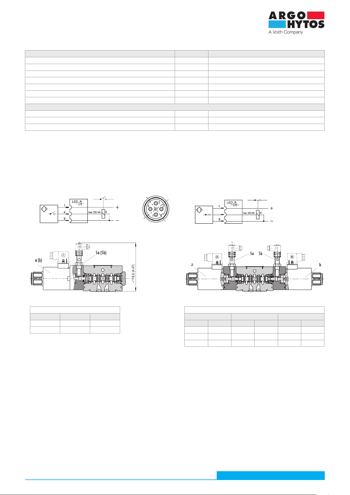
› Disconnect the coil connector socket and, for a valve with a sensor, also the position sensor connector socket. Make sure that particularly the inner
space of the sockets with contracts are not dirty and contaminated with working fluid.
› Using a size 5 inbus wrench, loosen all four M6x45 valve fastening screws one by one and remove the valve from the connection plate. Take into
account that the inside of the valve contains a residual amount of working fluid which will start to leak out after removal. We recommend that you
immediately place the valve in a prepared suitable container, e.g. a smaller plastic box, to avoid contamination of the machine and the floor.
› For example, use a small screwdriver to remove the five sealing rings from the recesses at the base of the valve body. Clean the valve connection
surface and the plate, check for damage to the surfaces and insert new, undamaged sealing rings. Reinstall the valve and connect the electrical
connectors (see chapter 6.2 Product installation).
› Verify the correct operation of the valve and its tightness in the safe mode of operation of the device. It is recommended to start the test at low
circuit pressure.
6.6.2 Replacing the electromagnet coil
If the function of the electromagnet coil is lost, or if the coil type (connector type, control voltage) needs to be changed, remove the coil and replace
it with a new one.
› Make sure the circuit is depressurized and the power supply to the electrical parts is turned off.
› If the equipment has been in operation, it is necessary to let the circuit cool down to avoid burning from the circuit parts.
› Disconnect the coil connector socket. Make sure that particularly the inner space of the socket with the contacts is not dirty and contaminated
with the working fluid.
› Remove the plastic / aluminium clamping nut at the end of the control system.
› Remove the coil.
› Take a new coil and verify that it is the correct type according to the description on the casing.
› Place the new coil on the control system with the connector closer to the valve body.
› Rotate the coil so that the connector is in the desired position and secure the coil position by tightening the nut with a torque of 6+1 Nm using a
size 36 wrench.
› Check that the connector socket is clean and undamaged and insert it into the connector on the coil.
An insufficiently fastened connector can cause unreliable operation of the electromagnet, especially when subjected to vibrations.
› Check the function of the electromagnet in a safe mode of operation of the device, for example, at low pressure in the circuit.
Repairs to a defective valve are carried out only by the manufacturer. Remove the residual working fluid from the disassembled defective valve and
pack it in such a way that there is no mechanical damage and contamination outside the packaging during transportation. Send the packaged valve
with a description of the defect to the manufacturer's address. The manufacturer provides a 1-year warranty for the new valve. However, the claim
may not be recognized by the manufacturer if the valve is mechanically damaged, the seal material is damaged by an aggressive fluid, or the valve
has been used improperly, which is not in accordance with these instructions for use.

Instructions for use_RPE4-10_14039_1en_05/2023
Page 16 www.argo-hytos.com
DANGER If you detect a defect in the sensor or a change in the sensor settings, turn off the device immediately.
There is a risk of accident and/or serious injury. Do not repair or adjust the position sensor!
6.7 Product Maintenance
The valve does not require maintenance during normal operation. At appropriate intervals depending on the environment and operating conditions,
we recommend to check on the ongoing basis:
› external tightness
› electrical wiring and connectors are not damaged
› fixing of the coil and sensor electrical supply connectors
› clogging of the filter insert and contamination of the working fluid
As spare parts the following can be ordered: see catalogue SP 8010
Item Description of the spare part Designation Order number
1 Sealing rings on the base 5x square ring 12,42x1,68 (NBR) 15901000
2 Sealing rings on the base 5x square ring 12,42x1,68 (FPM) 15901100
3 Clamping screws 4x SCREW M6x45 DIN 912 10.9 20239000
4 Electromagnet coil C31 … (according to coil type) See catalogue HC 8007
5 Set of nut (N2, N4, N5, N9) + O-ring 30x2 (a) 15900800
6 Set of emergency control N2 Rubber cap and control pin 15900900
7 Closed nut N1 + O-ring 30x2 (a) 45332300
8 Sensor connector with LED K02 17364800
9 Damping T2 Nozzle D 0.3 + seal 15901200
10 Damping T3 Throttle valve + seal 15901300
11 Nozzle to channel P + seal: See catalogue SP 8010
6.7.1 Ongoing checks
From the point of view of using the position sensor as an element that increases the functional safety of the valve, it is necessary to check the function of
the slide position sensor at appropriate intervals, but no longer than after two years. The function check must also be carried out before starting the
machine or system after repair or maintenance, or if a sensor malfunction is suspected. The relative position of the sensor, lock nut and body is co-
lour-coded after setting at the manufacturer. Check that the settings have not been violated. Check that the sensor connector socket is secure and that
the cable is not damaged. Check the correctness of the switching and opening functions of the contacts. (see switching table, paragraph 3.7).
6.7.2 Checking the function of the position sensor
6.8 Supplied spare parts (catalogue SP 8010)
Seal storage conditions are specified in ISO 2230 – Rubber products – Storage conditions:
The seals should be stored:
› In covered, dry and temperate areas at temperatures of +15 ... +25 °C (+59 ... +77 °F), away from direct heat sources
› Protected from the weather, from direct sunlight and ultraviolet radiation
› Undeformed, on a clean flat surface in the original packaging
› Out of reach of oil and chemicals
Rubber groups Abbreviation of chemical name according to ISO 1629 Chemical composition Length of storage
A Polyurethane AU Polyester urethane rubber 5 year
B NBR Butadiene acrylonitrile rubber 7 year
C FKM / FPM (Viton) Fluor elastomer 10 year
Standard,
N2, N4,
N5, N9 N2
Emergency manual control
N1
Nozzle (T2) Needle valve(T3)
1, 2
3
4
567
a
8
9 10
11

Instructions for use_RPE4-10_14039_1en_05/2023
Page 17
www.argo-hytos.com
6.9 Product disposal
Remove the valve from the hydraulic circuit (see chapter 6.6 Repairs carried out by skilled persons).
Remove as much residual working fluid from the valve as possible.
Dispose of the valve in an environmentally friendly manner in accordance with the applicable regulations.
The valve is mainly made of recyclable materials (see chapter 3.1 Materials used).
7. Manufacturer contact
ARGO-HYTOS s.r.o.
Dělnická 1306 • CZ - 543 01 VRCHLABÍ •Czech Republic
Table of contents
Other Voith Control Unit manuals
Popular Control Unit manuals by other brands

Runxin
Runxin 55504 user manual

Rockwell Automation
Rockwell Automation Allen-Bradley Kinetix 3 quick start

Quectel
Quectel BC95-GR-TE-B user guide

Grundfos
Grundfos Control DDD Installation and operating instructions

Knoll
Knoll IR155 installation instructions

Rockwell Automation
Rockwell Automation Trusted TMR 120 manual

Lenze
Lenze L-force Communication ModemCAN EMF2181IB Mounting instructions

Supermicro
Supermicro MicroBlade MBI-6119G-C2 user manual

KONVEKTA
KONVEKTA FR4 Instructions for installation and service

RJG
RJG Lynx IA1-S-VI-24 product manual

Kilowatt Labs
Kilowatt Labs Sirius 3550-48-B-1.7C-TM-SD-A-19G user manual

Novasub
Novasub KRATOS-R1 manual