Vokal VWR-15 User manual

VWR-25 / VWR-15
UHF Wireless System
USER'S MANUAL

2
INTRODUCTION
RECEIVER FEATURES AND COMPONENTS
SYSTEM FEATURES
SYSTEM CARE
Thank you for purchasing the VOKAL VWR Series wireless system.
Please read this user's manual carefully so you can operate the product correctly.
Your new VOKAL wireless system was developed to offer you the best results in sound reinforcement, while
allowing total freedom of movement.
This manual covers all VWR-15/VWR-25 systems and their variations.
We recommend storing this manual for future reference.
1 - Multiple systems use: several VWR systems may be used simultaneously in the same area, as long as each
system has a different UHF frequency (frequency marked at the back of the receiver);
2 - Outputs simultaneous use: the unbalanced ¼” and balanced XLR outputs may be used simultaneously;
3 - Range: the VWR Series transmitters can operate up to a distance of 50 meters (160 ft.) without obstacles;
4 - Noise reduction: the noise reduction circuit analyses power and signal quality in order to reduce noise bursts
caused by RF in the environment;
5 - Low battery warning light: a red light on the body-pack and handheld transmitters warns the user when there
is less than one hour of battery life left.
- Never leave batteries inside transmitters after use;
- Avoid letting the microphone fall, since its capsule may be damaged;
- Never use water or chemicals to clean the equipment. Always use a dry cloth;
- Make sure the electricity output source is correct;
- Keep your system inside the case after use if it won't be used for a longer period.
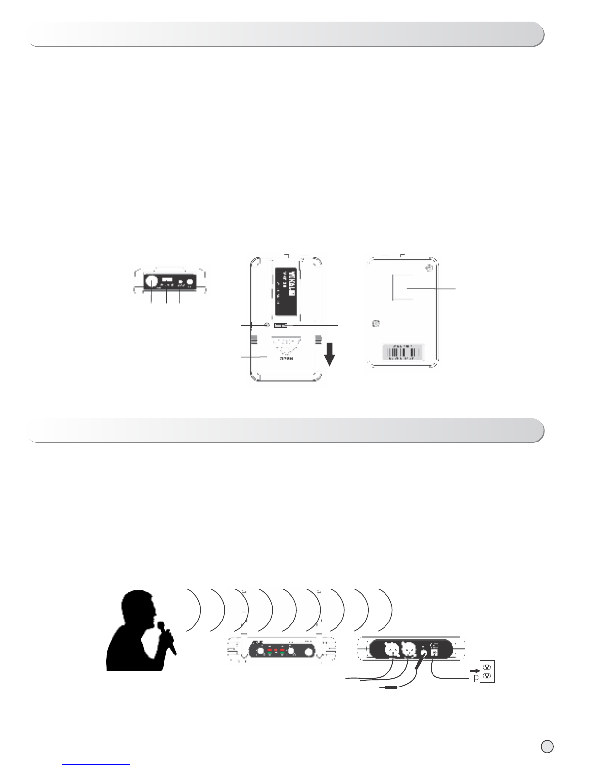
1 - POWER switch: turns unit ON and OFF
2 - POWER ON indicator: this red LED will turn ON when receiver is switched ON
3 - RF signal indicator: this green LED will turn ON when RF signal is received from the transmitter. For the
model VWR-25 there are indicators for channels A and B.
4 - Audio level indicator: shows the level of audio signal being received, turning ON when the level is satisfactory
5 - Volume Control: controls the output volume of the receiver
6 - Antennas for signal reception
7 - Balanced XLR audio output jacks
8 - Unbalanced ¼” audio output jack
9 - Power jack: connect to AC/DC power adapter
10 - AC/DC power adapter (110-220V): we recommend the use of the original power adapter only

3
6
10
2
2
4
4
3
3
VWR-25
VWR-15
1
1
5
5
7
7
8
8
9
9
6

HANDHELD TRANSMITTER FEATURES AND COMPONENTS
1 - Grille: protects capsule and reduces noises caused by breathing
2 - ON/OFF/MUTE key: when this key is put on the ON position, the LED (3) will turn on for a moment and
the microphone will be turned ON. On MUTE position, the system will stay ON but the audio capture will be
cut-off. On OFF position the system will be turned OFF.
3 - Low battery indicator: when this LED remains ON it indicates that the batteries must be replaced
4 - Battery compartment: requires use of 2 AA type batteries
5 - FM frequency used by the system
6 - Transmitter gain control
1
3
2
4
5
6
4

1 - Connect the power adapter to the DC input and to an AC power outlet
2 - Connect the balanced XLR or unbalanced ¼” output jack to the sound system, using the appropriate cable
depending on the option made
3 - Switch the transmitter ON/OFF key to the ON position. The transmitter LED indicator will turn on for a moment
and the receiver LED indicator will remain ON
4 - Adjust the volume on the receiver
5 - After use, turn receiver off and move the transmitter ON/OFF key to the OFF position to preserve battery
charge.
Note: when using the system in modes Lavalier and Headset, make sure the transmitter key is on
the correct position (“L” for Lavalier, “H” for headset).
OPERATING THE UHF SYSTEM
1 - ON/OFF/MUTE key: when this key is put on the ON position, the LED (3) will turn on for a moment and the
microphone will be turned ON. On MUTE position, the system will stay ON but the audio capture will be cut-off.
On OFF position the system will be turned OFF.
2 - Low battery indicator: when this LED remains ON it indicates that the batteries must be replaced
3 - Battery compartment: requires use of 2 AA type batteries. Move cover down to open.
4 - Input connector: for connection with the headset microphone, lavalier microphone or instrument cable
5 - Belt clip
6 - Audio gain control: adjusts the audio level according to the different types of signal input. Use a little flat
screwdriver to make the adjustment, turning clockwise to increase level, and anti-clockwise to decrease the
level
7 - Microphone selector key: “L” for Lavalier, “H” for headset
BODY-PACK TRANSMITTER FEATURES AND COMPONENTS
1
2
76
5
3
214
5

• RF Carrier Frequency Range: Approximately 460 to 970MHz (available frequencies depend on applicable
regulations in country system is used)
• Operation Range: 50m (aproximately 164ft) under typical conditions
• Audio Frequency Response: 100 to 18,000Hz, ±3dB
•THD: <1%
• Mobile status Range: >100dB
-29º to 74ºC (-20º to 165ºF) Note: Battery caracteristics may limit this range.
Power requirements
Nominal Current Drain
Modulation Type
RF Output
Max Deviation
Spurious Emission
Dimensions
1,5V AA battery x2
Less than 100mA
FM
More than 10 dBm
± 70 kHz
More than 55 dBm
238 x 50 x 50 mm (Hand Held)
100 x 65 x 30 mm (Body Pack)
BODY PACK / HAND HELD TRANSMITTER SPECIFICATIONS
Power Requirements (Adapter)
Power Requirements
Signal / Noise Ratio
Border Upon Channel Rejection
Image & Spurious Rejection
Audio Output Level
Receiving Sensitivity
Dimensions
120V or 230V AC, adaptor with 2.1mm female plug
13 ~ 15 DC nominal, 200mA / 300mA
More than 85 dB
More than 70 dB
More than 70 dB
0 ~ ± 300 mV
-105 dBm
170 x 100 x 90 mm
RECEIVER SPECIFICATIONS
SYSTEM SPECIFICATIONS
OPERATION TEMPERATURE RANGE
6

No sound.
No sound.
No sound.
No sound.
No sound.
Sound level different
from the instrument
Sound level differs
between different
guitars
Distortion level
increases gradually
Bursts of noise or
other audible radio
signals present
Momentary loss of
sound as transmitter
is moved around
Receiver power light
indicator is off
Receiver A/B signal
indicators are ON
Receiver A/B signal indicators
are OFF. Transmitter and
receiver power lights are ON
Receiver A/B signal indicators
are ON
Receiver A/B signal indicators
are ON
Receiver A/B light indicators
and transmitter low battery
indicator are ON
Receiver A/B signal indicators
are ON
Receiver A/B light indicators go
OFF when signal is lost
Switch transmitter POWER ON/OFF key to the
ON position. Make sure batteries are inserted
properly, observing battery (“+/-“). If batteries
are inserted properly, replace them with new ones.
Switch transmitter key to the ON position
Make sure the AC adapter is securely plugged
into the power outlet and into the DC input jack.
Make sure the AC power outlet supplies
proper voltage
Turn up the receiver volume control. Confirm
that the output connections from the receiver
to the external equipment are secure
Confirm that transmitter and receiver
frequencies match. Move transmitter closer
to receiver
Adjust transmitter gain level. Adjust receiver
volume if necessary.
Readjust transmitter gain level to compensate
for differences between guitar output levels
Replace transmitter battery
Identify potential sources of interference
(other RF sources) and/or use another wireless
system with a different UHF frequency
Reposition receiver and perform walk-through
test again. If audio dropout persists, mark the
“dead” spots and avoid the during performance
Transmitter red LED indicator
does not flash
Transmitter red LED
indicator flashes
TROBLESHOOTING
PROBLEM INDICATOR STATUS SOLUTION
7

MADE IN CHINA
This manual suits for next models
1
Table of contents
Other Vokal Microphone manuals