BUILDING REGULATIONS
This appliance must be installed and serviced
only by a competent person in accordance with
the current: IEE Regulations,
Building Regulation, Building Standards
(Scotland) (Consolidation), Building Regulations
(Northern Ireland), local water by-laws,
Health & Safety Document 63S (The Electricity at
Work Regulations 1989), IS 813 (Eire) and other
local requirements.
The relevant Standards should be followed,
including:
BS EN 15450: Heating systems in buildings –
Design of heat pump heating systems.
BS EN:12828 : Central heating for domestic
premises.
BS EN 7593 : Treatment of water in domestic hot
water central heating systems.
BS EN 14511 : Requirements heat pumps for
space heating and cooling.
BS EN 378 : Safety and environmental
requirements for heat pumps.
The Health and Safety at Work Act 1974.
The Management of Health and Safety at Work
Regulations 1999.
The Construction (Health, Safety and Welfare)
Regulations 1996.
The Construction (Design and Management)
Regulations 1994.
The Lifting Operations and Lifting Equipment
Regulations 1998.
Where no specific instruction is given, reference
should be made to the relevant codes of Practice.
There have been no banned substances
used in the manufacture of these
appliances.
________________________________________________________________
INDEX
1 GENERAL
.....................................................5
1.1 GENERAL PRECAUTIONS
....................................... 5
1.2 FUNDAMENTAL SAFETY RULES
............................ 5
1.3 DESCRIPTION OF THE APPLIANCE
....................... 6
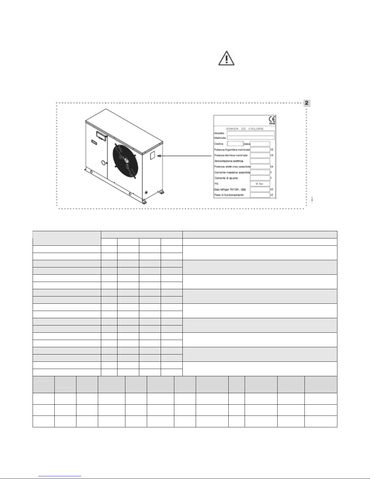
1.4 IDENTIFICATION
...................................................... 7
1.5 TECHNICAL DATA
................................................... 8
1.6 HYDRAULIC DATA
.................................................. 9
1.7 ACCESSORIES
....................................................... 9
1.7.1 Electric heater
............................................... 9
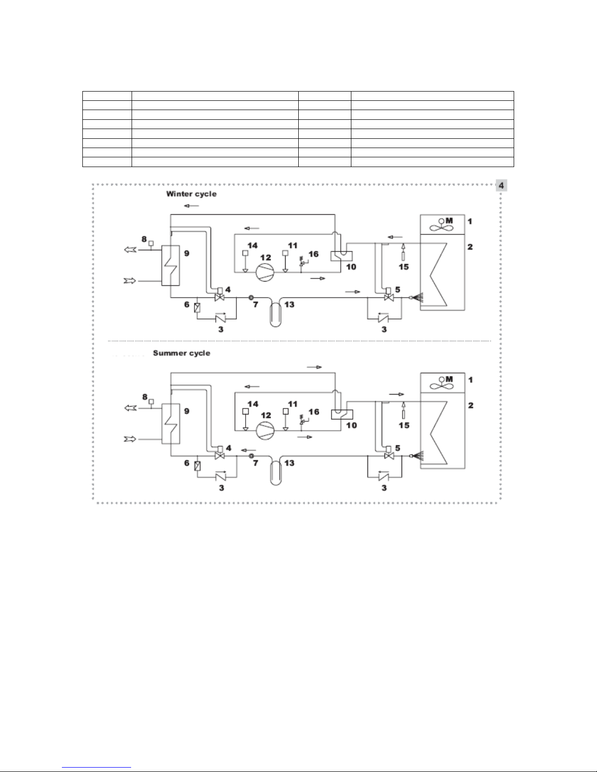
1.8 HEAT PUMP COOLING CIRCUIT
........................... 10
1.9 ELECTRICAL PANEL AND WIRING
DIAGRAM ...... 10
1.9.1 ARIA 6HP / 8HP Models ............ 10
1.9.2 ARIA 11HP Model ........................... 12
2 INSTALLER
................................................ 13
2.1 CONTROL PANEL
................................................... 13
2.2 ACTIVATION & DEACTIVATION
............................. 15
2.2.1 Heating / Cooling activation
......................... 15
2.2.2 Heating / Cooling deactivation
..................... 16
2.3 OPERATIONS PERFORMED WITH
THE REMOTE ON-OFF “SO” and
SUMMER-WINTER “SEI” SWITCHES
..................................................... 17
2.3.1 Cooling function
............................................ 17
2.3.2 Heating function
............................................ 17
2.4 SHUTDOWN FOR LONG PERIODS
....................... 17
2.5 CLEANING
.............................................................. 17
2.6 MAINTENANCE
....................................................... 17
2.7 USEFUL INFORMATION
......................................... 18
2.8 RECEIVING THE PRODUCT
.................................. 18
2.9 DIMENSIONS WITH PACKAGING
.......................... 18
2.10 DIMENSIONS WITHOUT PACKAGING
.................. 19