User Manual FKG-1 4 Operation Modes
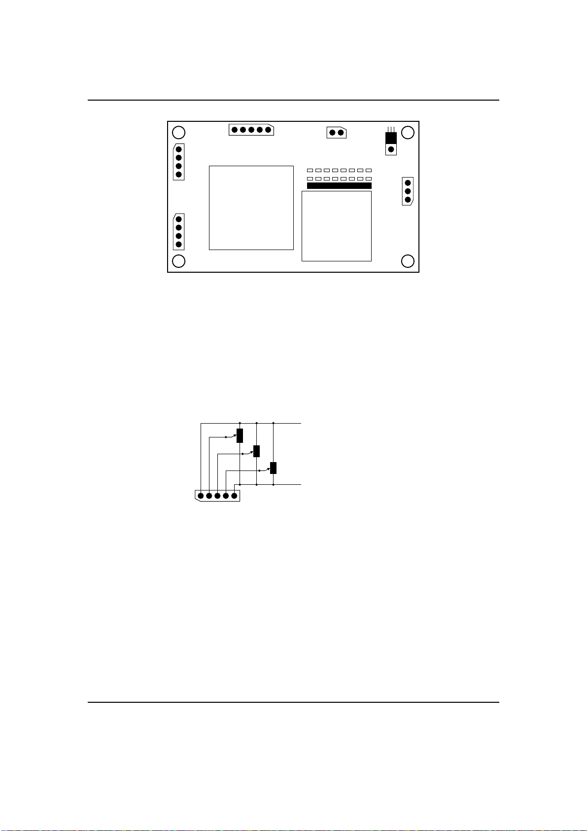
Table 4: Usage of the solder jumpers.
jumper default function
2,1 Off,On width of the vertical line as binary value.
3 Off toggle height between one (off) and two (on) pixels.
4 Off toggle baud rate between 9600bps (off) and 19200bps (on).
7 Off operation mode: potentiometer (off) or serial (on).
5,6,8 Off reserved.
Table 5: Configuration values of the line width
J2 J1 assignment
Off Off line width 1 pixel.
Off On line width 2 pixel.
On Off line width 3 pixel.
On On line width 4 pixel.
4 Operation Modes
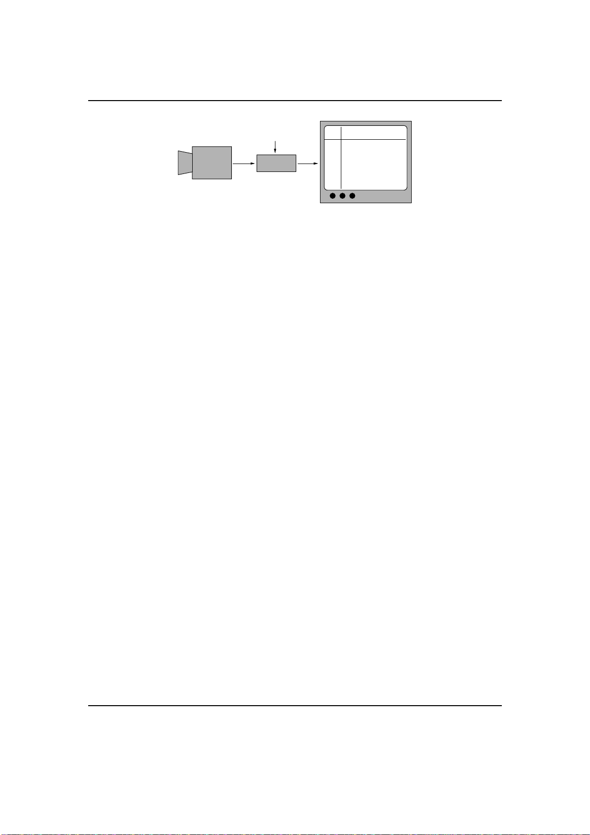
4.1 Controlled by Potentiometers
This operation mode is only active, if the solder jumper J7 is not shortened. If you select this
mode, the crosshair and the brightness is controlled by three potentiometers. The Potentiometer
P1 controls the horizontal position, while P2 controls the vertical position. With P3, the level of
the brightness is adjustable in 255 steps. The value of white is hereby 0 Ω!
It isn’t necessary to save any data in this operation mode. All settings are controlled by
potentiometers or solder jumpers.
4.2 Controlled by RS232
As an alternative to the previously mentioned potentiometer mode, the serial mode gives the
user full control over all functions of the device. The communication protocol3is the same for
all members of the FKG family. This allows the usage of a common graphical front-end called
FKG-GUI. This program is available for Microsoft Windows (TM). The latest release of the
program is always available at our Internet homepage (see cover page).
This operation mode is only active, if the solder jumper J7 is shortened!
3The serial protocol is a ASCII based character oriented protocol. The documentation for this protocol is only
available in German. For more information call our support team.
Revision 1.5, Dipl.-Ing. Joerg Desch / esw
8 / 16