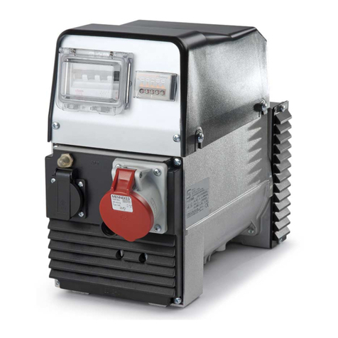
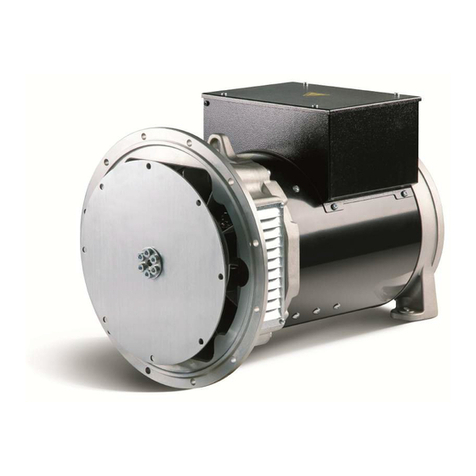
Soga PMG Series User manual

S
ERIE PMG
Manuale di uso e manutenzione
Use and Maintenance manual
187367
REV00
02/2021

2

3
INDICE
1 INFORMAZIONI SULLA SICUREZZA....................4
1.1 Fonti di possibile pericolo.........................................5
1.1.1 Pericoli meccanici.....................................................5
1.1.2 Pericoli elettrici..........................................................5
2 USO PREVISTO......................................................6
3 ISTRUZIONI PER L’INSTALLAZIONE,
L’IMPIEGO E LO STOCCAGGIO ...........................7
3.1 Informazioni generali................................................8
3.2 Movimentazione e sollevamento.............................8
3.3 Modalità di accoppiamento......................................9
3.4 Collegamenti e terminali...........................................9
3.5 Veri!ca della resistenza di isolamento ....................10
3.6 Messa in marcia .......................................................10
4 PRINCIPIO DI FUNZIONAMENTO ........................10
5 ASSISTENZA E MANUTENZIONE........................11
5.1 Smontaggio e rimontaggio..................................... 12
5.2 Cuscinetti ................................................................ 12
5.3 Risoluzione dei problemi........................................ 14
6 DEMOLIZIONE E SMALTIMENTO....................... 14
7 ALLEGATI............................................................... 16
COLLEGAMENTI IN MORSETTIERA.................. 17
ESPLOSO E PARTI DI RICAMBIO....................... 18
RICAMBI E ASSISTENZA..................................... 22
GARANZIA............................................................. 24
Dichiarazione di incorporazione ............................ 27
CONTENTS
1 SAFETY INFORMATION..........................................4
1.1 Sources of potential hazard......................................5
1.1.1 Mechanical hazard....................................................5
1.1.2 Electrical hazard........................................................5
2 USE............................................................................6
3 INSTRUCTIONS FOR INSTALLATION
AND STOCKING.......................................................7
3.1 General information...................................................8
3.2 Handling and lifting....................................................8
3.3 Coupling configurations ............................................9
3.4 Cabling and terminals ...............................................9
3.5 Insulation resistance check.......................................10
3.5 Initial start-up .............................................................10
4 OPERATING PRINCIPLE ........................................10
5 MAINTENANCE AND SERVICE .............................11
5.1 Disassembly and re-assembly............................... 12
5.2 Bearings.................................................................. 12
5.2 Troubleshooting...................................................... 15
6 DISMANTLING....................................................... 15
7 ANNEXES .............................................................. 16
TERMINAL BOARD CONNECTION .................... 17
EXPLODED VIEW AND SPARE PARTS LIST .... 18
SPARE PARTS & AFTERSALES.......................... 22
WARRANTY........................................................... 24
Declaration of Incorporation................................... 27

4
1 INFORMAZIONI SULLA SICUREZZA
Il “Manuale Uso e Manutenzione” accluso al generatore
fornisce importanti indicazioni riguardanti la sicurezza,
l’installazione, l’uso e la manutenzione.
Questo manuale di istruzioni è stato redatto sulla base
delle indicazioni fornite dalla Direttiva 2014/35/UE, nota
come “Direttiva Bassa Tensione” e dalla norma IEC
60204-1 (“Equipaggiamento elettrico delle macchine,
sicurezza del macchinario, principi di progettazione,
speci!che e principi tecnici”).
Attenersi scrupolosamente a quanto riportato nel ma-
nuale, che ha lo scopo di indicare le corrette condizioni
di installazione e manutenzione, al !ne di prevenire
eventuali malfunzionamenti del generatore ed evitare
situazioni di pericolo per l’utente. Questo prodotto è
stato progettato e costruito esclusivamente per l’utiliz-
zo indicato in questa documentazione. Usi non indicati
in questa documentazione potrebbero essere fonte di
danni al prodotto e fonte di pericolo. Sono stati ripor-
tati inoltre tutti i suggerimenti derivanti da esperienze
applicative, necessari per garantire l’uso corretto e si-
curo del generatore elettrico. Viene richiesto che i fon-
damentali lavori di predisposizione dell’impianto, mon-
taggio, installazione, messa in servizio, manutenzione,
vengano eseguiti da personale quali!cato e controllati
dal personale tecnico responsabile.
I generatori elettrici della serie PMG sono conformi alle
seguenti direttive:
- Direttiva europea 2014/35/UE (“Direttiva Bassa
tensione”);
- Direttiva europea 2014/30/UE (“Direttiva sulla
compatibilità elettromagnetica”);
- Direttiva europea 2011/65/UE (“Direttiva RoHS”);
I generatori della serie PMG sono stati progettati se-
guendo le seguenti norme internazionali IEC 60034
(“Macchine elettriche rotanti”).
In questo manuale vengono utilizzati alcuni simboli e con-
venzioni che hanno un signi!cato preciso.
ATTENZIONE!
Il simbolo si riferisce a situazioni di rischio
o a procedure pericolose che potrebbero
essere causa di danni al prodotto o di
lesioni alla persona.
AVVERTENZA!
Il simbolo segnala situazioni di rischio
o procedure pericolose che potrebbero
essere causa di gravi lesioni alla persona
o di decesso.
PERICOLO!
Il simbolo segnala situazioni di rischio o
procedure pericolose che causano gravi
lesioni alla persona o decesso.
1 SAFETY INFORMATION
The “User and Maintenance Manual” included with
the generator provides important indications regarding
safety, installation, use and maintenance.
This instruction manual has been compiled in accord-
ance with the dispositions supplied by the Directive
2014/35/EU (“Low Voltage Directive”) and by the IEC
60204-1 standard (“Electrical machine equipment, ma-
chinery safety, principles of design, specifications and
technical principles”).
Strictly observe the instructions given in the “User and
Maintenance Manual” that is provided to indicate the
correct conditions for installation, use and mainte-
nance, in order to prevent generator malfunctions and
avoid hazardous situations for the user. This product
has been designed and constructed solely for the ap-
plication indicated in this manual. Any use not specified
in this manual may cause damage to the product and
become a source of hazard.
Moreover, all the suggestions deriving from application
experience have been included, as these are neces-
sary to guarantee the correct, safe use of electric gen-
erators. It is requested that all the basic work of pre-
paring the plant, assembly, installation, start up and
maintenance be carried out by qualified staff and be
controlled by the technical staff responsible for it.
The PMG series generators comply with following di-
rectives:
-European Directive 2014/35/EU (“ Low Voltage Direc-
tive”);
-European Directive 2014/30/EU (“Electromagnetic
Compatibility Directive”);
-European Directive 2011/65/EU (“RoHS Directive”);
The PMG series generators were designed to meet the
following international standards: IEC 60034 (“Rotating
Electrical Machines”).
This manual uses various symbols and terms that have a
precise meaning. These are clearly defined below.
CAUTION!
This symbol signals risk conditions or
hazardous procedures that could cause
damage to the product or injury to
persons.
WARNING!
This symbol signals risk conditions or
hazardous procedures that could cause
severe injury or death.
DANGER!
This symbol signals risk conditions or
hazardous procedures that will cause
severe injury or death.

5
1.1 Fonti di possibile pericolo
Ci sono una varietà di fonti di potenziali pericoli che
possono causare la morte o gravi lesioni. Questi pe-
ricoli sono presenti durante l’installazione, il funziona-
mento, l’ ispezione o la manutenzione.
1.1.1 PERICOLI MECCANICI
ATTENZIONE!
Non toccare mai il rotore.
Mai cercare di fermare il rotore a mano.
Evitare che qualsiasi oggetto entri nel
rotore.
Mai cercare di fermare il rotore lancian-
do qualsiasi oggetto su di esso.
ATTENZIONE!
Indossare indumenti di sicurezza adeg-
uate e rendere l’area di lavoro il più pos-
sibile ordinata e sicura.
Utilizzare caschi di sicurezza, guanti, ecc.
Molta attenzione deve essere prestata alla resistenza ed
integrità del montaggio. Utilizzare mezzi idonei per il sol-
levamento e la movimentazione del generatore (Se pre-
senti, utilizzare tutti i golfari di sollevamento). La caduta
di oggetti è potenzialmente fatale. Non sottostare sotto i
carichi sospesi o sotto i montanti. Assicurarsi che gli asta-
nti siano tenuti al di fuori del raggio di caduta di eventuali
oggetti. Assicurarsi che eventuali oggetti o utensili sospesi
siano messi in sicurezza.
ATTENZIONE!
Fissare eventuali oggetti che potrebbero
cadere. Non sostare sotto carichi sosp-
esi e l’area di lavoro, indossare il casco
di sicurezza. Utilizzare solo sistemi di
montaggio adeguatamente progettati.
ATTENZIONE!
Gli anelli o golfari, di sollevamento
sono stati previsti per il sollevamento
del solo generatore. Una capacità di
sollevamento non adatta può causare
lesioni personali e gravi danni.
1.1.2 PERICOLI ELETTRICI
PERICOLO!
Non toccare i terminali dei "li, se il
generatore è in rotazione. Non toccare
i terminali dei "li, se il generatore non
è completamente scollegato dalla
linea / inverter.
PERICOLO!
Per il collegamento a massa fare riferi-
mento alle corrispondenti norme locali in
materia. Collegamenti a massa o di pro-
tezione eseguiti in modo errato possono
portare a lesioni o al decesso.
1.1 Sources of potential hazard
There are a variety of sources of potential hazards
which can result in death or serious injury. These dan-
gers exist during installation, operation, inspection or
maintenance.
1.1.1 MECHANICAL HAZARD
CAUTION!
Never touch the rotor in motion.
Never try to stop the rotor by hand.
Avoid any objects entering the rotor.
Never try to stop the rotor by throwing
any object into it.
CAUTION!
Wear appropriate safety equipment
and make the general working area as
a tidy and safe as possible.
Use safety helmets, gloves, etc.
Very careful attention must be given to the strength and
integrity of the mounting. Use appropriate tools to lift and
move the generator (For lifting use all eyebolts that the
generator is equipped with). Falling objects are potentially
fatal. Do not step underneath hanging loads or folding/
tilted masts. Make sure that onlookers are kept back be-
yond the collapse radius of any masts. Ensure that any
suspended objects or tools are secured.
CAUTION!
Secure any objects that might fall.
Do not go underneath hanging loads
and the working area; wear safety hel-
mets. Only use adequately designed
mounting systems.
CAUTION!
The eyebolts have been designed for
the lifting of the generator only. An
insuf!cient loadbearing capacity can
cause severe injury and damage.
1.1.2 ELECTRICAL HAZARD
DANGER!
Don’t touch the wire terminals if the
generator is rotating.
Don’t touch the wire terminals if
the generator is not completely
disconnected to the line/inverter.
DANGER!
Follow local regulations on earthing
for the ground connection. An
inef!cient earth connection can
cause injury or death.

6
ATTENZIONE!
Le connessioni elettriche devono
essere eseguite da personale
quali"cato. Connessioni eseguite
in modo errato possono causare
danni a persone e danneggiare il
generatore.
2 USO PREVISTO
I generatori elettrici della serie PMG con altezza d’asse
compresa tra 90 e 160 sono destinati ad installazioni di
tipo industriale e commerciale. Sono generatori sincro-
ni trifase a magneti permanenti del tipo chiuso. La scel-
ta dei materiali e del tipo di impregnazione permettono
l’uso di questi generatori in climi tropicali.
Sulla targhetta sono riportati i seguenti dati: potenza,
tensione, frequenza, corrente e velocità nominali. Se
non diversamente speci!cato, i modelli sono progetta-
ti per temperature ambientali comprese tra –15°C e +
40°C e per altitudini non superiori a 1000m s.l.m..
I generatori, se non diversamente speci!cato, sono
protetti secondo il grado IP54 della norma IEC 60034-
5.
Su richiesta si eseguono trattamenti speciali per am-
bienti particolarmente corrosivi e ad elevata umidità.
Per temperature maggiori di 40°C e per ambienti con
CAUTION!
Only quali•ed personel can make
the electrical connections. Wrong
connections can cause injury to
the persons and can damage the
generator.
2 USE
The electric generators of the PMG series, with an axial
height range from 90 to 160, are intended for industrial
and commercial installation. They are three-phase syn-
chronous permanent magnets closed type generators.
The choice of materials and the type of impregnation
enable these motors to be used in tropical climates.
On the nameplate are shown the following data: nomi-
nal power, voltage, frequency, current and speed.
Unless otherwise specified, models are designed for
ambient temperatures between -15°C to + 40°C and
altitudes up to 1000 m.a.s.l..
If not otherwise specified, the generators are supplied
with IP54 protection class, according to IEC 60034-5
standard.
Special treatments for particular corrosive environ-
ments and those with high humidity are available on
request.
TIPO ALTERNATORE/ ALTERNATOR TYPE
CODICE ALTERNATORE/ ALTERNATOR CODE
N° SERIALE / SERIAL NUMBER
Fig. 1.1

7
temperature costantemente inferiori ai -15°C è consi-
gliabile consultare di volta in volta i nostri Uf•ci Tecnici.
Per sovraccarichi, servizi di durata limitata o per servizi
intermittenti con frequenti avviamenti occorre interpel-
lare il nostro Uf•cio Tecnico fornendo le informazioni
riguardo il tipo di servizio, il numero degli avviamenti
orari.
Per aumentare la sicurezza di funzionamento in pre-
senza di servizi particolarmente gravosi, si possono
installare negli avvolgimenti dei particolari sensori ter-
mici.
3 ISTRUZIONI PER L’INSTALLAZIONE,
L’IMPIEGO E LO STOCCAGGIO
Tutti i lavori di installazione, montaggio, messa in ser-
vizio, manutenzione, devono essere eseguiti da per-
sonale quali•cato e controllati dal personale tecnico
responsabile.
Il generatore elettrico è un componente che viene
meccanicamente accoppiato ad un’altra macchina sin-
gola o costituente parte di un impianto ed è pertanto
responsabilità di chi esegue l’installazione garantire la
conformità a tutte le prescrizioni e le raccomandazioni
delle norme IEC 60204-1 sull’equipaggiamento elettri-
co delle macchine e al grado di sicurezza stabilito dalla
Direttiva CE.
Il generatore esce dalla fabbrica pronto per l’installa-
zione dopo accurati controlli di qualità durante il ciclo
di produzione e al collaudo •nale per accertarne la
rispondenza alle speci•che di progetto. Al momento
della ricezione si raccomanda di esaminare il genera-
tore per veri•care che non abbia subito danni durante
il trasporto o vi siano particolari mancanti. Se il genera-
tore non viene posto immediatamente in servizio dovrà
essere immagazzinato in luogo coperto, pulito e privo
di umidità. Installare il generatore in modo da prevede-
re la possibilità di ispezioni e manutenzioni durante il
funzionamento, in ambiente aerato, lontano da fonti di
calore. Evitare che la vicinanza di ostacoli impedisca
la ventilazione e che l’aria calda in uscita sia di nuovo
aspirata.
L’eventuale basamento del generatore deve essere
piano, robusto in modo d’assorbire le vibrazioni, suf•-
cientemente rigido da mantenere l’allineamento.
Il generatore deve essere sempre ben installato, so-
prattutto se accoppiato direttamente alla macchina
condotta. In caso di vibrazioni eccessive o guasti dei
cuscinetti controllare immediatamente l’allineamento
che potrebbe risultare disassato. La trasmissione di po-
tenza dalla macchina conduttrice può avvenire tramite
accoppiamento diretto, cinghie di trasmissione, ingra-
naggi, etc. Nel caso di accoppiamento diretto si deve
usare un giunto elastico o un giunto flessibile che eviti
la trasmissione di eventuali spinte assiali ai cuscinetti.
Nel caso di accoppiamento con cinghie di trasmissione,
installare il generatore con l’albero parallelo a quello
della macchina conduttrice e su di un tendicinghia per
For temperatures over 40°C and for environments with
temperatures constantly below -15°C, it is advisable to
contact our Technical Office. For overloads, services
of limited duration or for intermittent duty with frequent
start-ups it is necessary to contact us and give the in-
formation on the type of duty, the number of start-ups
every hour.
Special thermal sensors can be installed in the wind-
ings for a higher operational safety with particularly
heavy duty.
3 INSTRUCTIONS FOR INSTALLATION
AND STOCKING
All works of installation, assembly, commissioning,
maintenance must be carried out by qualified person-
nel only and checked by the technical responsible for it.
The electric generator is a component which is me-
chanically connected to another single machine or it is
part of a plant and it is, therefore, responsibility of the
installer to guarantee compliance with all the prescrip-
tions and recommendations of the IEC 60204-1 regu-
lations regarding the electrical equipment of machines
and the degree of safety established by machine Direc-
tive.
Generator leaves the factory ready for installation after
accurate quality controls during the production cycle
and final testing to verify compliance with the project
specifications.
On receipt of the machine we recommend inspecting
the generator to check that it has not been damaged
during transportation or that there are no parts missing.
If the generator is not put into service at once it should
be stored in a covered, clean and dry place.
Provide the possibility of inspection and maintenance
during its operation.
Install the generator in an aerated room, far from heat-
ing sources.
Make sure that near obstacles do not avert ventilation
and that hot air coming out is sucked again.
If the generator is installed on a basement, it should
be flat, strong enough to absorb vibrations and rigid
enough to maintain alignment.
The generator should always be well installed, above
all if coupled directly with the driven machine.
In case of excessive vibrations or damage of the bear-
ings, check the alignment at once as the generator
could be misaligned.
Power transmission from the driving machine can be
done by direct coupling, transmission belts, gears, etc.
In case of direct connection, an elastic coupling or a
flexible coupling should be used to avoid the transmis-
sion of any axial thrusts to the bearings.
In case of coupling by transmission belts, install the
generator with the shaft parallel to that of the driving
machine and on a belt tightening pulley to adjust belt
tension.

8
poter regolare la tensione delle cinghie. Tenere ben
presente che una tensione eccessiva è nociva alla du-
rata dei cuscinetti e, nei casi più gravi, può provocare
la rottura dell’albero.
IMPORTANTE!
Non superare mai i carichi assiali e
radiali massimi consentiti e in caso
di dubbi interpellare il nostro Uf"cio
Tecnico (vedi tabelle 7.1 e 7.2).
Salvo diversa indicazione, il rotore è equilibrato dina-
micamente con mezza linguetta. Anche gli organi di
trasmissione devono essere accuratamente bilancia-
ti prima del montaggio. Il montaggio e lo smontaggio
degli organi di accoppiamento e dei cuscinetti devono
essere eseguiti da personale quali!cato con modalità e
attrezzi adatti allo scopo.
3.1 Informazioni generali
In caso di rumori o vibrazioni anomale controllare l’ac-
coppiamento con la macchina !nale. È compito del pro-
gettista !nale, utilizzare gli accorgimenti necessari per
curare l’accoppiamento e il supporto al !ne di evitare
rumori, vibrazioni, guasti e usure anomale dei cusci-
netti.
In caso di dubbi interpellare il nostro Uf!cio Tecnico.
ATTENZIONE!
Il montaggio e lo smontaggio del
generatore deve essere eseguito da
personale quali"cato e secondo mo-
dalità ed attrezzi adatti allo scopo.
3.2 Movimentazione e giacenza a
magazzino
Sollevare e movimentare il generatore con mezzi ido-
nei supportandolo con pallet o sostenendolo mediante
anelli di sollevamento. Il peso del generatore lo si può
leggere nei dati di targa.
ATTENZIONE!
Gli anelli o golfari, di sollevamento
sono stati previsti per il sollevamen-
to del solo generatore. Una capacità
di sollevamento non adatta può cau-
sare lesioni personali e gravi danni.
Se il generatore non viene posto immediatamente in
servizio, dovrà essere immagazzinato in un luogo co-
perto, pulito, asciutto e privo di vibrazioni.
Dopo quattro anni dalla fornitura e con un immagazzi-
namento in condizioni favorevoli è consigliabile sostitu-
ire i cuscinetti e controllare che la resistenza di isola-
mento sia superiore a 10 MΩ. In condizioni sfavorevoli
tale tempo si dimezza.
Keep in mind that the excessive tension is harmful to
bearings life and, in the worst case, could cause the
breaking of the shaft.
IMPORTANT!
Never exceed the maximum axial and
radial loads allowed and, when in
doubt, consult our Technical Of•ce.
(See tables 7.1 and 7.2).
Unless otherwise specified, the rotor is balanced dy-
namically by half a key; also the transmission organs
should be carefully balanced before assembly. Assem-
bly and disassembly of the coupling organs and the
bearings should be carried out by qualified personnel
only and using adequate tools.
3.1 General information
In the case of noise or abnormal vibrations check the
coupling with the whole machine. Therefore the plant
engineer must take all necessary measures to ensure
the correct coupling and supports in order to prevent
noise, vibrations, faults and abnormal wear of the bear-
ings. Contact our technical department to resolve prob-
lems incurred.
CAUTION!
Assembling and disassembling pro-
cedures must be carried out solely by
quali•ed personnel by means and tools
suitable for the purpose.
3.2 Handling, lifting and storage
Lift and handle the generator with suitable equipment
either on a pallet or by eyebolts. The generator weight
is shown on the nameplate.
CAUTION!
Eyebolts have been designed for the
lifting of the generator only. An insuf-
•cient loadbearing capacity can cause
severe injury and damage.
If the generator is not immediately commissioned, it
should be stored in a sheltered, clean and dry place,
free of vibrations.
After four years from the date of supply, and with the
motor stored in good conditions, it is advisable to re-
place the bearings and check if the insulation resist-
ance is higher than 10 MΩ. Under unfavourable stor-
age conditions, this check-time is reduced by half.

9
3.3 Fori scarico condensa
Se il generatore è provvisto di foro scarico condensa
chiuso da un tappo a vite, procedere periodicamente
allo scarico della condensa (da effettuarsi con gene-
ratore spento). In certe condizioni, e comunque non in
zone di pericolo, può essere opportuno eliminare gli
eventuali tappi di chiusura. Il grado di protezione del
generatore senza tappi di chiusura risulta diminuito.
Taluni generatori di produzione SOGAENERGIES han-
no un tappo sullo scarico condensa di colore verde.
Tale tappo ha delle fessure capillari che permettono la
fuoriuscita della condensa senza diminuirne il grado di
protezione. Anche in questo caso si consiglia comun-
que di togliere periodicamente il tappo e pulirlo con
dell’aria compressa onde evitare che particelle di spor-
co chiudano i condotti capillari di scarico.
3.4 Collegamenti e terminali
I generatori vengono forniti con 6 cavi uscenti ai quali
corrispondono le fasi U-V-W.
Facendo girare il generatore in senso orario (visto lato
opposto cavi) le tensioni rispettano la sequenza di fase
U-L1, V-L2, W-L3.
Il collegamento elettrico va eseguito a macchina fer-
ma, rispettando scrupolosamente le norme di sicurezza
precisate nella norma IEC 60204-1.
PERICOLO!
Per il collegamento a massa fare ri-
ferimento alle corrispondenti norme
locali in materia. Collegamenti a mas-
sa o di protezione eseguiti in modo
errato possono portare a lesioni o al
decesso.
Le super!ci di contatto devono essere pulite e protette
dalla corrosione. Collegare il conduttore di messa a ter-
ra sul morsetto con il simbolo:
Il quadro elettrico della macchina avente il generatore
PMG come componente, deve essere messo a massa
secondo le normative vigenti nel paese in cui la mac-
china stessa viene prodotta.
IMPORTANTE!
Impiegare cavi di alimentazione
aventi sezione adeguata a sopporta-
re la corrente erogata dal generatore
evitando sovrariscaldamenti e cadu-
te di tensione eccessive.
Impedire che i cavi trasmettano sollecitazioni mecca-
niche ai morsetti del generatore. Al termine di tutte le
connessioni, assicurarsi che pressacavi e coprimorset-
tiera siano ben chiusi per garantire il massimo grado
di protezione.
3.3 Condensate drain holes
If the generator is provided with condensate drain ports
closed with a screw cap, periodically drain the con-
densate (this operation has to be carried out with the
generator at standstill). In certain conditions, but not in
danger areas, it might be suitable to remove the clos-
ing caps. The protection level of the generator without
closing caps is reduced.
Some generators manufactured by SOGAENERGIES
are provided with a green condensate drain cap. This
cap has capillary slots which allow the exit of conden-
sate without reducing the protection level. Even in this
case, it is recommended to remove periodically the cap
and clean it with compressed air so as to avoid that dirt
clogs the drain capillary ducts.
3.4 Cabling and terminals
Generators are equipped with 6 outgoing leads that
corresponds to the U-V-W phase.
By turning the generator clockwise (seen from the op-
posite side of the leads), voltages are in the phase se-
quence L1-U, L2-V, L3-W.
Electrical wiring has to be carried out when the ma-
chine is still, respecting scrupulously the safety warn-
ings given in the IEC 60204-1 standard.
DANGER!
Follow local regulations on earthing for
the ground connection. An inef!cient
earth connection can cause injury or
death.
Contact surfaces should be clean and protected against
corrosione. Earthing is to be carried out to the terminal
with the corresponding symbol:
The earthing of the electrical panel, in machines that
use PMG generator as a component, must be carried
out in accordance with local (national) regulations in
use.
IMPORTANT!
Use power supply cables which have
an adequate cross-section to bear the
current of the generator thus avoiding
overheating and/or power failure.
Prevent the cables from transmitting mechanical stress
to the motor terminals and, having carried out all con-
nections, make sure that the cable glands and the ter-
minal box cover are well closed so as to have maximum
protection.

10
3.5 Veri•ca della resistenza di
isolamento
Prima della messa in servizio veri!care che la resisten-
za d’isolamento non sia inferiore a 10 MΩ. Per macchi-
ne che hanno già lavorato per lunghi periodi di tempo si
deve veri!care che la resistenza d’isolamento dell’av-
volgimento non sia inferiore a 1 MΩ(i valori sono riferiti
ad una temperatura ambiente di 25°C applicando una
tensione continua di 500 V).
Se vengono rilevati valori inferiori, l’avvolgimento pre-
senta una eccessiva e pericolosa umidità per cui è ne-
cessario essiccarlo ad una temperatura di 60 - 70°C,
ricorrendo ad una ditta specializzata. Eseguire l’essic-
cazione del solo avvolgimento.
3.6 Messa in marcia
Prima della messa in servizio veri!care l’allineamento
con gli organi accoppiati, le connessioni e il collega-
mento per la messa a terra. Veri!care che siano state
chiuse le protezioni degli organi in movimento, che l’in-
gresso dell’aria sia libero e che l’albero ruoti liberamen-
te. Eseguire dunque una prova funzionale per veri!care
la rotazione. All’atto della messa in funzione porre at-
tenzione ad eventuali rumori anomali che potrebbero
indicare un allineamento non corretto del generatore.
Se il motore è stato immagazzinato per un periodo che
supera i 3 anni è consigliabile cambiare il grasso dei
cuscinetti o sostituirli se del tipo auto lubri!cato.
ATTENZIONE!
Non toccare il generatore durante il
funzionamento e subito dopo l’arre-
sto del gruppo, in quanto potrebbero
esservi delle super•ci a temperatura
elevata.
AVVERTENZA!
Dopo aver messo in servizio il gene-
ratore accertarsi che non superi la
potenza nominale in targa. Non so-
vraccaricare il generatore anche se
per tempi brevi.
4 PRINCIPIO DI FUNZIONAMENTO
I generatori della serie PMG sono generatori sincroni a
magneti permanenti. L’eccitazione è garantita dai ma-
gneti permanenti e quindi la macchina non necessita
dell’avvolgimento di eccitazione sul rotore. La struttura
del generatore risulta così più semplice e robusta. La
tensione a vuoto generata dalla macchina è quindi pro-
porzionale alla velocità di rotazione.
I generatori sincroni a magneti permanenti non hanno
un sistema di regolazione della tensione di uscita. Ne
risulta che la tensione a carico è leggermente inferiore
rispetto la tensione a vuoto (Consultare la scheda tec-
nica per maggiori informazioni). In targa è indicata la
tensione a carico.
3.5 Insulation resistance check
At first commissioning, check that the insulation resist-
ance is not lower than 10 MΩ. The insulation resistance
of windings that have operated for long period of time
should be over 1 MΩ(the values refer to a room tem-
perature of 25°C and a dc voltage of 500V).
Lower values indicate that the winding has excessive,
dangerous humidity and so it should be dried at 60 -
70°C by a specialised company. Dry only the stator
winding.
3.6 Initial start-up
Before commissioning, check the correct alignment of
the coupled elements, as well as the correct connec-
tions and earthing. Make sure the protections of live
components are closed, that the air inlet is free from
obstructions and the shaft turns smoothly.
Perform an operating test to check rotation. During the
initial start-up, pay particular attention for any unusual
noises that might signal an incorrect alignment of the
generator. If the motor has been stored for a period
longer than 3 years, it is advisable to change the bear-
ing grease or replace the bearings if they are self-lubri-
cating type.
CAUTION!
Do not touch the generator while in
operation and straight after the gener-
ating set has stopped because certain
parts may still be very hot.
WARNING!
After the initial start-up of the genera-
tor, make sure that the power does not
exceed the rated one on the nameplate.
Do not overload the generator, even for
a short period of time.
4 OPERATING PRINCIPLE
The generators of the PMG series are synchronous
generators with permanent magnets. The excitation
is provided by permanent magnets and therefore the
machine does not require excitation of the winding on
the rotor. The structure of the generator is thus more
simple and robust. The open circuit voltage genera-
ted by the machine is then proportional to the speed
of rotation (View the data sheet for more information).
Synchronous generators with permanent magnets do
not have a regulating system for the output voltage.
As a result, the load voltage is slightly lower than the
open circuit voltage (Refer to the data sheet for more
information). On the nameplate is written the voltage at
load operation.

11
5 ASSISTENZA E MANUTENZIONE
AVVERTENZA!
Qualsiasi intervento sul generatore
deve essere effettuato a macchi-
na ferma e scollegata dalla rete di
alimentazione. (Compresi i circuiti
ausiliari come le resistenze anticon-
densa).
AVVERTENZA!
Non utilizzare in alcuna occasione
liquidi o acqua. Non pulire con aria
compressa le parti elettriche interne
perchè potrebbero veri"carsi corto-
circuiti o altre anomalie.
AVVERTENZA!
Non toccare il generatore durante il
funzionamento e subito dopo l’arre-
sto del gruppo in quanto vi potreb-
bero essere super"ci a temperatura
elevata.
Le macchine elettriche rotanti pre-
sentano parti pericolose in quanto
poste sotto tensione e con parti in
movimento durante il funzionamen-
to. Pertanto possono causare gravi
danni a persone o cose:
- un uso improprio
- la rimozione delle protezioni e lo
scollegamento dei dispositivi di
protezione
- la carenza di ispezioni e manu-
tenzione.
È buona regola veri!care periodicamente che il gene-
ratore funzioni senza vibrazioni o rumori anomali, che
l’erogazione di corrente non superi quello indicato in
targa, che l’ingresso dell’aria dal copriventola non sia
impedito, che sul generatore non siano presenti tracce
di polvere, olio o altre impurità, che i conduttori elettrici
siano ben !ssati alla morsettiera e non presentino se-
gni di deterioramento, che l’accoppiamento sia in per-
fette condizioni e non superi i valori di carico assiale/
radiale ammessi.
Ogni irregolarità rilevata dovrà essere prontamente
corretta.
Le manutenzioni sopra descritte non presuppongono
lo smontaggio del generatore. Questo però si rende
necessario se bisogna sostituire i cuscinetti. In tale oc-
casione si dovranno veri!care tutti i serraggi di viti e
bulloni secondo la tabella 7.3, la resistenza d’isolamen-
to e l’allineamento alla macchina accoppiata.
5 MAINTENANCE AND SERVICE
WARNING!
Any operation to the motor must be
carried out with machine at standstill
and disconnected from the power grid.
(Included the auxiliary circuits such as
anti-condensation resistances).
WARNING!
Never and for no reason whatsoever
use fluids or water. Do not use com-
pressed air to clean internal electrical
parts since this could cause short cir-
cuits or similar failures.
WARNING!
Never touch the generator during op-
eration or immediately after stopping
it because some surfaces might still
be very hot. Electric rotating machines
have dangerous parts. When operating
they are under voltage and have rotat-
ing components. Therefore:
- the improper use
- the removal of protective covers
and the disconnection of protec-
tion devices
- the inadequate inspection and
maintenance.
can cause personal injury or property
damage.
It is a good rule to check periodically if the generator
is operating without vibrations or strange noises, if the
current generated does not exceed the nominal one
indicated in the nameplate, if the inlet air from the fan
cover is not obstructed and that there are no traces of
dust, oil or other impurities on the generator, if power
terminals are well connected to the terminal board and
no wear signs are visible, if the coupling is in good
condition and does not exceed the maximum axial and
radial load values permitted. Any irregularity detected
must be promptly corrected.
The above maintenance operations do not require the
generator disassembly. But, if bearing have to be re-
placed, disassembly is necessary. On this occasion
tightness of all screws and bolts should be checked
according to table 7.3. Insulation resistance and align-
ment to the coupled machine should also be checked.

12
5.1 Smontaggio e rimontaggio
AVVERTENZA!
Eseguire qualsiasi lavoro sulla mac-
china solo in assenza di tensione.
Il montaggio e lo smontaggio degli
organi di accoppiamento e dei cu-
scinetti devono venire effettuati da
personale quali"cato con modalità
ed attrezzi adatti allo scopo.
L’eventuale smontaggio del generatore si esegue libe-
rando il generatore dagli organi di accoppiamento con
la macchina operatrice.
Togliere, successivamente il copriventola e la ventola
asportando le relative parti di !ssaggio. Rimuovere la
linguetta, e togliere i tiranti che bloccano lo scudo/"an-
gia anteriore. Agire con due leve sulle orecchie dello
scudo/"angia anteriore e spostarlo dalla cassa.
S!lare il rotore e lo scudo/"angia anteriore prestando
particolare attenzione a non danneggiare l’avvolgimen-
to.
Per l’estrazione dei cuscinetti adoperare un estratto-
re. Per facilitare l’assemblaggio dei nuovi cuscinetti è
buona norma usare un tubo di ottone o di rame con
super!cie di appoggio corrispondente all’anello interno
degli stessi; sono da evitare colpi e martellate per non
danneggiarli.
Il montaggio si effettua con sequenza inversa da quella
indicata per lo smontaggio. In occasione della sostitu-
zione dei cuscinetti, si consiglia di pulire i supporti e so-
stituire eventuali elementi di tenuta soggetti ad usura.
Dovendo sostituire qualche elemento di !ssaggio, as-
sicurarsi che questo sia dello stesso tipo e classe di
resistenza di quello originale.
Nell’eseguire il montaggio, assicurarsi che le coppie di
serraggio di viti e bulloni siano conformi ai valori ripor-
tati in tabella 7.3.
AVVERTENZA!
Nei generatori con forma costruttiva
B14 assicurarsi di non usare viti di
"ssaggio troppo lunghe. Questo per
evitare il rischio di eventuali pericoli
elettrici. Assicurarsi inoltre di sigilla-
re adeguatamente i fori non utilizzati
della #angia.
5.2 Cuscinetti
Le macchine in esecuzione standard hanno cuscinet-
ti a doppio schermo autolubri!canti e non richiedono
manutenzione.
Una volta usurati, i cuscinetti vanno sostituiti. In tale
occasione pulire i supporti e veri!care che non siano
presenti usure sui mozzi degli scudi/"angie.
Il tipo di cuscinetti utilizzati in ciascun motore è riporta-
tato in tabella 7.4.
5.1 Disassembly and re-assembly
WARNING!
Any operation to the generator must be
carried out with machine at standstill.
The assembly and disassembly of the
coupling elements and the bearings
must be carried out by quali!ed per-
sonnel with methods and tools suitable
for the purpose.
Any disassembly of the generator should be carried out
by disconnecting the coupling elements from the drive
machine.
At this point, remove the fan cover and the fan, taking
away the relevant fastening parts.
Remove the key, take off the tie rods fastening the D.E.
shield/flange.
Act with two levers on the ears of the D.E. shield/flange
and remove it from the housing.
Take off the rotor and the D.E. shield or flange taking
special care not to damage the winding.
Use an extractor to remove the bearings. To facilitate
the assembly of the new bearings it is good rule to use
a brass or copper tube with a resting surface corre-
sponding to the inner ring of the bearings.
Avoid knocking or hammering so as not to damage
them.
To assemble the generator follow the instructions in re-
verse order. During the replacement of the bearings, it
is recommended to clean the housings and replace any
sealing element subject to wear.
For new fastening components make sure that they are
of the same type and resistance class of the original
element.
When assembling the generator make sure that the
fastening couples of screws and bolts comply with ta-
ble 7.3.
WARNING!
For B14 mounting type generators be
sure not to use screws too long.
This to avoid electrical hazards.
Be sure also to properly seal the ho-
les on the #ange which are not used.
5.2 Bearings
Standard machines are provided with self-lubricating,
double shield bearings and do not require any main-
tenance.
Once worn, bearings must be replaced. When replac-
ing the bearings, clean the bearing housing and check
that no abrasion is visible on the hubs of the shields/
flanges.
In table 7.4 are indicated the bearing type used for
every motor size.

13

14
5.3 Risoluzione dei problemi
INCONVENIENTI CAUSE COSA FARE
La tensione del
generatore a vuoto è
troppo alta/bassa.
1) Velocità troppo elevata/
bassa.
2) temperatura troppo bassa/
alta.
1) Controllare velocità e frequenza.
2) Controllare che la temperatura ambiente rientri
all’interno del campo speci!cato in targa.
La tensione del
generatore è corretta
a vuoto ma troppo
bassa a carico.
1) Possibile sovraccarico.
2) Power factor <1.
1) Veri!care che la corrente erogata non sia
superiore a quella in targa ed eventualmente
ridurre il carico. Controllare i parametri impostati
nell’inverter.
La tensione del
generatore è instabile.
1) Contatti incerti.
2) Velocità del generatore
instabile.
3) Carico variabile.
1) Controllare le connessioni.
2) Veri!care se la velocità è costante. Regolare la
velocità del generatore agendo sul motore primo.
3) Controllare la stabilità del carico.
Sovratemperature
elevate negli
avvolgimenti.
1) Possibile sovraccarico.
2) Scarso raffreddamento
1) Veri!care che la corrente erogata non sia
superiore a quella in targa ed eventualmente
ridurre il carico. Controllare i parametri impostati
nell’inverter.
2) Controllare il circuito di ventilazione.
Macchina rumorosa. 1) Cuscinetti sovraccaricati.
2) Accoppiamento realizzato in
modo sbagliato.
3) Il generatore sta lavorando
al di sopra delle sue
prestazioni nominali.
4) Parametri errati impostati
nell’inverter.
1) Controllare i carichi assiali e radiali.
2) Veri!care e correggere l’accoppiamento.
3) Ridurre il carico.
4) Controllare e modi!care i valori dei parametri.
Tab. 5.1
6 DEMOLIZIONE E SMALTIMENTO
L’alternatore è costituito in massima parte da acciaio,
ghisa e rame. L’eliminazione dei materiali va fatta nel
rispetto delle norme vigenti. Nel caso di demolizione
del generatore porre attenzione ai magneti permanenti
posizionati sul rotore. E’ opportuno in caso di recupero
materiali, che vengano separati per tipologia (acciaio,
rame, alluminio, plastica, etc.). Rivolgersi ad un’agen-
zia di smaltimento. Assicurarsi che nessuna parte del
generatore venga dispersa nell’ambiente.
PERICOLO!
Persone con peacemaker e/o altri di-
spositivi elettronici biomedicali non
possono eseguire lo smontaggio del
generatore.

15
5.3 Troubleshooting
PROBLEM CAUSES WHAT TO DO
The voltage at no load is
too high/low
1) The speed is too high/low
2) Temperature too low/high.
1) Check speed/frequency.
2) Check if the ambient temperature is inside the
range specified in the nameplate.
The generator voltage at
no load is correct but too
low when connecting the
load (stand-alone mode).
1) Possible overload.
2) Power factor <1.
1) Make sure the generated current is not higher
than the rated one and possibly reduce the load.
Check the inverter parameters set-up.
The generator voltage is
unstable.
1) Poor contacts.
2) Unstable generator speed.
3) Unstable load/inverter.
1) Check contacts.
2) Check if the speed is constant. Regulate the
speed of the generator acting on the prime mover.
3) Check the load/inverter.
The temperature rise in
the winding is too high.
1) Possible overload.
2) Poor cooling
1) Make sure the generated current is not higher
than the rated one and possibly reduce the load.
Check the inverter parameters set-up.
2) Check the cooling system.
Machine noisy. 1) Over loaded bearings.
2) Faulty coupling.
3) The generator is
working above its rated
performances.
4) Wrong parameters set in
the inverter.
1) Check axial and radial loads.
2) Check and fix the coupling.
3) Reduce the load.
4) Check and change the inverter parameters.
Tab. 5.2
6 DISMANTLING
Most of generator parts are made of steel, cast iron
and copper. All materials should be eliminated in com-
pliance with the local dispositions. When dismantling
the generator pay attention to the permanent magnet
in the rotor. To aid recovery of the material, it is best to
classify it by type (I.e. steel, copper, aluminium, plastic,
etc.). When dismantling the machine, contact an au-
thorised scrap dealer and ensure that no parts of the
generator are dumped in the environment.
DANGER!
The disassembly of the generator
must NOT be carried out by people
with pacemakers or any other im-
planted medical electronic device.

16
7 ALLEGATI 7 ANNEXES
MASSIMO CARICO RADIALE AMMISSIBILE - MAXIMUM RADIAL LOAD
Grandezza IEC
IEC size
Carico radiale massimo (tiro cinghia) —Misura espressa in kN
Maximum radial load (belt pulling) —measurement expressed in kN
3000 r.p.m. 1500 r.p.m. 1000 r.p.m. 750 r.p.m.
90 0.52 0.67 0.78 0.89
112 0.74 0.90 1.08 1.23
160 2.15 2.60 2.84 3.09
Tab. 7.1
MASSIMO CARICO ASSIALE AMMISSIBILE - MAXIMUM AXIAL LOAD
Grandezza IEC
IEC size
Carico assiale massimo—Misura espressa in kN
Maximum axial load—measurement expressed in kN
Velocità [giri/min] (numero di poli) - Speed [revs/min] (number of poles)
750 1000 1500 3000 750 1000 1500 3000
90 0.61 0.54 0.43 0.32 0.57 0.49 0.39 0.29
112 0.80 0.76 0.59 0.39 0.74 0.69 0.54 0.74
160 2.55 2.35 2.06 1.67 2.26 2.16 1.96 1.47
Tab. 7.2

17
COLLEGAMENTO IN MORSETTIERA
Collegamento a triangolo
Delta Connection
TERMINAL BOARD CONNECTION
Collegamento a stella
Star Connection
COPPIE DI SERRAGGIO Nm - TIGHTENING TORQUES Nm
Applicazione
Application
Diametri di !lettatura
Thread diameter
M5 M6 M8 M10 M12 M16 M20 M24
Connessioni elettriche (ottone)
Electrical connections (brass) 3 5 10 14 20 40 - -
Connessioni meccaniche (acciaio classe 8.8)
Mechanical connections (steel grade 8.8) 6 9 23 45 80 200 350 620
Tab. 7.3
CUSCINETTI DEI GENERATORI IN ESECUZIONE STANDARD - STANDARD GENERATOR BEARINGS
Grandezza IEC
IEC size 90 112 160
L.Comando
Control side 6205-2Z 6206-2Z 6309-2Z
L.Opposto
Opposite Side 6205-2Z 6206-2Z 6309-2Z
Tab. 7.4

18
EXPLODED VIEWDISEGNO ESPLOSO
Fig. 7.1

19
PARTI DI RICAMBIO SPARE PARTS LIST
REF. DESCRIZIONE DESCRIPTION
Taglia
Size 90
Taglia
Size 90
S L
B3 B5 B5R B14 J609A J609B B3 B5 B5R B14 J609A J609B
1(*) Rotore + albero Rotor + shaft \ \ \ \ \ \ \ \ \ \ \ \
2(*) Cassa + statore Housing + stat. \ \ \ \ \ \ \ \ \ \ \ \
3 Cuscinetto Ant. Front bearing 117836 117836 117836 117836 \ \ 117836 117836 117836 117836 \ \
4 Cuscinetto Post. Rear bearing 117836 117836 117836 117836 117836 117836 117836 117836 117836 117836 117836 117836
5 Anello di compensazione Compensation ring 117981 117981 117981 117981 117981 117981 117981 117981 117981 117981 117981 117981
6a(*) Flangia Anteriore Flange \ 119964 119989 119900 119974 119986 \ 119964 119989 119900 119974 119986
6b(*) Scudo Anteriore Front shield 119639 \ \ \ \ \ 119639 \ \ \ \ \
7 Anello di tenuta Tightening ring \ \ \ \ \ \ \ \ \ \ \ \
8 Guarnizione inf. Bottom seal 118602 118602 118602 118602 118602 118602 118602 118602 118602 118602 118602 118602
9 Morsettiera Terminal box 117693 117693 117693 117693 117693 117693 117693 117693 117693 117693 117693 117693
10 Coprimorsettiera Terminal box cover 117645 117645 117645 117645 117645 117645 117645 117645 117645 117645 117645 117645
12 Pressacavo Cable bland 118803 118803 118803 118803 118803 118803 118803 118803 118803 118803 118803 118803
14 Golfare Lifting eye \ \ \ \ \ \ \ \ \ \ \ \
15 Linguetta Key 118044 118044 118044 118044 \ \ 118044 118044 118044 118044 \ \
16b Tiranti Tie rod 117916 117916 117916 117916 117916 117916 117919 117919 117919 117919 117919 117919
17 Scudo Posteriore Rear shield 119647 119647 119647 119647 119654 119654 119647 119647 119647 119647 119654 119654
19 Anello di tenuta Tightening ring \ \ \ \ \ \ \ \ \ \ \ \
20a Ventola Fan 117498 117498 117498 117498 117498 117498 117498 117498 117498 117498 117498 117498
20b Fascetta blocca-ventola Block fan ring 118593 118593 118593 118593 118593 118593 118593 118593 118593 118593 118593 118593
21 Copriventola Fan cover 120812 120812 120812 120812 120812 120812 120812 120812 120812 120812 120812 120812
23 Kit componenti morsettiera Terminal box component kit 118865 118865 118865 118865 118865 118865 118865 118865 118865 118865 118865 118865
24 Guarnizione cassa Housing gasket \ \ \ \ \ \ \ \ \ \ \ \
25 Tirante albero Shaft tie rod \ \ \ \ 117898 105482 \ \ \ \ 117898 105482
Tab. 7.5
(*) Includere nella lista di pezzi di ricambio la descrizione dell’oggetto, il codice, il numero di matricola e le caratteristiche della macchina (rilevabili in targhetta).
(*) When ordering spare parts, please indicate the motor code and serial number and characteristics (they are available on the nameplate).

20
REF. DESCRIZIONE DESCRIPTION
Taglia
Size 112
B3 B5 B5R B14 J609A J609B
1(*) Rotore + albero Rotor + shaft \ \ \ \ \ \
2(*) Cassa + statore Housing + stat. \ \ \ \ \ \
3 Cuscinetto Ant. Front bearing 117845 117845 117845 117845 \ \
4 Cuscinetto Post. Rear bearing 117845 117845 117845 117845 117845 117845
5 Anello di compensazione Compensation ring 117982 117982 117982 117982 117982 117982
6a(*) Flangia Anteriore Flange \ 119699 119720 119714 119710 119709
6b(*) Scudo Anteriore Front shield 119486 \ \ \ \ \
7 Anello di tenuta Tightening ring \ \ \ \ \ \
8 Guarnizione inf. Bottom seal 118604 118604 118604 118604 118604 118604
9 Morsettiera Terminal box 117693 117693 117693 117693 117693 117693
10 Coprimorsettiera Terminal box cover 117529 117529 117529 117529 117529 117529
12 Pressacavo Cable bland 118811 118811 118811 118811 118811 118811
14 Golfare Lifting eye \ \ \ \ \ \
15 Linguetta Key 118045 118045 118045 118045 \ \
16b Tiranti Tie rod 117934 117934 117934 117934 117934 117934
17 Scudo Posteriore Rear shield 119490 119476 119476 119490 159952 159952
19 Anello di tenuta Tightening ring \ \ \ \ \ \
20a Ventola Fan 117454 117454 117454 117454 117454 117454
20b Fascetta blocca-ventola Block fan ring 118596 118596 118596 118596 118596 118596
21 Copriventola Fan cover 120741 120741 120741 120741 120741 120741
23 Kit componenti morsettiera Terminal box component kit 118865 118865 118865 118865 118865 118865
24 Guarnizione cassa Housing gasket \ \ \ \ \ \
25 Tirante albero Shaft tie rod \ \ \ \ 105492 105488
Tab. 7.6
(*) Includere nella lista di pezzi di ricambio la descrizione dell’oggetto, il codice, il numero di matricola e le caratteristiche della macchina (rilevabili in targhetta).
(*) When ordering spare parts, please indicate the motor code and serial number and characteristics (they are available on the nameplate).
This manual suits for next models
3
Table of contents
Other Soga Portable Generator manuals

