Volkswagen Transporter 2016 Instruction manual

Workshop Manual
Transporter 2016 ➤
Auxiliary heater
Edition 04.2020
Service
Service Department. Technical Information

List of Workshop Manual Repair Groups
Repair Group
00 - Technical data
82 - Supplementary heating
Technical information should always be available to the foremen and mechanics, because their
careful and constant adherence to the instructions is essential to ensure vehicle road-worthiness and
safety. In addition, the normal basic safety precautions for working on motor vehicles must, as a
matter of course, be observed.
Service
All rights reserved.
No reproduction without prior agreement from publisher.
Copyright © 2020 Volkswagen AG, Wolfsburg D4B8056764E

Contents
00 - Technical data . . . . . . . . . . . . . . . . . . . . . . . . . . . . . . . . . . . . . . . . . . . . . . . . . . . . 1
1 Safety information . . . . . . . . . . . . . . . . . . . . . . . . . . . . . . . . . . . . . . . . . . . . . . . . . . . . . . . . 1
1.1 Safety precautions during work on fuel system . . . . . . . . . . . . . . . . . . . . . . . . . . . . . . . . . . 1
1.2 Safety measures when working on vehicles with a start/stop system . . . . . . . . . . . . . . . . 1
1.3 Safety precautions when using testers and measuring instruments during a road test . . . . 2
1.4 Safety precautions when working on the cooling system . . . . . . . . . . . . . . . . . . . . . . . . . . 2
1.5 Safety precautions for working on vehicles with auxiliary heater . . . . . . . . . . . . . . . . . . . . 2
2 General information . . . . . . . . . . . . . . . . . . . . . . . . . . . . . . . . . . . . . . . . . . . . . . . . . . . . . . 4
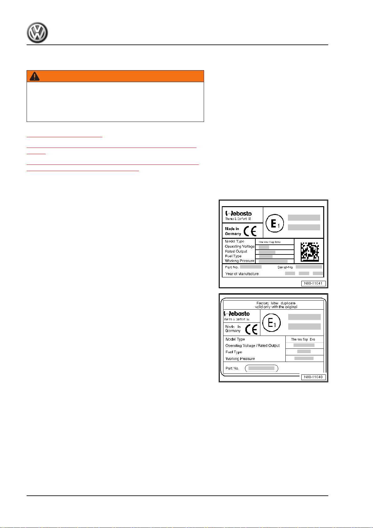
2.1 Type plates . . . . . . . . . . . . . . . . . . . . . . . . . . . . . . . . . . . . . . . . . . . . . . . . . . . . . . . . . . . . . . 4
2.2 Starting conditions for auxiliary/supplementary heater . . . . . . . . . . . . . . . . . . . . . . . . . . . . 4
2.3 Rules for cleanliness when working on auxiliary/supplementary heater and fuel system . . 5
3 Repair instructions . . . . . . . . . . . . . . . . . . . . . . . . . . . . . . . . . . . . . . . . . . . . . . . . . . . . . . . . 6
3.1 Rules for cleanliness . . . . . . . . . . . . . . . . . . . . . . . . . . . . . . . . . . . . . . . . . . . . . . . . . . . . . . 6
3.2 General information . . . . . . . . . . . . . . . . . . . . . . . . . . . . . . . . . . . . . . . . . . . . . . . . . . . . . . 6
3.3 General repair instructions . . . . . . . . . . . . . . . . . . . . . . . . . . . . . . . . . . . . . . . . . . . . . . . . . . 6
3.4 Contact corrosion . . . . . . . . . . . . . . . . . . . . . . . . . . . . . . . . . . . . . . . . . . . . . . . . . . . . . . . . 7
3.5 Nuts and bolts . . . . . . . . . . . . . . . . . . . . . . . . . . . . . . . . . . . . . . . . . . . . . . . . . . . . . . . . . . 7
3.6 Pipe/wire routing and attachment . . . . . . . . . . . . . . . . . . . . . . . . . . . . . . . . . . . . . . . . . . . . 7
4 Hazard classification of high-voltage system . . . . . . . . . . . . . . . . . . . . . . . . . . . . . . . . . . . . 8
82 - Supplementary heating . . . . . . . . . . . . . . . . . . . . . . . . . . . . . . . . . . . . . . . . . . . . 9
1 Overview of fitting locations - auxiliary/supplementary heater . . . . . . . . . . . . . . . . . . . . . . 9
1.1 Overview of fitting locations - components not located in passenger compartment . . . . . . 9
2 Auxiliary/supplementary heater . . . . . . . . . . . . . . . . . . . . . . . . . . . . . . . . . . . . . . . . . . . . . . 10
2.1 Overview of fitting locations - auxiliary/supplementary heater . . . . . . . . . . . . . . . . . . . . . . 10
2.2 Assembly overview - auxiliary/supplementary heater, internal . . . . . . . . . . . . . . . . . . . . . . 12
2.3 Assembly overview - auxiliary/supplementary heater attachments . . . . . . . . . . . . . . . . . . 13
2.4 Removing and installing auxiliary/supplementary heater . . . . . . . . . . . . . . . . . . . . . . . . . . 14
2.5 Removing and installing air intake silencer . . . . . . . . . . . . . . . . . . . . . . . . . . . . . . . . . . . . 16
2.6 Removing and installing circulation pump V55 . . . . . . . . . . . . . . . . . . . . . . . . . . . . . . . . . . 16
2.7 Removing and installing exhaust system . . . . . . . . . . . . . . . . . . . . . . . . . . . . . . . . . . . . . . 18
2.8 Removing and installing cover . . . . . . . . . . . . . . . . . . . . . . . . . . . . . . . . . . . . . . . . . . . . . . 19
2.9 Dismantling and assembling heater unit . . . . . . . . . . . . . . . . . . . . . . . . . . . . . . . . . . . . . . 20
2.10 Removing and installing glow plug with flame monitor Q8 . . . . . . . . . . . . . . . . . . . . . . . . 21
2.11 Removing and installing temperature sensor G18 and overheating sensor G189 . . . . . . 22
2.12 Removing and installing auxiliary heater control unit J364 . . . . . . . . . . . . . . . . . . . . . . . . 23
2.13 Removing and installing combustion air blower V6 . . . . . . . . . . . . . . . . . . . . . . . . . . . . . . 23
2.14 Connector pin assignment for auxiliary/supplementary heater . . . . . . . . . . . . . . . . . . . . . . 23
3 Coolant circuit with auxiliary/supplementary heater . . . . . . . . . . . . . . . . . . . . . . . . . . . . . . 24
3.1 Connection diagram - coolant hoses . . . . . . . . . . . . . . . . . . . . . . . . . . . . . . . . . . . . . . . . . . 24
3.2 Removing and installing heater coolant shut-off valve N279 . . . . . . . . . . . . . . . . . . . . . . 25
4 Fuel supply . . . . . . . . . . . . . . . . . . . . . . . . . . . . . . . . . . . . . . . . . . . . . . . . . . . . . . . . . . . . . . 27
4.1 Checking fuel delivery rate . . . . . . . . . . . . . . . . . . . . . . . . . . . . . . . . . . . . . . . . . . . . . . . . . . 27
4.2 Removing and installing metering pump V54 . . . . . . . . . . . . . . . . . . . . . . . . . . . . . . . . . . 28
5 Regulation of auxiliary/supplementary heater . . . . . . . . . . . . . . . . . . . . . . . . . . . . . . . . . . 30
5.1 Function description . . . . . . . . . . . . . . . . . . . . . . . . . . . . . . . . . . . . . . . . . . . . . . . . . . . . . . 30
5.2 Heating mode . . . . . . . . . . . . . . . . . . . . . . . . . . . . . . . . . . . . . . . . . . . . . . . . . . . . . . . . . . . . 30
5.3 Switching off auxiliary/supplementary heater . . . . . . . . . . . . . . . . . . . . . . . . . . . . . . . . . . . . 31
6 Other controlling and regulating components . . . . . . . . . . . . . . . . . . . . . . . . . . . . . . . . . . . . 32
6.1 Removing and installing ambient temperature sensor . . . . . . . . . . . . . . . . . . . . . . . . . . . . 32
6.2 Removing and installing remote control receiver for auxiliary coolant heater R149 . . . . . . 32
6.3 Functional description of remote control for auxiliary/supplementary heater . . . . . . . . . . . . 32
Transporter 2016 ➤
Auxiliary heater - Edition 04.2020
Contents i

7 Auxiliary air heater . . . . . . . . . . . . . . . . . . . . . . . . . . . . . . . . . . . . . . . . . . . . . . . . . . . . . . . . 37
7.1 Assembly overview - Airtronic D3 auxiliary air heater . . . . . . . . . . . . . . . . . . . . . . . . . . . . 37
7.2 Removing and installing auxiliary air heater Airtronic D3 . . . . . . . . . . . . . . . . . . . . . . . . . . 39
7.3 Removing and installing air intake silencer . . . . . . . . . . . . . . . . . . . . . . . . . . . . . . . . . . . . 42
7.4 Assembly overview - exhaust system . . . . . . . . . . . . . . . . . . . . . . . . . . . . . . . . . . . . . . . . 43
7.5 Removing and installing exhaust system . . . . . . . . . . . . . . . . . . . . . . . . . . . . . . . . . . . . . . 43
7.6 Removing and dismantling auxiliary air heater bracket . . . . . . . . . . . . . . . . . . . . . . . . . . . . 44
7.7 Removing and installing auxiliary air heater control unit J604 . . . . . . . . . . . . . . . . . . . . . . 45
7.8 Removing and installing heater in housing . . . . . . . . . . . . . . . . . . . . . . . . . . . . . . . . . . . . . . 47
7.9 Removing and installing burner unit . . . . . . . . . . . . . . . . . . . . . . . . . . . . . . . . . . . . . . . . . . 48
7.10 Removing and installing glow plug for heater Q9 . . . . . . . . . . . . . . . . . . . . . . . . . . . . . . . . 50
7.11 Removing and installing mantle of Airtronic »D3« . . . . . . . . . . . . . . . . . . . . . . . . . . . . . . . . 51
7.12 Removing and installing flame monitor G64 and overheating sensor G189 (combination
sensor) . . . . . . . . . . . . . . . . . . . . . . . . . . . . . . . . . . . . . . . . . . . . . . . . . . . . . . . . . . . . . . . . 53
7.13 Removing and installing combustion air blower V6 . . . . . . . . . . . . . . . . . . . . . . . . . . . . . . 55
7.14 Removing and installing heat exchanger . . . . . . . . . . . . . . . . . . . . . . . . . . . . . . . . . . . . . . 57
7.15 Removing and installing temperature sensor G18 . . . . . . . . . . . . . . . . . . . . . . . . . . . . . . 59
8 Fuel supply to auxiliary air heater . . . . . . . . . . . . . . . . . . . . . . . . . . . . . . . . . . . . . . . . . . . . 60
8.1 Removing and installing metering pump 2 V386 . . . . . . . . . . . . . . . . . . . . . . . . . . . . . . . . 60
8.2 Checking fuel delivery rate . . . . . . . . . . . . . . . . . . . . . . . . . . . . . . . . . . . . . . . . . . . . . . . . . . 61
9 Regulation of auxiliary air heater . . . . . . . . . . . . . . . . . . . . . . . . . . . . . . . . . . . . . . . . . . . . 63
9.1 Principle of auxiliary air heater operation . . . . . . . . . . . . . . . . . . . . . . . . . . . . . . . . . . . . . . 63
9.2 Function of auxiliary air heater operating and display unit E407 or roof display unit J702
. . . . . . . . . . . . . . . . . . . . . . . . . . . . . . . . . . . . . . . . . . . . . . . . . . . . . . . . . . . . . . . . . . . . . . . . 66
9.3 Removing and installing auxiliary air heater operating and display unit E407 or roof display
unit J702 . . . . . . . . . . . . . . . . . . . . . . . . . . . . . . . . . . . . . . . . . . . . . . . . . . . . . . . . . . . . . . 66
9.4 Removing and installing operating and display unit for camping equipment E153 . . . . . . 67
10 Other components of auxiliary air heater . . . . . . . . . . . . . . . . . . . . . . . . . . . . . . . . . . . . . . 68
10.1 Function description of remote control . . . . . . . . . . . . . . . . . . . . . . . . . . . . . . . . . . . . . . . . 68
Transporter 2016 ➤
Auxiliary heater - Edition 04.2020
ii Contents

00 – Technical data
1 Safety information
(VRL014148; Edition 04.2020)
WARNING
If the vehicle has been converted by ABT e-Line, it is possible
that the repair instructions provided below are no longer valid.
• In this case, the workshop manual in ELSA Pro under the
tab “Superstructures and modifications” provided by ABT e-
Line must be observed and applied.
⇒ “1.1 Safety precautions during work on fuel system”,
page 1
⇒ “1.2 Safety measures when working on vehicles with a start/
stop system”, page 1
⇒ “1.3 Safety precautions when using testers and measuring in‐
struments during a road test”, page 2
⇒ “1.4 Safety precautions when working on the cooling system”,
page 2
⇒ “1.5 Safety precautions for working on vehicles with auxiliary
heater”, page 2
1.1 Safety precautions during work on fuel system
Danger of fire caused by escaping fuel
When the battery is connected and the driver door opens, the door
contact switch activates the fuel pump. Escaping fuel can ignite
and cause a fire.
– Disconnect voltage supply to fuel pump before opening the
fuel system.
Risk of injury from highly pressurised fuel.
The fuel system is pressurised. Injury from fuel spray possible.
Before opening the fuel system:
– Wear protective goggles.
– Wear protective gloves.
– To release pressure, wrap a clean cloth around the connection
and carefully loosen the connection.
1.2 Safety measures when working on vehicles with a start/stop system
Risk of injury due to unexpected motor start
If the vehicle’s start/stop system is activated, the engine can start
unexpectedly. A message in the dash panel insert indicates
whether the start/stop system is activated.
– Deactivate start/stop system by switching off the ignition.
Transporter 2016 ➤
Auxiliary heater - Edition 04.2020
1. Safety information 1

1.3 Safety precautions when using testers and measuring instruments during
a road test
Risk of injury caused by unsecured testing and measuring instru‐
ments
When the front passenger airbag is triggered in an accident, in‐
sufficiently secured testing and measuring instruments become
dangerous projectiles.
– Secure testing and measuring instruments on the rear seat.
or
– Have a second person operate the test and measuring equip‐
ment on the rear seat.
1.4 Safety precautions when working on the cooling system
Danger of scalding by hot coolant
On a warm engine, the cooling system is under high pressure.
Danger of scalding by steam and hot coolant.
– Wear protective gloves.
– Wear protective goggles.
– Reduce excess pressure by covering cap of coolant expan‐
sion tank with cloths and opening it carefully.
1.5 Safety precautions for working on vehicles with auxiliary heater
Danger of fire and explosion from auxiliary heater
In fire and explosion-endangered areas, a spark or the high tem‐
perature of the auxiliary heater can cause a fire or an explosion.
Risk of burns.
– Switch the auxiliary heater off in fire and explosion-endan‐
gered areas.
Danger of poisoning from exhaust fumes
Auxiliary heaters produce poisonous exhaust fumes. Risk of poi‐
soning and injuries to respiratory system.
– In closed areas, switch on the auxiliary heater only when it is
connected to an exhaust extractor system.
– In closed areas without an exhaust extractor system, switch
the auxiliary heater off.
Transporter 2016 ➤
Auxiliary heater - Edition 04.2020
2 Rep. gr.00 - Technical data

Risk of damage when starting the engine
If components of the fuel system or coolant circuit of the auxiliary
heater are removed or opened, there is a possibility of causing
damage to the auxiliary heater.
– Never attempt to start the engine when components are re‐
moved or opened.
Malfunction caused by air in the fuel supply system
After work has been performed on the fuel tank or the fuel delivery
unit, the metering pump will draw air and supply it to the auxiliary
heater. The air in the fuel system may cause the auxiliary heater
to malfunction.
– Fill fuel take-off pipe with fuel.
Risk of accidents and risk of injury due to activated timer of aux‐
iliary heater
If the vehicle’s timer for the auxiliary heater is active, the heater
may switch on unexpectedly. This poses a risk of poisoning from
exhaust gases, a risk of burns caused by hot auxiliary heater
components as well as a risk of fire and explosions caused by
high temperatures.
– Deactivate timer for auxiliary heater.
Transporter 2016 ➤
Auxiliary heater - Edition 04.2020
1. Safety information 3

2 General information
WARNING
If the vehicle has been converted by ABT e-Line, it is possible
that the repair instructions provided below are no longer valid.
• In this case, the workshop manual in ELSA Pro under the
tab “Superstructures and modifications” provided by ABT e-
Line must be observed and applied.
⇒ “2.1 Type plates”, page 4
⇒ “2.2 Starting conditions for auxiliary/supplementary heater”,
page 4
⇒ “2.3 Rules for cleanliness when working on auxiliary/supple‐
mentary heater and fuel system”, page 5
2.1 Type plates
There are different types of type plates.
When the auxiliary heater is renewed, check the type plate and
the duplicate plate and replace as necessary.
Type plate on auxiliary/supplementary heaters
♦ The date of first use is entered on the lower part of manufac‐
turer's plate.
♦ The year the unit was first put into use must be entered on the
Genuine part manufacturer's plate.
Duplicate type plate for auxiliary/supplementary heaters
♦ In the engine compartment of the vehicle, there is a second
(duplicate) type plate attached to the right of the lock carrier
(when looking in direction of travel). If there is any doubt con‐
cerning the type of the auxiliary/supplementary heater, always
observe the type plate attached directly to the auxiliary/sup‐
plementary heater.
2.2 Starting conditions for auxiliary/supple‐
mentary heater
♦ Engine type OK (diesel/petrol)
♦ Terminal 15 (ignition) on
♦ Engine speed >600 rpm
♦ Coolant temperature <69 °C
♦ Ambient temperature <5 C
♦ Reserve fuel level not reached
♦ Line filling carried out
Transporter 2016 ➤
Auxiliary heater - Edition 04.2020
4 Rep. gr.00 - Technical data

♦ On-board network manager not active
♦ No crash switch-off
♦ No event memory entries blocking start procedure
2.3 Rules for cleanliness when working on
auxiliary/supplementary heater and fuel
system
♦ Thoroughly clean all connections and adjacent areas before
disconnecting.
♦ Place parts that have been removed on a clean surface (use
sheeting or paper, no cloths containing lint) and cover.
♦ If repair work cannot be performed immediately, carefully cov‐
er or seal opened components.
♦ Only install clean parts:
– Remove replacement parts from their packages only immedi‐
ately before installing them.
– Do not use any parts which have not been stored in their pack‐
aging (e.g. in a tool box).
♦ If fuel line has been opened:
– Do not work with compressed air.
– Do not move the vehicle.
– Do not start engine.
– Do not switch auxiliary heater on.
Transporter 2016 ➤
Auxiliary heater - Edition 04.2020
2. General information 5

3 Repair instructions
WARNING
If the vehicle has been converted by ABT e-Line, it is possible
that the repair instructions provided below are no longer valid.
• In this case, the workshop manual in ELSA Pro under the
tab “Superstructures and modifications” provided by ABT e-
Line must be observed and applied.
⇒ “3.1 Rules for cleanliness”, page 6
⇒ “3.2 General information”, page 6
⇒ “3.3 General repair instructions”, page 6
⇒ “3.4 Contact corrosion”, page 7
⇒ “3.6 Pipe/wire routing and attachment”, page 7
3.1 Rules for cleanliness
Even small amounts of contamination/soiling can lead to defects.
Therefore, observe the following rules for cleanliness when work‐
ing on the air conditioning system:
♦ Seal open pipes and connections immediately with clean
plugs for example from the engine bung set - VAS 6122- .
♦ Place removed parts on a clean surface and cover them over.
Use only lint-free cloths.
♦ If repair work cannot be performed immediately, carefully cov‐
er or seal opened components.
♦ Install only clean parts; do not remove new parts from pack‐
aging until immediately before installing. Do not use parts that
have been stored outside their packaging (e.g. in tool boxes).
♦ If system is open, do not work with compressed air.
♦ Protect disconnected electrical connectors from dirt and water,
and only reconnect them in dry condition.
3.2 General information
♦ The engine/motor control unit has a self-diagnosis capability.
Before carrying out repairs and for fault finding, first read event
memory.
♦ For trouble-free operation of electrical components, a voltage
of at least 11.5 volts is necessary.
♦ Do not use sealants containing silicone. Particles of silicone
drawn into the engine will not be burnt in the engine and dam‐
age the lambda probe.
♦ Vehicles are fitted with a crash fuel shut-off circuit. It reduces
the danger of a fire in a crash as the fuel pump is switched off
via the fuel pump relay.
♦ The system also improves the starting characteristics of the
engine. When the driver door is opened, the fuel pump is ac‐
tivated for 2 seconds to build up pressure in the fuel system.
3.3 General repair instructions
Never attempt to repair any components of the auxiliary/supple‐
mentary heater. Defective components must be replaced with
Genuine parts.
Transporter 2016 ➤
Auxiliary heater - Edition 04.2020
6 Rep. gr.00 - Technical data

– Read self-diagnosis of auxiliary/supplementary heater using
⇒ Vehicle diagnostic tester.
– When parts of the fuel system are removed or renewed, en‐
sure that all components for fuel delivery to the auxiliary/
supplementary heater are properly installed.
– Mark coolant hoses before removing to avoid any confusion
when reconnecting.
Following repair work in the vicinity of the auxiliary/supplementary
heater fuel line, check the following points:
♦ that the fuel lines are routed flush with the vehicle underbody
and are protected against mechanical damage.
♦ that the auxiliary/supplementary heater fuel line is protected
from heating which might disturb operation.
♦ The fuel line does not come in contact with parts that become
hot.
3.4 Contact corrosion
Contact corrosion can occur if unsuitable fasteners (bolts, nuts,
washers, etc.) are used.
For this reason, only fasteners with a special surface coating are
installed in the vehicle.
Furthermore, rubber and plastic components as well as adhe‐
sives are made of non-conductive materials.
If there is any doubt about the suitability of parts, a general rule
is to use new parts ⇒ Electronic parts catalogue (ETKA) .
3.5 Nuts and bolts
♦ Specified torques given are for unlubricated nuts and bolts.
♦ Always renew self-locking bolts and nuts.
♦ Always renew nuts and bolts with turning further angle.
3.6 Pipe/wire routing and attachment
Risk of damage to lines
Lines may become damaged by moving or hot components.
– Route lines in their original positions.
– Ensure there is sufficient clearance to moving or hot compo‐
nents.
Transporter 2016 ➤
Auxiliary heater - Edition 04.2020
3. Repair instructions 7

4 Hazard classification of high-voltage
system
DANGER
The vehicle’s high-voltage system and the high-voltage battery
are dangerous and can cause burns or other injuries and even
lead to a fatal electric shock.
– Any work on the high-voltage system, or on systems which
could be indirectly affected by it, must only be carried out by
properly trained and qualified expert personnel.
– In the event of queries or uncertainties regarding the terms
"high-voltage technician" or "high-voltage expert", or those
concerning the high-voltage system, the responsible import‐
er must be contacted before any work is undertaken.
– Any repair work must be performed in accordance with ap‐
plicable laws and regulations, the state-of-the-art technolo‐
gy, any relevant accident prevention regulations (in Germa‐
ny, including but not limited to the Information of the German
Social Accident Insurance (DGUV) 200-005 – Qualification
training for work on vehicles with high-voltage systems), as
well as this workshop manual.
Procedure for vehicles electrified by ABT e-Line
Please observe the Workshop Manuals available in ElsaPro, tab
“Superstructures and modifications”.
If you have no access to ElsaPro, you can also obtain the relevant
manuals from ABT e-Line.
Transporter 2016 ➤
Auxiliary heater - Edition 04.2020
8 Rep. gr.00 - Technical data

82 – Supplementary heating
1 Overview of fitting locations - auxili‐
ary/supplementary heater
⇒ “1.1 Overview of fitting locations - components not located in
passenger compartment”, page 9
1.1 Overview of fitting locations - components not located in passenger com‐
partment
1 - Fuel tank
❑ Removing and installing
⇒ Fuel supply - diesel
engines; Rep. gr. 20 ;
Fuel tank; Removing
and installing fuel tank .
2 - Fuel line
3 - Fuel gauge sender - G-
❑ Removing and installing
⇒ Rep. gr. 20 ; Fuel de‐
livery unit/fuel gauge
sender; Removing and
installing fuel delivery
unit/fuel gauge sender
4 - Air intake silencer
❑ Removing and installing
⇒ page 16
5 - Exhaust system
❑ Removing and installing
⇒ page 18
6 - Auxiliary heater
❑ Removing and installing
⇒ page 10
7 - Metering pump - V54-
❑ Removing and installing
⇒ page 28
❑ Testing quantity of fuel
delivered ⇒ page 27
8 - Circulation pump - V55-
❑ Removing and installing
⇒ page 16
9 - Remote control receiver for
auxiliary coolant heater -
R149- or remote control receiver for auxiliary heating - R64-
❑ Removing and installing ⇒ page 32
10 - Shut-off valve for heater coolant - N279-
❑ Removing and installing ⇒ page 25
11 - Ambient temperature sensor - G17-
❑ Removing and installing ⇒ Heating, air conditioning system; Rep. gr. 87 ; Other control components;
Removing and installing ambient temperature sensor G17
Transporter 2016 ➤
Auxiliary heater - Edition 04.2020
1. Overview of fitting locations - auxiliary/supplementary heater 9

2 Auxiliary/supplementary heater
⇒ “2.1 Overview of fitting locations - auxiliary/supplementary heat‐
er”, page 10
⇒ “2.2 Assembly overview - auxiliary/supplementary heater, in‐
ternal”, page 12
⇒ “2.3 Assembly overview - auxiliary/supplementary heater at‐
tachments”, page 13
⇒ “2.4 Removing and installing auxiliary/supplementary heater”,
page 14
⇒ “2.5 Removing and installing air intake silencer”, page 16
⇒ “2.6 Removing and installing circulation pump V55 ”,
page 16
⇒ “2.7 Removing and installing exhaust system”, page 18
⇒ “2.8 Removing and installing cover”, page 19
⇒ “2.9 Dismantling and assembling heater unit”, page 20
⇒ “2.10 Removing and installing glow plug with flame monitor Q8
”, page 21
⇒ “2.11 Removing and installing temperature sensor G18 and
overheating sensor G189 ”, page 22
⇒ “2.12 Removing and installing auxiliary heater control unit J364
”, page 23
⇒ “2.14 Connector pin assignment for auxiliary/supplementary
heater”, page 23
2.1 Overview of fitting locations - auxiliary/supplementary heater
Transporter 2016 ➤
Auxiliary heater - Edition 04.2020
10 Rep. gr.82 - Supplementary heating

1 - Auxiliary/supplementary
heater
❑ Removing and installing
⇒ page 14
❑ Dismantling and assem‐
bling ⇒ page 20
2 - Bracket for auxiliary/supple‐
mentary heater
3 - Bracket
4 - Rubber mounting
5 - Electrical connector
6 - Coolant hose
7 - Circulation pump - V55-
❑ Removing and installing
⇒ page 16
8 - Bracket
❑ For circulation pump -
V55-
9 - Exhaust system
❑ Removing and installing
⇒ page 18
10 - Bracket
❑ For circulation pump -
V55-
11 - Bolt
❑ 6 Nm
12 - Rubber mounting
13 - Bolt
❑ 20 Nm
Transporter 2016 ➤
Auxiliary heater - Edition 04.2020
2. Auxiliary/supplementary heater 11

2.2 Assembly overview - auxiliary/supplementary heater, internal
1 - Bolts
❑ Qty. 3
❑ 7 Nm
2 - Heat exchanger
❑ Removing and installing
⇒ page 20
3 - Seal
❑ Must be renewed each
time after opening
❑ Observe installation po‐
sition
4 - Combustion chamber insert
❑ Removing and installing
⇒ page 20
5 - Glow plug with flame moni‐
tor - Q8-
❑ Must be properly seated
❑ Removing and installing
⇒ page 21
6 - Cover
❑ For auxiliary heater con‐
trol unit - J364-
❑ Removing and installing
⇒ page 19
7 - Cover
8 - Auxiliary heater control unit
- J364- with combustion air
blower - V6-
Note
The auxiliary heater control unit -
J364- and the combustion air blower
- V6- with housing form one compo‐
nent and cannot be dismantled. The
reason is the seal between the aux‐
iliary heater control unit - J364- and
the housing.
9 - Noise insulation
10 - Cover
❑ Removing and installing ⇒ page 19
11 - Union
❑ Mark installation position before removing
12 - Seals
❑ Renew after removal
13 - Support plate
14 - Bolt
❑ 4 Nm
Transporter 2016 ➤
Auxiliary heater - Edition 04.2020
12 Rep. gr.82 - Supplementary heating

15 - Union
❑ Mark installation position before removing
16 - Temperature sensor - G18-
❑ Removing and installing ⇒ page 22
17 - Retaining spring
18 - Bolt
❑ 4 Nm
19 - Overheating sensor - G189-
❑ Removing and installing ⇒ page 22
2.3 Assembly overview - auxiliary/supplementary heater attachments
1 - Bracket
❑ For auxiliary heater
2 - Bolts
❑ Qty. 3
❑ 6 Nm
3 - Rubber mounting
4 - Air intake silencer
❑ Removing and installing
⇒ page 16
5 - Exhaust system
❑ Removing and installing
⇒ page 18
6 - Auxiliary/supplementary
heater
7 - Bracket
❑ For circulation pump -
V55- and air intake si‐
lencer
8 - Bolts
❑ Qty. 2
❑ For bracket of circula‐
tion pump - V55- and air
intake silencer
❑ 6 Nm
9 - Bracket
❑ For circulation pump -
V55-
10 - Circulation pump - V55-
❑ Removing and installing
⇒ page 16
11 - Clip
12 - Coolant hose
13 - Bolt
❑ 8 Nm
Transporter 2016 ➤
Auxiliary heater - Edition 04.2020
2. Auxiliary/supplementary heater 13

14 - Coolant hose
15 - Bolt
❑ 20 Nm
16 - Rubber mounting
2.4 Removing and installing auxiliary/sup‐
plementary heater
Special tools and workshop equipment required
♦ Hose clamps to 25 mm - 3094-
♦ Engine bung set - VAS 6122-
♦ Drip tray for workshop hoist - VAS 6208-
♦ Vehicle diagnostic tester
Removing
– Connect ⇒ Vehicle diagnostic tester and start function “Renew
heater” under “Guided Fault Finding” or “Guided Functions”.
– Disconnect battery ⇒ Electrical system; Rep. gr. 27 ; Battery;
Disconnecting and reconnecting battery .
Transporter 2016 ➤
Auxiliary heater - Edition 04.2020
14 Rep. gr.82 - Supplementary heating

– Remove left underbody cladding ⇒ General body repairs, ex‐
terior; Rep. gr. 66 ; Underbody cladding; Assembly overview
- underbody cladding .
– Clamp off coolant hoses of auxiliary heater using hose clamps
up to 25 mm - 3094- .
– Open hose clips of coolant hoses.
– Place drip tray for workshop hoist - VAS 6208- underneath.
CAUTION
On a warm engine, the cooling system is under high pressure.
Danger of scalding by steam and hot coolant.
Skin and other parts of the body may be scalded.
– Wear protective gloves.
– Wear protective goggles.
– Reduce excess pressure by covering cap of coolant expan‐
sion tank with cloths and opening it carefully.
– Pull off coolant hoses from auxiliary heater.
CAUTION
The fuel system is pressurised.
Danger of injury caused by fuel spray.
– Wear protective goggles.
– Wear protective gloves.
– To release pressure, wrap a clean cloth around the connec‐
tion and carefully loosen the connection.
– Pull off fuel line from auxiliary heater to metering pump - V54-
and seal with engine bung set - VAS 6122- .
– Secure auxiliary heater with welding wire to prevent it from
falling down.
– Separate electrical connectors.
– Unscrew bolt -3- from bracket -1-.
Note
Observe the installation position of the rubber disc -2-.
Transporter 2016 ➤
Auxiliary heater - Edition 04.2020
2. Auxiliary/supplementary heater 15

– Lower auxiliary heater -1- with bracket -2- in direction of
-arrow-.
– Pull out auxiliary heater -1- with bracket -2- from rubber mount‐
ings -3-.
Installing
Install in reverse order of removal, observing the following:
– Bleed coolant circuit ⇒ Rep. gr. 19 ; Cooling system, coolant;
Draining and filling coolant .
Specified torques
♦⇒ “2.3 Assembly overview - auxiliary/supplementary heater
attachments”, page 13
2.5 Removing and installing air intake si‐
lencer
Removing
– Remove left underbody cladding ⇒ General body repairs, ex‐
terior; Rep. gr. 66 ; Underbody cladding; Assembly overview
- underbody cladding .
– Unscrew bolts -3-.
– Lower auxiliary heater -2- in direction of -arrow A-.
Note
The lines and coolant hoses remain connected.
– Release spreader clip of air intake silencer -1- in direction of
-arrow B-.
– Pull off air intake silencer from auxiliary heater -2-.
Installing
Install in reverse order of removal, observing the following:
Note
♦
The air intake silencer must not touch the auxiliary/supple‐
mentary heater housing.
♦
Do not kink or crush aluminium pipe.
Specified torques
♦⇒ “2.3 Assembly overview - auxiliary/supplementary heater
attachments”, page 13
2.6 Removing and installing circulation
pump - V55-
Special tools and workshop equipment required
Transporter 2016 ➤
Auxiliary heater - Edition 04.2020
16 Rep. gr.82 - Supplementary heating
Other manuals for Transporter 2016
1
Table of contents
Popular Heater manuals by other brands

TESY
TESY HL-255V PTC Usage and Storage Instructions

Trotec
Trotec IDS 900 Original instructions

Empire Heating Systems
Empire Heating Systems RH-50-7 Installation instructions and owner's manual

Phormalab
Phormalab hotdoor HCA01 Assembly instructions

Marley
Marley FZL Series Installation & maintenance instructions

Kambrook
Kambrook KCE340GRY Instruction booklet