Abestorm Water Damage Series User manual

User’s Manual
Note: as we keep upgrading our product,we reserve the right to modify the product
without natice in advance.
Abestorm Solutions INC
Water Damage Series
Add:Berlin
Tel: +44 (20) 81243974
Email: www.abestorm.com
Fire Waving 200 Heater

Operation and control instructions
Duct instructions
Transportation and storage
Maintenance
Unit Diagram
Specifications
Installation Requirements
Spare Parts
Warranty
Important Notes
Warranty Registration
Before first use
Abestorm Warranty Steps:
Warranty Exclusions 16
15
15
14
13
13
12
10
10
8
4
4
2
3
Important Notes
To avoid the risk of burns, keep your hands and body off the heater when it is in use.
1
Use the heater handles when operating it and or moving it.
Keep all combustible materials such as paper, timber, clothes, furniture. pillows, carpets and
the like, away from the heater, especially when in use.
Note that the heart is meant for use for short periods in emergency cold situations. You should
not deploy it for comfort use frequently. Check out the NFPA 70, article number 590
Unplug the unit once you are through using it
Avoid using the unit 1. if the cords are damaged
2. when it has malfunctioned
3. when plug is faulty
4. after the unit falls
5. when damaged
If and when you encounter the above problems with the unit, take it to an authorised technician
for servicing. The unit was designed for use indoors only. Do not ever try to use it outdoors;
the risk of malfunction would be significantly high, especially in wet conditions. It may also
not perform as well as it does indoors.
Note that you should not use the hater in wet environments such as bathrooms, kitchens and
similar locations where there is high humidity and wetness. Avoid keeping or stationing the
heater where it can slide and fall into water.
Avoid running the cord under carpets, or covering it with any materials. Similarly, there should
be no routing under furniture or any other equipment.
Only run the cord in spaces that have not traffic so as to prevent people from tripping on it.
Turn the controls of the unit off before you disconnect it from the power source.
You should only connect the unit to GFCI sources that are properly grounded
Watch out for any foreign objects finding their way into the unit through openings and
ventilation. These could trigger a malfunction and consequent fire. They could also cause
your heater to be damaged.
Never block the air inlets to the unit. The exhaust should also be kept open. Avoid using the
unit on relatively soft surfaces because they could easily catch a fire.
Note that the unit operations involve some sparking elements inside. Therefore, it is not
suitable to use where there are flammable substances such s gas or kerosene, paint or
similar highly flammable materials.
Only deploy the device for the purposes stated in this manual.
Only use the device according the instructions provided in this user manual. Using it in any
other way could lead to accidents and damages. The manufacturer will not be held liable
in such events
Only use the following cords for 120V
1.12AWG
2. Over 1440 Watts size rating
2

Warranty Registration
Your Heater comes with an extensive warranty. To register your unit simply fill
out and return the warranty form provided in your box.Heater
For future refereirce, write down the model, serial number, and date of purchase for
your . This information is necessary for seeking assistance in the future and
can be found on the data label on the sde of the unit.
Heater
Model Number: FireWaving 200
Serial Number:
Date of Number:
For additional questions concerning your dehumidifier, contact your local installer or
call Abestorm at 44(20)81243974.
Before first use
The unit features
2 duct rings with an adaptor kit inside the storage section.
A three-millimeter Allen wrench for installing the component.
Required: Install the Reactivation Air Outlet duct ring. Attach the Reactivation
Duct Ring (Figure B)
Optional: Install Air Inlet duct ring Fix on the inlet with the included
thumbscrews, (Figure B)
Optional: Install Process Air Outlet screws
You may install the Process Air Outlet Adaptor Kit using the included offset
screws, (Figure B).
Operation and control instructions
Place the equipment away from obstructions that may hinder the airflow in and
out of the dehumidifier. Route a reactivation outlet duct outdoors through a dryer
vent or window adapter.
Positioning the Dehumidifier
3 4
Specifications
Power 115V/60HZ
Amperages(max.) 24Amperes
Amperages(at 80℉/60%RH) Circuit 1:10.7
Circuit 1:10.8
Process air 395 CFM
65 CFM
Reactivation air
Water removal capacity
(at 80°F/60%RH) 118 pints per day | 55.8 L per/day
Weight
Dimensions (H × W × D)
33.13 × 21.14 × 20.25 in.
(With handle upright = 42. 250 in.)
84.15 × 53.7 × 51.4 cm
(With handle upright = 107.3 cm.)
95 lbs. | 43.1 kg
Air filter
Safety
F590 (24 pk)
ETL listed to CSA dehumidifier
standards
2 Operation
2.1 Moving the Unit
It is recommended that the FireWaving 200 is always upright when it is transported
with a vehicle. The device is fitted with rubbers on the endings to allow it to stack
without damage resulting from impact. Further, straining straps should be used if
you are transporting several units at a go. The strapping helps to tie the devices in
place strongly and reduce the possibility of impact damage to themselves or even
injuring people.
2.2 Electrical Requirements
You will need a 120VAC power source to operate the FireWaving 200’s blower, first
heater circuit and the control. It is fitted with three more elements that are
separately powered with additional receptacles and cords. Each of the 120VAC
heating parts needs connection to cord and an appropriate receptacle rating of 15A
or higher. Each heating element requires a cord and a receptacle. The power
cords must be of appropriate size. They should be of a minimum of 12GA and
higher measuring not more than 25ft. If they are longer, they can be longer should
have a triple blade grounding plug type. There is an adaptor for connection to
receptacles with two slots.
Proper Grounding
The grounding plug must be fastened to a permanent ground point such as an
installed grounded outlet box. If the triple slot grounded receptacle is available,
there is no need to use the adopter
You can duct the Abestorm Firewaving 200 right at the inlet, or both the inlet
and outlet. The unit is designed to accommodate an 8’’ duct that is also flexible.
Note that you should keep in mind the outlet temperatures whenever you are
choosing the flexible outlet duct. The temperature increase of the air is usually
between 50 to 800F. Additional ducting increases the temperatures at the outlet
because the extra ducting decreases the airflow. The increase in temperature can
be up to 400F.
2.3 Ducting
Caution
You must never use the Mylar ducting because it can easily cause a fire outbreak.

49-109J F533 2 Legend Brands, Inc.
are properly grounded. Do not modify the plugs pro-
vided with the appliance – if the plugs do not fit the
outlets, have proper outlets installed by a qualified
electrician.
This equipment is for use on circuits with a nominal rat-
ing of no more than 120V.
Handle the unit carefully
Always operate the unit on a stable, level surface. Do
not drop, throw, or place where it could fall. Rough treat-
ment can damage the unit, and may create a hazardous
condition or void the warranty.
This unit intended for household and commercial use.
BEFORE FIRST USE
The unit is shipped with two duct rings and an adaptor kit
packed inside the storage compartment. A 3 mm Allen
wrench is required for installation of these components.
Required: Install Reactivation Air Outlet duct ring
Install the Reactivation Duct Ring, See Fig. B.
Optional: Install Air Inlet duct ring
Attach to inlet with the thumbscrews provided. See Fig.
B.
Optional: Install Process Air Outlet offset screws
The Process Air Outlet Adaptor Kit may be installed us-
ing the offset screws provided. See Fig. B.
CONTROLS AND OPERATING
INSTRUCTIONS
Positioning the Dehumidifier
For best results, operate your dehumidifier in an en-
closed area. Close all doors and windows that open to
the outside to maximize water removal efficiency. Place
your dehumidifier away from any obstructions that could
block airflow into and out of the unit. Duct reactivation
outlet outdoors through window adapter or dryer vent.
Plug in electrical cords
Always plug the cords firmly into the sockets in the
top compartment first, then into the wall outlets. En-
sure that the cords are routed properly through the
cord cutout notch before closing the storage com-
partment lid.
NOTICE: The power cords of the DriTec must be
plugged into separate GFCI-protected 120V outlets rated
for at least 15A.
CONTROL PANEL
Press the ON/OFF to turn the unit on.
Fig. A: Parts Identification
Air filter
Power sockets inside
compartment. Stor-
age for power cords,
react ducting.
Air inlet
Reactivation
Air Outlet
(installation
of duct re-
quired)
Control panel
Process Air Out-
let (optional duct
attachment kit
provided)
For maximum efficiency, use both circuits while ensuring that the green light illuminates.
However, the dehumidifier may run on one power cord if the second circuit is not
available. Plug into Circuit 1. When using a single power cable, the dehumidifier
operates at half the rated performance.
Positioning the Dehumidifier
When connecting the dehumidifier to power for the first time, the control panel briefly cycles
through various readouts. This is a regular self-diagnosis procedure for the unit; thus,
no intervention by the user is required.
Ducting Setup
Note, the unit is designed for indoor use only. The equipment should not be exposed to snow or rain.
If any electrical component becomes wet, allow for thorough drying before operating the unit.
Reactivation Outlet Ducting
To attach the ducting on the duct ring, use the provided duct clamp. Ensure that the reactivation air is ducted
to the outside.
NOTICE
During operation, condensate may collect inside the reactivation duct. Water should not run back into the unit;
this could damage the unit. Or lead to a shock hazard.
Note: The temperatures in the React Out ducting may reach 66°C (150°F).
Only use the heat-rated ducting provided.
Process Outlet Ducting
The out air should be ducted, where more drying is required. It should only be used with a lay-flat ducting.
Maximum Ducting length
For maximum performance, ducting should not exceed these lengths:
Reactivation air: 20 feet |. 6m
Inlet air: 30 feet |. 9.1m
Process air: 10feet | 3 m
For additional ducting options, see figure C
5 6
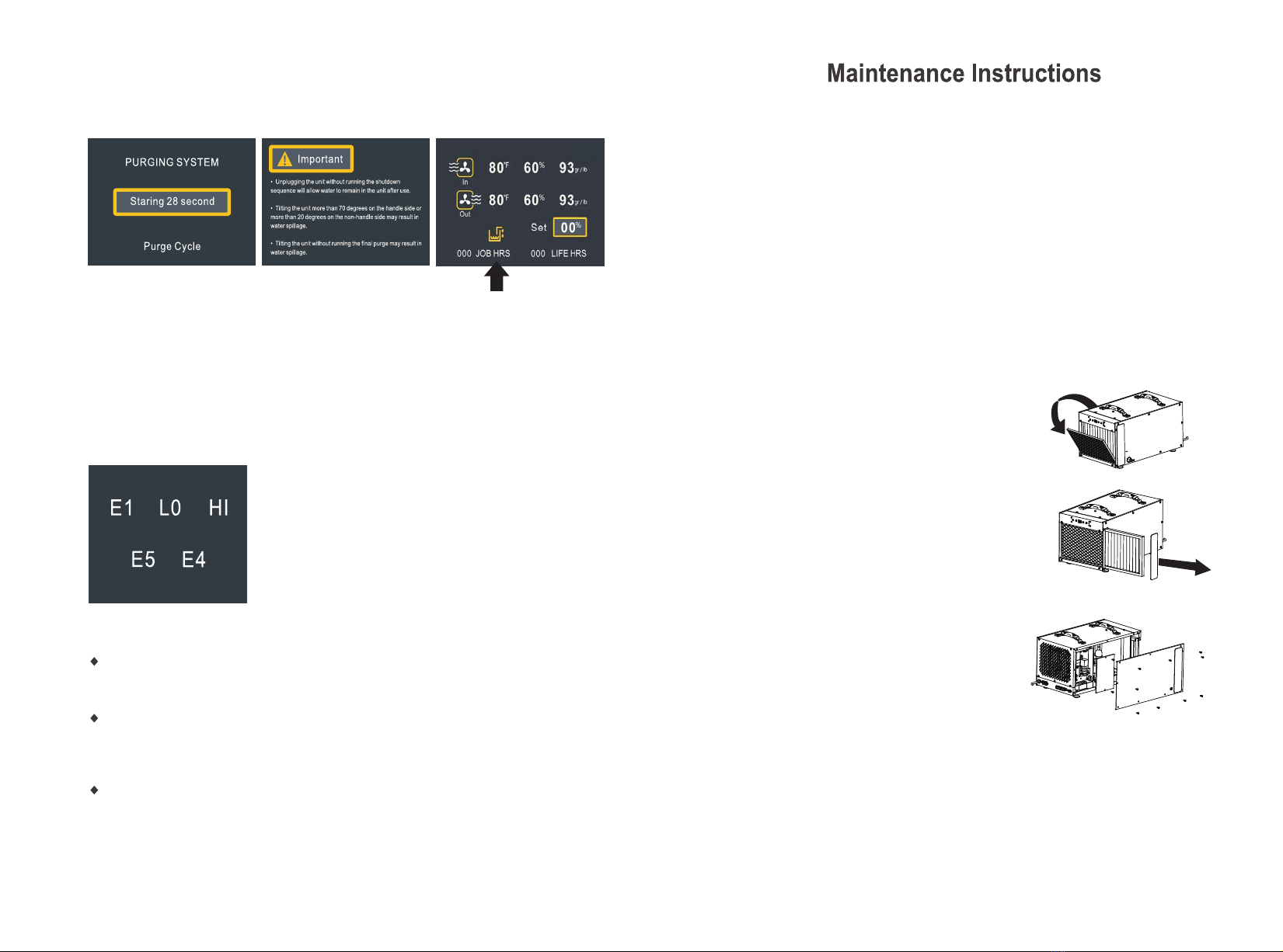
LCD Display Instructions
The machine displays when it is not
working. (Power off state but have
electricity)
PURGE
PURGE
PURGE
PURGE
PURGE
PURGE
1. When the machine is powered on but not working:
Boot display: The LOGO interface
will disappear after 2 seconds. Enter
the following interface
2. Main interface display of dehumidification state:
The following information is displayed when the machine is working:
Refers to the working time, which is defined as the time from
starting up to shutting down,including the defrost time during
the period, and the standby time after the humidity. The
submenu has a reset function. If not, the working time shall
be accumulated.
Total time 9999 hours, the largest cumulative to the largest
automatically reset after restart, and display units for hours.
(round off).
000 JOB HRS:
(after power on, the buzzer makes a sound)
3.1
Device name displayed on the screen
“Indicates”:Do I need to clear out this time?",
press ">"if you need to clear. When the operation
is completed, the working time of the main
interface and the working time of this interface
will be reset and started to be instant again.
After accumulation (9999), clean up and round.
3.2
3.3
“Coil Temp 000℃ ”: Used to display the current
temperature of the coil.When it is below zero,
the "-" symbol is displayed in front. "-" is not
required on zero.
Only applicable to app-controlled dehumidifier.
000 LIFE HRS:
Refers to the total working time, i.e. the total working time (hours), which is in hours.(press the mode key +
select the confirmation key, and the total working time will be cleaned after 3 seconds.
IN/OUT 00℉ 00% 00 gr / lb:
Indicates the temperature, humidity and moisture content of the air inlet and outlet
{GPP - grain per pound (gr/lb)}.
Indicates set humidity.
Set 00%:
If the main interface does not operate for 10 minutes, the screen will go out.Press any key to
wake up.
Other icons light up or flicker when opened
The total working time is the accumulation of each working time (hours) in hours. (Press the
mode key + select to confirmation key, and the total working time will be cleaned after 3 seconds.
3.Dehumidification status submenu interface display

3.8
"Humidistat Setpoint 00%":Used for setting dehumidification
mode humidity.Press ">" to set the humidity. The adjustment
range of humidity setting is between 25 and 80%.
Each key rises or falls 5%, which can be recycled.
When the setting is completed,do not operate for 5 seconds
and begin to take effect.(Otherwise, the compressor will be
shut down immediately after it is below ambient humidity at
the time of setting.) Humidity below 25 percents "CO" mode
recyclable.The main interface displays the set parameters.
4. Main interface frosting status display:
The machine will display this after defrost when running
When the machine is running normally, “Deffrost
SHUTDOWN IN 06:00” will occurs in the
interface after defrosting. It’s defrost countdown
use seconds as units. This screen displays only
3 seconds. Displays the previous interface and
status after restoration.If it is the home screen,
the frost icon will flash.
When the user is operating in the submenu, the
machine is in the frosting state.At this point, the
frosting interface displays 3 seconds, and returns
to the submenu program in the background
countdown.When the user returns to the main
interface without any operation, the frosting state
is displayed inthe main interface in the way of
icon flicker.
5. Compressor on waiting interface display
Compressor protection time not shown:
“Compressor ready IN 03:00” indicates : That the
interface will be displayed when the compression is
in a protected state. (including power-on and shutdown,
the humidity rises immediately after the arrival of L0
HI, and the shutdown resumesimmediately after the
emergence of L0 HI).Displays the countdown in seconds.If the
above situation does not occur within 3 minutes, it is not
shown.
3.4
3.5.1
The power down time is adjusted according to">"
and the power down time increases from 3 to 20
minutes (3-5-10-15-20), which is the so-called
stop time of the fan after shutdown, in order to
better drain the water.Factory set for 3 minutes.
(the other state of the fan is still 15 seconds.)
3.5.2
The screen displays when you press shut
down:
Indicates: the fan is closed after a few minutes,
and the standby page UNIT OFF is displayed after
the fan is closed.
3.6 3.7
“Temp Units ℉/℃”:Used for temperature scale
switching.Press the ">" button to switch ℉/℃,
after switch symbol of corresponding parts is also
changing.
“MOISTURE CONTENT UNITS”:It is used to
switch the unit of GPP value with moisture
content. Press > to switch the Ib or Kg, after
switch symbol of corresponding parts is also
changing.
LB
Wifi hotspot: factory setting is "0FF",
press > to enable wifi hotspot and switch
ON/OFF.The device can transmit data and receive
APP commands.The icon flickers when connected
on the main interface. After successful connection,
the icon displays normally.
Only applicable to app-controlled dehumidifier.
7 8

Transportation and storage
Note: Handle the equipment with caution. Subjecting it to rough handling may cause
damage and create a perilous condition or render the warranty void.
The control panel should NOT be exposed to rain, moisture, or snow.
Ensure that the unit is secured before storage and transporting to avoid damaging
impact on the internal components.
During transportation, ensure that the unit is secured to prevent possible sliding and
cause injury to the occupants in the vehicle.
Maintenance
**For more detailed instructions, visit www.unipdry.com**
WARNING: Always unplug the unit before doing any maintenance.
Cleaning the Machine Body
• Use a soft, damp cloth to clean the exterior of unit. Do not use any
soap or solvents
Coil Maintenance
Once per year, clean the coils with an approved coil cleaner. The coil cleaner should be a self-rinsing,
foaming, cleaner, such as WEB® Coil Cleaner.
Cleaning the Filter
1. Unplug the unit.
2. For PreFilter:
a. Remove prefilter from inlet of machine.
b. Vacuum or wash with warm water (no soap).
3. For MERV-10/HEPA/Carbon Filters:
a. Replace as necessary- we
recommend checking the filters
at least 1x/year
Electrical Access
•
• Remove the screw on the
control board cover.
Unscrew the 13 screws on the side panel.
9 10
6. Water Pump working interface display
Compressor protection time not shown:
“Pump working countdown”: indicates: No matter in which
working state and interface, as long as the pump works, this
interface appears and counts down to 28 seconds.However,
the interface only displays the previous working status and
interface after 3 seconds.For example, after 3 seconds, there
is a drainage icon on the main interface and it
will flash until the drainage is finished.
7.Interface display in case of failure
Machine running time fault display:
Make fault judgment and take corresponding actions after starting
up. Regardless of the state, the fault is executed first and the fault
code is displayed on the interface. If there is a fault in the
sub-menu operation, immediately return to this interface display
fault (including defrosting state). (the fault is judged when the pump
works, and the fault is displayed as usual, but the pump needs to
complete the water pumping this time). Multiple faults can be
displayed at the same time.
Description of fault display:
Humidity sensor fault: when the humidity sensor unit fault or signal can not be transmitted, the fault is
judged to be E1. The machine is out of operation (power on again after troubleshooting). Pump button
can operate.
Ambient temperature T≤2: When the sensor continuously detects the ambient temperature of inlet air
T=2 degrees for 600 seconds, the fault is judged to be LO and the whole machine is stopped. Other values,
corresponding to the temperature region operation. (recoverable). At this time, the interface cannot
be operated. The pump button can be operated.
Ambient temperature T≥45: When the sensor continuously detects the inlet air environment
temperature T=45 degrees for 15 seconds, the fault is judged to be HI and the whole machine is stopped.
Other values, corresponding to the temperature region operation. (recoverable). At this time, the interface
cannot be operated. The pump button can be operated.
3.1 Air Filter
Make a point of regularly checking the pleated fabric air filter fitted into the FireWaving
200. The filter is a standardized MERV-11 filter, of high efficiency. Operating the unit with
an obstructed or dirty filter could lead to damage and accidents. The heating elements
will commonly shut off in these situations. Yu need to clean he filters or replace them t
regain the functionalities again. Usually, the filter can be cleaned many times before it
requires replacement. You can order your filters for replacement directly from the factory,
or bought locally where possible.
WARNING! DO NOT USE THE UNIT WITHOUT THE FILTER OR EVEN WITH A
DEFECTIVE ONE. You could clog up the heating coils installed in the unit. In that
case, you will need to disassemble the whole unit for just cleaning them.
4.SERVICE
WARNING: Note that servicing the FireWaving 200 is a risky venture. The unit runs on
high voltage power and could easily cause death, in case someone makes the wrong
step. Therefore, to keep safe and guarantee safety of those around, and property, you
must only use a qualified and authorized technician to do the servicing.
You should never operate the unit with the front cover left open, lest the heater burns as
a result of the high voltage power.

Pump Maintenance
Your Unip Pro 120X is equipped with an integral condensate pump designed to pump
water from the dehumidifier out to the desired drain. The pump requires routine maintenance
that is not covered by the warranty.
Preventative maintenance is necessary to prevent issues from dirt and slime that may
accumulate in the drain system. This includes the drain pan, hose to the condensate pump,
pump reservoir, pump head assembly, and discharge tubing
Removing the Pump
1. Remove the 13 screws on the side panel and set panel aside.
2. Remove the screw holding the pump in place.
3. Undo the 3 pump electrical quick connects and 1 drain quick connect
4. Insert a flat head screwdriver into the notch
on the side of the pump. This will allow you to
gently lift the pump off its reservoir (the reservoir
remains attached to the unit)..
Basic Pump Cleaning
Complete about once per year, depending on environment
1. Remove filter(s) from inlet of unit. Remove screws (2/side) on filter door
to access drain tray. Press the drain button to drain the reservoir.
2. Disconnect power to the dehumidifier.
3. Mix a 16 ounce solution of bleach (1 oz bleach + 15 oz water) OR
vinegar (4 oz white vinegar + 12 oz water).
4. Pour the cleaning solution into the drain tray at the base of the coils.
If any cleaning solution gets on the coils, flush with water.
5. Allow solution to soak for 15 minutes.
6. Reconnect the dehumidifier to power.
7. Fill the reservoir with water (16-32 ounces) and flush/cycle
the pump at least 2x.
8. If the drain line is still filled with debris, repeat process. If drain line
still does not appear clean, move on to Advanced Cleaning.
Advanced Pump Cleaning
Complete as needed
1. Press the drain button to drain the water from the reservoir (a wet-dry
vacuum or towels can be used to remove any remaining water).
2. Unplug the dehumidifier and remove the cover so you have access
to the pump.
3. Remove the pump head from the reservoir by unscrewing the screw.
Wipe reservoir clean with a paper towel.
4. Reassemble pump.
5. Mix a 16 ounce solution of bleach (1 oz bleach + 15 oz water) OR
vinegar (4 oz white vinegar + 12 oz water).
6. Pour the cleaning solution into the drain tray at the base of the coils.
If any cleaning solution gets on the coils, flush with water.
7. Allow solution to soak for 15 minutes.
8. Reconnect the dehumidifier to power.
9. Fill the reservoir with water (16-32 ounces) and flush/cycle the pump
at least 2x.
Unit Diagram
Handle
Side Panel
Filter Cover
Control Panel
Pre-Filter
Discharge Grille
Power Cord
Auxiliary Terminals
Drain Hose
Connection
11 12
4.2 Troubleshooting
The FireWaving 200 makes use of a nichrome heating element that is wound to offer
you several heat settings. The later feature depends on the requirements of the
application or power available. Contactors are responsible for controlling the heating
elements running on a 24VAC control circuit. For the sake of safety, the unit is fitted with
a set of thermal switches designed to cut off power if the chamber temperatures rise to
alarming levels because of poor or no air flow into the unit at all. There is an additional
safety switch fitted to regulate the incoming air temperature to about 140F. The switch
turns the heating elements off, and resets automatically when the temperature reduce to
acceptable levels, 130F in this case.
f
5 Accessories and Options
4033895 Duct Kit, Compact Heater, 8” inlet (no flex Duct)
4030733 Filter Package, 12 PK; 9” x 11 3/8 x ¾” Mini-
Pleated MERV-11 Filter
4032773 Cord Kit, (2) 25’ Lighted Cords & (2) 50’ Lighted
Cords
4027415 8” x 25’ Flex Duct
4030671 9” x 11 3/8 x ¾” Mini-Pleated MERV-11 Filter
4030115 Reed LM 8000 Multi-Function Meter
4033734 Filter Package, 4 PK; 9” x 11 3/8 x ¾” Mini-
Pleated MERV-11 Filter
4027327 Phoenix Remote Thermostat Kit

13 14
6. Wiring Diagram 7. Service Parts

Warranty
SCOPE OF COVERAGE
The warranty only covers the original purchaser/user of the item: FireWaving 200. The warranty
is not transferable.
1ST YEAR: Therma-Stor undertakes that for a year, FireWaving 200 will function without a
defect relating to workmanship or material issues, otherwise, the warrantor undertakes to repair
the item or the identified defective part free of charge.
Responsibilities of the End User: the end user must seek an authorised technician to repair. If
the end user is unable to access service from an authorized technician, they should contact
Therma-Stor LLC and request for assistance from the Service Department. When Thema-Stor
arranges for service, service will be done in normal working hours.
The end user must also demonstrate that they are the original purchasers of the item and, thus,
owner of the warranty. One of the critical documents to preserve and protect is the warranty
card. The end user is expected to care for their item once they have purchased it. This warranty
will not suffice in the event that the end-user has engaged in misuse, mishandling or ignorant
handling such as leaving the item under hazardous conditions, corrosive surroundings or left to
rust. Any unauthorized modification will render the warranty invalid. The warranty will also not
apply in events beyond the manufacturer’s control, including storms, accidents and other acts of
nature.
Exclusions and Limitation: If the manufacturer or authorized technician replaces any of the
Phoenix FireBIRD Compact 2O part, the warranty will only apply for the remainder of the period
of warranty starting when the item was purchased. However, any period when the manufacturer
is out of service as the customer awaits covered warranty will be added to the original warranty
period.
15 16
warrantor:
Berlin
Tel: +44(20)81243974
VERBAL WARRANTY CLAIMS. FireWaving 200 SHALL NOT BE HELD
RESPONSIBLE FOR ANY REPAIR, USER, REPLACEMENT OR INSTALLATION OF
A PART UNDER ANY INDIRECT OR SPECIAL CONSERQUENTIAL DAMAGES
INCLUDING WITH NO LIMITATION TO DAMAGE AS A RESULT OF WATER. THE
END USER IS EXPECTED TO TAKE CARE OF THE ITEM AND PREVENT
AVOIDABLE DAMAGES SUCH AS WATER. THE MANUFACURER WILL NOT BE
HELD RESPONSIBEL FOR ANY LOSS OF BUSINESS PROFIT,
DAMAGE TO PROPERTY OR OTHER INCONVENIENCE RESULTING FROM
FAILURE OF THE
WARRANTED PRODUCT.
NOTE: Some states to not tolerate limitation of warranty in their laws as long as the
warranty period has not expired. Others do not give room to exclusion of
consequential or incidental damage. Therefore one or all of the limitations listed may
not apply in your jurisdiction.Your Legal Rights: You are granted specific legal rights by
this warranty. You may take legal action whenever it is evident that your warranty
rights have been flouted.
WHEN THE WRITTEN WARRANTY APPLICABLE TO THE FireWaving 200 EXPIRES,
OR ANY PART OF IT, ANY OTHER WARRANTY IMPLIED WITHOUT EXCEPTING THE
MERCHANTABILITY OF THE ITEM OR APPROPRIATE USE FOR A GIVEN PURPOSE,
SHALL EXPIRE TOO. ALL THE WARANTIES OFFERED BY THERMOSTOR ARE
CLEARLY STATED IN THIS DOCUNMENT. THEREFORE, NO CLAIM SHALL BE MADE
OUTSIDE THIS WRITTEN WARRANTY INCLUDING
Other manuals for Water Damage Series
4
This manual suits for next models
1
Other Abestorm Heater manuals
Popular Heater manuals by other brands

BAHAMA
BAHAMA BAHS-015IP Reference manual

Thermon
Thermon Fastrax FEB Series Installation, Maintenance, Repair & Replacement Parts

Dimplex
Dimplex DXDF20 user manual

Viessmann
Viessmann VITOPLANAR EI2 operating instructions

TriangleTube
TriangleTube Delta Elite F-25 instructions

SOLIS
SOLIS DECO HEATER user manual