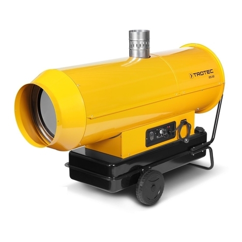
Trotec IDS 900 User manual

TRT-BA-IDS900-TC211117TTRT01-001-EN
IDS 900
EN
ORIGINAL INSTRUCTIONS
OIL HEATER

2 EN
oil heater IDS 900
Table of contents
Notes regarding the instructions ..........................................2
Safety .....................................................................................2
Information about the device................................................6
Transport and storage...........................................................7
Assembly and start-up..........................................................8
Operation .............................................................................12
Available accessories .........................................................16
Errors and faults..................................................................17
Maintenance ........................................................................20
Technical annex...................................................................23
Disposal ...............................................................................27
Declaration of conformity ...................................................27
Notes regarding the instructions
Symbols
Danger
This symbol indicates dangers to the life and health of
persons due to suspended loads.
Warning of electrical voltage
This symbol indicates dangers to the life and health of
persons due to electrical voltage.
Warning of flammable substances
This symbol indicates dangers to the life and health of
persons due to flammable substances.
Warning of hot surface
This symbol indicates dangers to the life and health of
persons due to hot surface.
Warning
This signal word indicates a hazard with an average
risk level which, if not avoided, can result in serious
injury or death.
Caution
This signal word indicates a hazard with a low risk
level which, if not avoided, can result in minor or
moderate injury.
Note
This signal word indicates important information (e.g.
material damage), but does not indicate hazards.
Info
Information marked with this symbol helps you to carry
out your tasks quickly and safely.
Follow the manual
Information marked with this symbol indicates that the
instructions must be observed.
These instructions are only valid with the supplier's instructions
for the burner (Ecoflam).
You can download the current version of the instructions via the
following link:
IDS 900
https://hub.trotec.com/?id=42920
Safety
Read this manual carefully before starting or using the
device. Always store the manual in the immediate vicinity
of the device or its site of use.
Warning
Read all safety warnings and all instructions.
Failure to follow the warnings and instructions may
result in electric shock, fire and/or serious injury.
Save all warnings and instructions for future
reference.
This device must not be used by children and persons
under16years of age.
Children shall not play with the appliance. Cleaning and
user maintenance shall not be made by children
under16years.
Warning
Do not use the device in rooms if persons are present
who cannot leave the room independently and who are
not under constant supervision.
• Do not use the device in potentially explosive rooms or
areas and do not install it there.
• Do not use the device in aggressive atmosphere.
• Only put up the device in an upright, stable position on firm
ground.
• Let the device dry out after a wet clean. Do not operate it
when wet.

EN 3
oil heater IDS 900
• Do not use the device with wet or damp hands.
• Do not expose the device to directly squirting water.
• Never insert any objects or limbs into the device.
• Do not cover the device during operation.
• Do not remove any safety signs, stickers or labels from the
device. Keep all safety signs, stickers and labels in legible
condition.
• Attention: In Germany, the Federal Emission Protection
Directive applies. Do not operate the device for more than
3months at the same place. Prior to planning the flue gas
system, gather information about the national legislation
and contact a responsible specialist.
• Do not sit on the device.
• This appliance is not a toy. Keep away from children and
animals. Do not leave the device unattended during
operation.
• Check accessories and connection parts for possible
damage prior to every use of the device. Do not use any
defective devices or device parts.
• Ensure that all electric cables outside of the device are
protected from damage (e.g. caused by animals). Never
use the device if electric cables or the power connection
are damaged!
• The mains connection must correspond to the
specifications in the Technical annex.
• Insert the mains plug into a properly fused mains socket.
• Observe the device's power input, cable length and
intended use when selecting extensions to the power
cable. Completely unroll extension cables. Avoid electrical
overload.
• Before carrying out maintenance, care or repair work on
the device, remove the mains plug from the mains socket.
Hold onto the mains plug while doing so.
• Switch the device off and disconnect the power cable from
the mains socket when the device is not in use.
• Do not under any circumstances use the device if you
detect damages on the mains plug or power cable.
If the power cable is damaged, it must be replaced by the
manufacturer, its service agent or similarly qualified
persons in order to avoid a hazard.
Defective power cables pose a serious health risk!
• When positioning the device, observe the minimum
distances from walls and other objects as well as the
storage and operating conditions specified in the Technical
annex.
• Make sure that the air inlet and outlet are not obstructed.
• Make sure that the suction side is kept free of dirt and
loose objects.
• Do not place the device on combustible ground.
• Only transport the device in an upright position.
• Only use original spare parts, for otherwise safe and
functional operation cannot be ensured.
• Do not store combustible materials near the
device(minimum distance3m).
• Take the necessary fire protection measures.
• Only install the device in roofed outdoor areas or in well-
ventilated indoor spaces with exhaust system.
• Only position the device near flue pipes or electrical supply
control panels that comply with the specified parameters.
• Make sure that the maximum thermal output of the heater
is not exceeded (chapter Technical annex).
• Make sure that the air supply is not below the nominal air
supply. If the air flow rate is insufficient, the combustion
chamber will heat up and the overheating protection
thermostat will switch the device on and off continuously
(see chapter Errors and faults).
• Do not use the heating device together with a
programming device, a timer, a separate remote control
system or any other device that automatically switches the
heating device on, as there is a risk of fire if the heating
device is covered or incorrectly positioned.
Intended use
The device was developed for the purpose of generating hot air
and may only be used in roofed over outdoor areas or in well-
ventilated interior spaces whilst adhering to the technical data.
The device is suited for heating large rooms such as tents,
warehouses, workshops, construction sites, greenhouses or
agricultural halls.
It is intended to be used without frequent site changes.
The device may only be used in rooms with sufficient fresh air
supply and exhaust discharge.
The device must only be operated with diesel (10% biodiesel
maximum) and kerosene, but not with petrol, heavy fuel oil, etc.
Foreseeable misuse
• The device must not be positioned or operated in areas
with a high risk of fires or in potentially explosive
atmospheres.
• Do not place any objects, e.g. clothing, on the device.
• Do not use the device out of doors, unless under a roof.
• The device must not be operated in rooms with an
insufficient combustion air supply.
• Do not make any unauthorised modifications, alterations or
structural changes to the device.
• Do not use this device in the vicinity of fuel, solvents,
varnishes or other easily inflammable vapours or in rooms
where these substances are stored.
• Do not use the device out of doors.
4 EN
oil heater IDS 900
Personnel qualifications
People who use this device must:
• be aware of the dangers resulting from heat, fire hazard
and insufficient ventilation when working with oil heaters.
• be aware of the dangers that occur when handling fuels
such as diesel or kerosene
• have read and understood the instructions, especially the
Safety chapter.
Electrically skilled person
Electrically skilled personnel must be able to read and
understand electric circuit diagrams, to put electrical systems
into service and to maintain them, to wire control cabinets, to
ensure the functionality of electrical components and to identify
possible hazards from electrical and electronic systems.
Professionals with the relevant training, e.g. industrial
mechanics
Professionals are persons who, on the basis of their professional
training, experience and knowledge of the relevant regulations,
have sufficient expertise to be able to assess the work assigned
to them and to recognise potential hazards. They are allowed to
install the device, take it into operation and to perform
maintenance activities.
Instructed person
Instructed persons have been informed of the tasks they were
entrusted with as well as of potential hazards resulting from
inappropriate behaviour. They are allowed to operate and
transport the device and perform simple maintenance activities
(cleaning the housing, cleaning the fan).
The device is to be maintained and looked after by instructed
personnel.
Safety signs and labels on the device
Note
Do not remove any safety signs, stickers or labels from
the device. Keep all safety signs, stickers and labels in
legible condition.
The following safety signs and labels are attached to the device:
Safety instructions
The following safety instructions are provided in German and Russian
on a label on the device:
• Carefully read the instructions before using the air heater.
• Strictly observe the applicable regulations and local laws
regarding installation, maintenance and use of the air heater.
• Do not use the air heater near flammable surfaces or materials.
• Make sure there is sufficient air exchange in the room where
the air heater is used.
• Connect the air heater to an earthed socket.
• Only use diesel fuel of type2 maximum.
• Do not use petrol, waste oil or lubricating oil.
• Do not add fuel while the machine is in operation.
• Do not restart the air heater if excess diesel fuel has
accumulated in the combustion chamber.
• Allow the machine to cool down. Do not pull the plug out of the
socket while the air heater is in operation. Only stop the air
heater with the designated switch on the control panel. The air
heater is automatically shut down as soon as it has cooled
down sufficiently.
• Regularly clean the filter and, if necessary, remove the water
from the container.
• When starting up the device for the first time after it has not
been used for a long time, the switch-on procedure may have to
be repeated several times. In this case wait about 2minutes
prior to start-up.
• Do not make any changes on the air heater. Contact a qualified
customer centre for maintenance interventions.
Disconnect the power supply before carrying out any maintenance
work.
The following safety instructions are provided on a label on the device
in Italian, German, French, English, Spanish and Russian.
This air heater must be installed in accordance with the applicable
regulations and laws and may only be used in sufficiently ventilated
rooms. Read the instructions before installing and using the air
heater.
The nameplate is provided on the device in German and English:
Type: IDS 900
Article no.: 1430000160
Heating capacity: 236kW
Air volume flow: 17000 m³/h
Mains connection: 1/N/PE ~ 230 V/50 Hz
Fuel consumption: 21.69 l/h
Tank content: -I
Fuel: diesel (10% biodiesel maximum) or kerosene

EN 5
oil heater IDS 900
Safety instructions
Noise level: 69 dB(A)
Weight: 351 kg
The following label is attached to the device in English. The label
indicates safety instructions about filling specifications for the tank
and the ambient temperature:
Kerosene fuel can be used at temperatures down to-40°C and at
higher temperatures.
Winter fuel mix can be used at temperatures down to-20°C and at
higher temperatures.
Diesel fuel can be used at temperatures down to0°C and at higher
temperatures.
The following label on the device indicates the electrical connection.
Residual risks
Warning of electrical voltage
Work on the electrical components must only be
carried out by an authorised specialist company!
Warning of electrical voltage
Before any work on the device, remove the mains plug
from the mains socket!
Do not touch the mains plug with wet or damp hands.
Hold onto the mains plug while pulling the power cable
out of the mains socket.
Warning of flammable substances
Handling fuels entails a risk of fire.
Take sufficient precautions when handling fuels such
as diesel or kerosene (10% biodiesel max.)
Do not spill any diesel or kerosene! Do not inhale the
vapours nor swallow any fuel! Avoid skin contact!
Warning of hot surface
Parts of the device, especially at the air outlet, become
very hot during operation. There is a danger of burning
and fire. Do not touch the device during operation!
During operation observe a safety distance of at least 3
m to the device front! Observe the minimum distance
from walls or other objects according to the technical
data!
Warning of hot surface
Parts of this appliance can become very hot and cause
burns. Particular attention is to be paid when there are
children or vulnerable persons present!
Warning of hot surface
Improper handling entails a risk of burning. Only use
the device as intended!
Warning
Dangers can occur at the device when it is used by
untrained people in an unprofessional or improper way!
Observe the personnel qualifications!
Warning
The device is not a toy and does not belong in the
hands of children.
Warning
Risk of death due to suspended loads!
Make sure that nobody is situated in the immediate
proximity.
Warning
Risk of suffocation!
Do not leave the packaging lying around. Children may
use it as a dangerous toy.

6 EN
oil heater IDS 900
Warning
Improper installation entails a risk of fire.
Do not place the device on combustible ground.
Do not place the device on high-pile carpets.
Warning
The device must not be covered, there is an imminent
fire hazard!
Behaviour in the event of an emergency
1. In case of an emergency, immediately extinguish the pilot
flame by setting the Heating/ventilation switch to
position0.
2. In an emergency, disconnect the device from the mains
feed-in: Switch the device off and disconnect it from the
mains.
3. Remove persons from the danger area.
4. Do not reconnect a defective device to the mains.
Overheating protection
The device is provided with a safety thermostat which is
activated by overheating of the device (when exceeding the
operating temperature).
If the safety thermostat does not switch in the event of
overheating, the overheating protection will be tripped. The
indicator light of the overheating protectionL2(19) is
illuminated in red. In that case the device switches off
completely and will not switch on again. If so, please contact
the customer service to have the overheating protection
replaced.
Information about the device
Device description
The indirectly fired oil heater serves to heat room air to achieve
faster heating of large rooms.
The device is to be operated exclusively with kerosene or diesel
fuel (10% biodiesel maximum) with the following specifications:
10,200 kcal/kg, max. viscosity1.5°E at 20°C.
It is an device with indirect combustion to be installed in roofed
outdoor areas or in rooms with a sufficient fresh air supply.
The device is equipped with an exhaust gas connection for the
discharge of exhaust gases via the chimney.
The oil heater is further equipped with a fuel filter, a fuel pump
and a hot air outlet duct. The end piece of the hot air outlet duct
can be replaced by ducts with2 or4openings. All openings are
to be kept open.
THIS HEATER IS FOR PROFESSIONAL USE. IT HAS BEEN
CAREFULLY DESIGNED FOR MOBILE AND TEMPORARY
PROFESSIONAL APPLICATIONS. IT HAS NOT BEEN DESIGNED
FOR DOMESTIC USE NOR FOR COMFORT HEATING AND
SHOULD NEVER BE USED TO HEAT CLOSED ROOMS WITHOUT
ADEQUATE VENTILATION.
Functional principle
The device generates warmth by preparing the sucked-in, cold
air at the enlarged area of the combustion chamber, the heat
exchanger. The burner of the device sucks in the required
combustion air from the outside via air inlet nozzles or from the
room to be heated. If the air is sucked in from the room to be
heated, the room must be sufficiently ventilated. The air to be
heated is completely isolated from the combustion chamber,
where the fuel is burned. The combustion products are
discharged into the open air through a flue pipe. The sucked-in
air is heated and fed back to the environment via the air outlet.
1

EN 7
oil heater IDS 900
Device depiction
2
1
11
3
4
5
6
79
8
10
12
No. Designation
1Air outlet
2Stop bolt
3Flue pipe connection
4Control box
5Cooling fan
6Protective bar
7Wheel
8Thermostat housing
9Foot
10 Burner housing
11 Transport handle
12 Tank connection with cover
Transport and storage
Note
If you store or transport the device improperly, the
device may be damaged.
Note the information regarding transport and storage of
the device.
Transport
To make the device easier to transport, it is fitted with a
transport handle and two wheels.
Before transporting the device, observe the following:
• Switch the device off.
• Hold onto the mains plug while pulling the power cable out
of the mains socket.
• Do not use the power cable to drag the device.
• Hold the front handles when repositioning or transporting
the device. The heater will move on its rear wheels.
• Allow the device to cool down sufficiently.
Storage
Before storing the device, proceed as follows:
• Switch off the device.
• Hold onto the mains plug while pulling the power cable out
of the mains socket.
• Allow the device to cool down sufficiently.
When the device is not being used, observe the following
storage conditions:
• dry and protected from frost and heat
• in an upright position where it is protected from dust and
direct sunlight
• with a cover to protect it from invasive dust, if necessary

8 EN
oil heater IDS 900
Assembly and start-up
Scope of delivery
• 1x device
• 1x manual
• 1xhose connector, Ø700mm
• 1xconnection kit for an external oil tank
Unpacking the device
1. Open the cardboard box and take the device out.
2. Completely remove the packaging.
3. Fully unwind the power cable. Make sure that the power
cable is not damaged and that you do not damage it during
unwinding.
Assembly
Upon delivery the device is partially preassembled. The electric
switch panel, burner, fan thermostat, overheating thermostat
and safety thermostat with manual restart are already
connected.
Power connection and settings prior to assembly
1. Check the connection to the power supply before
commissioning the air heater.
ðMake sure that the values of the power supply network
correspond to the specifications on the identification
plate.
2. Then connect the power cable to a properly secured
socket. On construction sites, there must be an RCD
upstream of the socket according to VDE0100/0105.
Floor installation and ceiling mounting
Danger
Suspended loads!
Risk of death due to falling loads.
The air heater can be mounted as follows:
• on the floor in a stable position
• suspended from the ceiling using ropes and/or chains with
a suitable size and length fastened to the four suspension
points
The minimum distance to walls, to the floor and/ or to the
ceiling must be at least 2m.
max. 5°

EN 9
oil heater IDS 900
Connection to the hot air feed ducts
The hot air distributor is designed for operation with direct air
distribution.
The hot air opening can be replaced with a 2-way or 4-way
distributor head in order to divide the hot air flow by means of
flexible channel modification.
1. Disassemble the original outlet nozzle.
2. Replace the original outlet nozzle with the 2-way or 4-way
distributor head.
In individual cases, the devices can also be connected to ducts
with the corresponding diameter.
Have the following checks and rectifications carried out by a
qualified electrician if the fixtures are connected to ducts of the
corresponding diameter or if significant changes have been
made to the hot air distribution circuit (e.g. changing the length
or diameter of the pipes and number or curves):
• The power requirement of the air motor must be checked.
It must not exceed the specified value.
• It must be checked whether the air flow rate corresponds
to the nominal flow rate.
Connection to the fuel supply
Always observe the installation, adjustment and operating
regulations stipulated by the local and/or national laws
regarding the use of air heaters.
The following is to be observed for positioning:
• Before planning the exhaust system, inform the
responsible chimney sweep according to DIN18160.
• Have the device installed by an expert technician.
• Have the exhaust emission of the burner checked at
regular intervals.
• Risk of injury due to poisoning.
• Improper installation causes health problems.
In order to connect the device to the fuel oil pipe, the fuel oil
tank is to be connected to the fuel pump:
• directly using the fuel oil pump of the burner
Observe the dimensions and lengths specified in the
burner's operating manual.
• indirectly using an auxiliary pump for the fuel oil
Contact the customer service for a proper dimensioning of
the system.
Connection to the smoke outlet duct
The smoke outlet ducts must be made of steel in accordance
with EN1443.
The combustion efficiency and the proper burner operation
depend on the chimney draught. For connection to the chimney
pipe, observe the applicable legal regulations and the following
provisions:
• The chimney connection must be as short as possible and
ascending (minimum height 1m).
• There must be no sharp curves or reductions in cross-
section.
• Always provide a wind shield to prevent the penetration of
water or clogging of the smoke outlet due to wind.
• The draught of the chimney sweep must not be lower than
the nominal value.
• Every air heater must have its own chimney.
Info
The use of concentric pipes for smoke outlet or intake
of combustion air is expressly prohibited for this
device. It can severely and permanently affect their
functioning.
Position for the flue pipe
a
b

10 EN
oil heater IDS 900
e
d
c
a
No. Designation No. Designation
A min. 2m aWall duct with elbow
min.5°
B min. 1m bFlue pipe
C as short as possible cDraught booster H-
shaped
D ≥ Ø 120mm/150mm dFlue pipe connection
E min. 1m eOuter wall
Positioning
A number of spatial and technical conditions have to be
considered for the selection of the device's installation site.
Non-observance may impair the proper functioning of the device
or the accessories or can entail risks of personal injury and
property damage.
The following is to be observed for positioning:
• The device may only be operated on roofed over surfaces.
• Do not operate the device for more than 3months at the
same place. Prior to planning the flue gas system, gather
information about the national legislation and contact a
responsible specialist.
• The device is to be set up in a stable position on
incombustible ground.
• The device must be set up in close proximity to a chimney,
an outer wall or on an open, ventilated surface.
• The device must be connected to a properly secured mains
power socket.
• The room where the device is positioned must be
sufficiently ventilated.
Ensure a sufficient fresh air supply, especially when there
are people or animals in the same room with the device!
• The minimum distance between the wall and the air inlet
opening of the device must be at least2m(see figure).
• The minimum distance between the device and
combustible materials must be at least3m.
• The inlet and outlet openings must not be covered.
• There must be no walls or large objects near the device.
• There must be a sufficient number of fire extinguishers
available.
2 m
2 m
2 m
2 m
2 m

EN 11
oil heater IDS 900
Start-up
The following is to be observed prior to commissioning:
• Check the scope of delivery of your device for
completeness. If the scope of delivery is incomplete,
please contact the Trotec customer service or the
specialist dealer where you purchased the device.
• Check the device and its connection parts for potential
damage.
• Observe the conditions described in the chapter
Positioning.
• Connect the external tank (see Establishing the oil supply).
• Check the device for its proper condition prior to start-up
and at regular intervals during application.
• Check whether the characteristics of the power grid
conform to those on the nameplate.
• Each time before you plug the mains plug into the mains
socket and switch on the device, make sure that the fan is
moving freely.
• Connect the power cable to a properly secured socket. On
construction sites, there must be a residual current
device(RCD) upstream of the socket in accordance with
national regulations (in Germany: VDE0100/0105).
• When starting up the device after it has not been used for
a long time, the switch-on procedure may have to be
repeated several times. In this case wait about 2minutes
prior to start-up.
• The initial start-up must be carried out by a qualified
electrician who verifies whether the combustion
parameters are correct.
Inserting the probe
Note
The initial start-up must be carried out by a qualified
electrician who verifies whether the combustion
parameters are correct.
Note
The burner is preset at the factory. This setting may
deviate from the required setting. It must therefore be
checked and, if necessary, corrected during start-up.
The settings (fuel oil pressure of the burner, combustion head
position, air regulation) can be found in the "Technical Data"
table.
Insert the probe used for regular checks of the combustion and
exhaust gas temperature as follows:
300 mm
The combustion is stable and clean if the combustion
parameters have the following values:
Bacharach index: 0 (white)
CO₂:11/ 12.5%
Oxygen(O₂): 4.5/ 6%
COmax: 500ppm
• Depending on the fuel used and on the installation
conditions (height level, combustion air intake with or
without air inlet etc.), readjustment of the burner may be
required if the combustion parameters are incorrect.
• After completion of the acceptance inspections, seal the
hole for inserting the probe with a material that is heat-
resistant and guarantees tightness of the duct.

12 EN
oil heater IDS 900
Establishing the oil supply
Quick couplings are used to connect the device to an external
tank.
üSwitch the device off according to the Shutdown chapter.
üBefore attempting to connect the external tank, wait until
the device has cooled down completely.
üOnly use fuel suitable for the device (see technical data).
1. Position the device on firm, level and incombustible
ground.
2. Remove the cover from the tank connection of the external
tank.
3. Remove the cover of the device from the tank connection.
4. Attach the feed and return hose to the tank connection of
the external tank using the quick couplings.
5. Attach the feed and return hose to the tank connection of
the device using the quick couplings.
6. Make sure that the hose is firmly attached to avoid
leakage.
7. The device is now connected to the oil supply.
Note
If the tank is empty, the burner flame extinguishes and
the device switches off automatically.
12
Operation
The device may only be used by accordingly instructed persons.
Operating elements
17
36
19
18
20
21
22
23

EN 13
oil heater IDS 900
24
25
26
No.Designation
17 Electrical control box cover
18 Indicator light for thermostat's power supply
19 Safety thermostat indicator light (overheating)
20 Burner indicator light
21 manual reset of the safetythermostat (reset button)
22 Room thermostat socket
23 Connection for oil preheating
24 Burner reset button with lamp
25 Heating/ventilation switch (on/off switch)
26 Operating control lamp
36 Temperature controller with LCD
Control panel
28
37
29
27
31 3033 323435
36
No.Designation Meaning
27 Ubutton Confirms a setting.
28 ▲button If you press the ▲button twice, the
operating time in hours(h) will be
displayed.
The indicated time is not the effective
heating time but the time during
which the device has been supplied
with current and switched on.
If you press the button once, you can
navigate to the previous value.
29 ▼button Navigates to the following value.
30 Pbutton Press and hold, then the editing
mode is displayed.
Press briefly to confirm an entry.
31 +symbol If the red arrow above the+symbol
lights up, the temperature is above
the set value.
32 =symbol If the green LED above the =symbol
lights up, the temperature
corresponds to the set nominal value.
33 -symbol If the red arrow above the-symbol
lights up, the temperature is below
the set value.
34 Out2LED Indicates the operating condition of
the burner thermostat.
35 Out1LED Is illuminated when the fan is
switched on.
36 Temperature
controller with
LCD
Records the outlet temperature and
the operating hours.
Control of the trigger temperature of
the burner thermostat and fan
thermostat.
37 Display Indicates the measured temperature
in°C.

14 EN
oil heater IDS 900
Switching the device on
The device has the following operating modes:
• In operating mode0, the burner is switched off.
• In operating modeV, only the fan operates.
• In operating modeV+H, the fan operates continuously and
the burner runs until the predefined room temperature is
reached.
• In operating modeH, the burner is switched on. The fan,
on the other hand, only operates when the combustion
chamber is sufficiently heated. When the predefined room
temperature is reached, the burner switches off. The fan
only continues to run until the combustion chamber has
cooled down completely.
In general, the device continues to operate until the desired
room temperature is reached.
1. Lift the panel(17) of the control box.
2. Make sure that the Heating/ventilation switch(25) is set to
operating mode0.
25
3. Turn the air heater to operating modeV using the Heating/
ventilation switch(25).
25
ðThe green power operating control lamp(26) lights up.
25
26
ðThe fan(5) is switched on.
4. Then turn the switch(25) to operating modeH orV+H.
25
ðThe burner starts the start-up and pre-purging cycle and
the flame is ignited. After the combustion chamber has
been preheated for several minutes, the main fan switches
on.
Observe the following:
• In case of a failure of the air during start-up or operation,
please refer to the "Errors and faults" chapter to find the
cause for the malfunction.
• After a safety shutdown of the burner, the lamp of the
burner reset button(24) lights up. Press the burner reset
button(24) for three seconds to restart the air heater.
24
• After a safety shutdown of the thermostats, the safety
thermostat indicator light(overheating)(19) lights up. The
indicator light(19) is located on the side of the burner
housing.
18
19
20
• Press the manual reset of the safety thermostat(21) to
restart the air heater.

EN 15
oil heater IDS 900
21
• Never carry out more than two consecutive restarts:
Unburned fuel oil can accumulate in the combustion
chamber and might suddenly ignite during the subsequent
restart.
Ventilation
If you want to use the air heater for continuous ventilation only,
set the Heating/ventilation switch(25) to operating modeV.
Temperature controller
The air heater is equipped with a temperature controller(g) with
LCdisplay(36) that can be used to display and control the
following parameters:
• Detection of the air outlet temperature
• Recording of the operating hours
• Control of the trigger temperature of the fan thermostat
• Control of the trigger temperature of the burner thermostat
28
37
29
27
31 3033 323435
36
Proceed as follows to reset the counter:
1. Turn the Heating/ventilation switch(25) of the device to
operating mode0(OFF).
2. Press and hold theP button(30) of the temperature
controller for at least three seconds.
ðThe word "PASS" flashes for five seconds.
3. Enter the code"-481" by pressing the▼button(29)
several times until the desired indication appears. Press
the Pbutton(30) to confirm and to move to the next
indication.
4. Then press the Ubutton(27).
ðThe air outlet temperature is displayed again.
Control of the trigger temperature of the fan thermostat
The temperature controller is programmed in a way that it
automatically switches the main fan on or off depending on the
temperature set for the combustion chamber. This prevents cold
air from being blown out when the burner starts and the
combustion chamber is not yet sufficiently heated.
This ensures that the internal residual heat is discharged upon
switch-off.
The default temperature setting is35°C with a hysteresis
of5°C.
Operating condition of the fan thermostat
• LED "OUT1"(35) is illuminated in red: the fan is switched
on.
• LED "OUT1"(35) is not Illuminated: the fan is switched
off.
Control of the trigger temperature of the burner thermostat
The temperature controller is programmed in a way that it
automatically switches the burner on or off depending on the
maximum temperature set for the combustion chamber. This
prevents overheating of the combustion chamber so that the
safety thermostatL2 is not triggered. If the safety thermostat
was triggered, the device would be switched off (see also
chapter "Errors and faults").
The default thermostat setting for the maximum temperature of
the combustion chamber is95°C with a hysteresis of5°C.
The "OUT2"LED(34) indicates the operating condition of the
burner thermostat: The LED sequence"-"(33), "="(32) and
"+"(31) indicates the current temperature:
• If the red arrow above the"-"(33) symbol lights up, the
temperature is below the set value. The burner is activated
by the thermostat.
• If the greenLED above the "="(32)symbol lights up, the
temperature corresponds to the set nominal value.
• If the red arrow above the"+"(31)symbol lights up, the
temperature is above the set value. The burner is locked
by the thermostat.
The trigger temperature of the fan thermostat and the burner
thermostat can only be modified after consultation with the
Trotec customer service.

16 EN
oil heater IDS 900
Shutdown
Warning of electrical voltage
Do not touch the mains plug with wet or damp hands.
Note
Damage to the device due to overheating!
Never switch off the device by pulling the mains plug.
This may lead to overheating!
Switch off the device properly. Only remove the mains
plug from the device once the fan motor has stopped
completely.
1. Set the Heating/ventilation switch(25) to 0.
25
ðThe burner stops (burner indicator light(20) goes out) while
the fan is in operation. The fan switches on and off several
times until the combustion chamber has cooled down
completely.
Observe the following:
• Never pull the plug out of the supply control panel to stop
the operation of the air heater. The electrical supply may
only be interrupted after the fan has come to a standstill.
Disconnecting the oil supply
Proceed as follows to disconnect the oil supply:
üMake sure that there is no fuel residue in the feed and
return hose.
üSwitch the device off according to the Shutdown chapter.
üAllow the device to cool down completely.
1. Remove the feed and return hose from the tank connection
of the external tank.
2. Remove the feed and return hose from the tank
connection(12) of the device.
12
3. Reattach the cover of the external tank to the tank
connection of the tank.
4. Reattach the cover of the device to the tank
connection(12) of the device.
Available accessories
Designation Article number
Two-way hose distributor
2 × Ø 600 mm
6100006174
Four-way hose distributor
4 × Ø 400 mm
6100006175
Thermostat with 10m cable 6100007016
Oil pre-heating 6100006177
Filler neck oil filter 6100006161
Oil tank pedestal IDS900, capacity
208litres
6100006176
Exhaust gas pipe rigid, length 1m 6100006214
90° arc connection for exhaust gas pipe 6100006220
Exhaust gas pipe rain cover 6100006226
Air hose Tronect SP-C³, length 7.6m 6100001273

EN 17
oil heater IDS 900
Errors and faults
Warning of electrical voltage
Tasks which require the device to be opened must
only be carried out by authorised specialist
companies or by Trotec.
Warning
Risk of injury due to improper repair!
Never try to make any modifications or repairs on the
device.
Unauthorised modifications can lead to serious injuries
or death.
Have a certified specialist workshop perform the repair
work.
The device has been checked for proper functioning several
times during production. If malfunctions occur nonetheless,
check the device according to the following list.
The device does not start:
• Check the power connection.
• Check the power cable and mains plug for damage. If you
notice damages, do not try to take the device back into
operation.
If the supply cord is damaged, it must be replaced by the
manufacturer, its service agent or similarly qualified
persons in order to avoid a hazard.
• Check the on-site fusing.
Note
Wait for at least 10minutes after maintenance and
repair work. Only then switch the device back on.
The device still does not operate correctly after these
checks:
Please contact the customer service. If necessary, bring the
device to an authorised specialist electrical company or to
Trotec for repair.
Error codes
The following error messages can be displayed on the segment
display:
•Fault on the control box
The red block signal lights up if the safety
thermostatL2(19) is triggered: Press the burner reset
button(24). The reset button and the lamp(24) are located
inside the burner housing. Slide the cover of the reset
button to the side to access the reset button from the
outside.
•Fault on the burner
The burner indicator light(20) lights up as a result of the
burner flame monitoring being triggered. In the event of a
safety shutdown, never carry out two consecutive restarts.
Unburned fuels can accumulate in the combustion
chamber and might suddenly ignite during the subsequent
restart.
•Inspections and measures do not produce any results:
Contact the Trotec customer service.

18 EN
oil heater IDS 900
Malfunction Meaning Remedy
Device does not start/device switches off No power supply Check the functioning and position of the
Heating/ventilation switch(25)
Check the characteristics of the
electrical line
Check whether the fuses are intact
Heating/ventilation switch(25) is not set
to the correct position
Set to the correct position
Room thermostat operates irregularly Check and correct the thermostat
position
Check whether the thermostat is
operational
The safety system (burner, thermostat
L2, thermal relay of the fan) was not
reset after repair
Please proceed as follows:
• Press the burner reset button(24)
• Press the burner button (button on
control system)
• Press the button for the safety
thermostat with manual reset(21)
• Press the thermal relay of the fan
Tripping of thermostat L1 Overheating of the combustion chamber Check fuel supply
Check the correct positioning of flaps,
supportsetc.
Remove dirt/foreign objects from the air
ducts and ventilation grilles
Tripping of thermostat L2 (warning
light(19) lights up)
Overheating of the combustion chamber Check fuel supply
Check the correct positioning of flaps,
supportsetc.
Remove dirt/foreign objects from the air
ducts and ventilation grilles
Tripping of thermal relay RM (lamp(18)
lights up)
Overheating of the combustion chamber Heater with axial fan: Remove any
obstacles from the air inlet. Reduce the
lengths of the air ducts
Heater with centrifugal fan: Check the
fan belt setting
In any case, check that the power
consumption of the air motor is lower
than the value indicated on the
nameplate
The burner starts, the flame does not
ignite and the reset indicator and the
control system is illuminated
Irregular operation of the burner Should this situation reoccur after
pressing the burner reset button(24)
and after restarting the device, please
contact the technical customer service.

EN 19
oil heater IDS 900
The fan does not start or starts with a
delay
No power supply Check whether the fuses are intact
Check the electrical connections
Thermostat(21) damaged Check, adjust or exchange the
thermostat
Motor winding burnt or interrupted Exchange fan and motor
Motor capacitor burnt (Mod. "M") Exchange capacitor
Motor bearing blocked Exchange bearing
The fan makes noises or vibrates Foreign object on air inlet Remove foreign objects and dirt
Insufficient air circulation Remove foreign objects and dirt
Insufficient heating Insufficient heat output of the burner Please contact the technical customer
service.

20 EN
oil heater IDS 900
Maintenance Maintenance intervals
Maintenance and care interval before every
start-up
as needed at least every
2weeks
at least every
4weeks
at least every
6months
at least
annually
Check air inlets and outlets for dirt and foreign
objects and clean ifnecessary
X
Check air inlet grid(s) for dirt and foreign objects
and clean ifnecessary
X X
Clean the exterior X X
Visually check the inside of the device for dirt X X
Check for damage X
Check attachment screws X X
Check the thermostats x
Check the electrical connections x
Clean the motor and fan x x
Checking and testing the burner x x
Clean combustion chamber x x
Check fuel oil supply line x
Check the air heater x
Clean heat exchanger x x
Clean the interior x
Test run X
Other manuals for IDS 900
1
Table of contents
Other Trotec Heater manuals

Trotec
Trotec IDX 20 D User manual

Trotec
Trotec IDE 20 User manual

Trotec
Trotec IDS 20D User manual

Trotec
Trotec TFC 25 E User manual

Trotec
Trotec TFC 220 E User manual

Trotec
Trotec TES 200 User manual

Trotec
Trotec TIH 300 S User manual

Trotec
Trotec TDE 25 User manual

Trotec
Trotec IDE 20 D User manual

Trotec
Trotec TCH 20 E User manual

Trotec
Trotec IRD 1200 Instruction Manual

Trotec
Trotec TFC 16 E User manual

Trotec
Trotec TRH 27 E User manual

Trotec
Trotec IDS 30 F User manual

Trotec
Trotec IR 2400 User manual

Trotec
Trotec TRH 25 E User manual

Trotec
Trotec IDS 100 User manual

Trotec
Trotec TDS 50 User manual

Trotec
Trotec TRH 28 E User manual

Trotec
Trotec TFC 13 E User manual