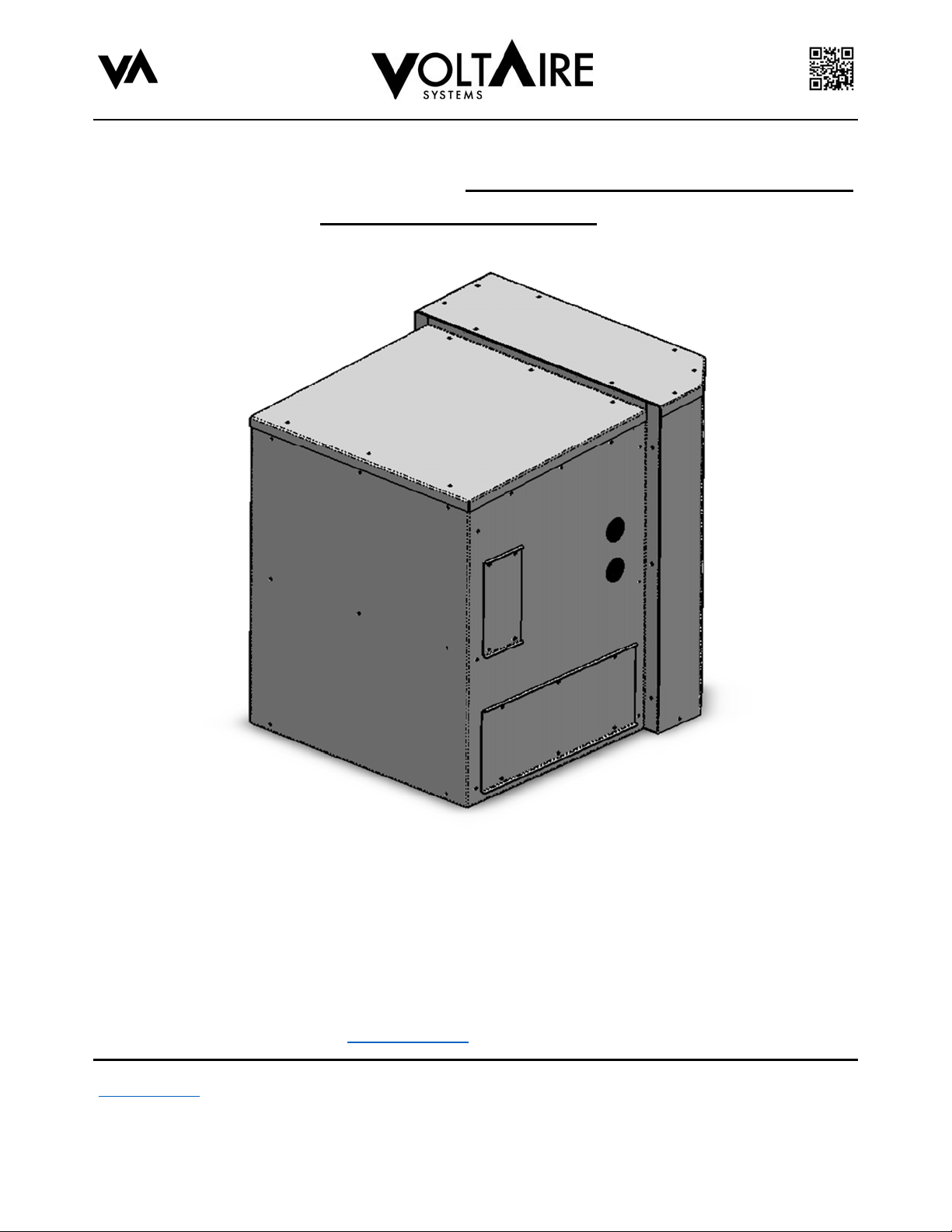
Pressurization Module with
Plenum Installation, Operation
and Maintenance Manual
VoltAire Systems, LLC
Specifications are subject to change without notice
Page 3 of 20
VoltAire Doc. # DA0322A
Published: June 13, 2023
1. IMPORTANT INFORMATION TO REVIEW PRIOR TO INSTALLATION,
OPERATION AND MAINTENANCE
READ THE ENTIRE MANUAL PRIOR TO INSTALLING, OPERATING AND MAINTAINING the VoltAire Systems
Pressurization Module. Do not install or perform maintenance on the equipment if you do not understand all of the
instructions. Contact VoltAire Systems at (407) 378-7482 with any questions or concerns.
The pressurization module should be fully inspected on initial delivery. Open the packaging completely at the time of
initial delivery and verify there is no hidden or concealed damage. Shipping damage, including concealed damage, is
not covered under warranty. Reject the shipment if any damageis found.
WARNING: IMPROPER INSTALLATION AND OPERATION MAY CAUSE PROPERTY DAMAGE, PERSONAL
INJURY OR LOSS OF LIFE. The pressurization module shall only be installed andserviced by a certified professional in
strict accordance with the requirements within this manual,in accordance with all local/state/federal codes, and per
industry standards. Remove power from the unit during maintenanceand installation, as linevoltage may be dangerous,
hazardous and lethal.
In the event of a conflict, code requirements shall take precedence over the instructions provided within this manual. The
installer shall be aware of allcode requirements and shall comply fully.
Use care when transporting and lifting the pressurization module.
WARNING: WEAR PROPER PERSONAL PROTECTION EQUIPMENT, INCLUDING BUT NOT LIMITED TO SAFETY
GLASSES, GOGGLES, AND GLOVES. EDGES MAY BE SHARP.
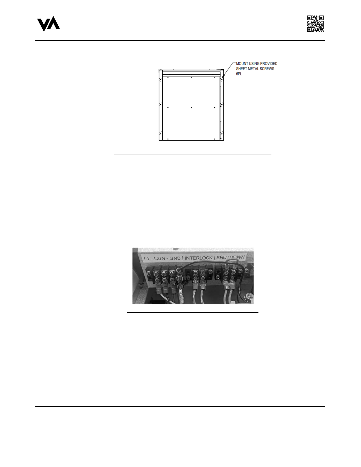
A field provided disconnect must be provided by the installer with the power supply circuit serving thepressurization
module. The installer shall size the electrical wire and disconnect in accordance with all applicable codes. Verify wire
terminals and voltageprior to starting the pressurization module, otherwise you may damage the electrical components.
These instructions should be retained by the owner and/or with the unit.
2. PARTS SHIPPED LOOSE AND TOOLS/MATERIALS PROVIDED BY THE
INSTALLER
Materials shipped loose in addition to this manual are as follows:
a) Ship Loose Kit
DESCRIPTION PART NUMBER
Pressurization Module Ship Loose Kit D0Z0007VAA
Pressurization Module Plenum Ship Loose Kit D0Z0008VAA
b) Bard Economizer Exhaust Modification Kit (Optional, Sold Separately)
DESCRIPTION PART NUMBER
W18-W24 Economizer Exhaust Mod
Field Kit
Bard Models W18-W24
W18-W24ECONMODKIT
W30-W36 Economizer Exhaust Mod
Field Kit (Bard Models W18-W24) W30-W36ECONMODKIT