Voltaire 4036 (QDR) User manual

Grid Director
4036 (QDR) / 2036 (DDR)
August 2010
Doc P/N: DOC-00467
Doc Rev: A09

VOLTAIRE, INC. AND ITS AFFILIATES (“VOLTAIRE”) FURNISH THIS DOCUMENT “AS IS,” WITHOUT WARRANTY OF
ANY KIND. VOLTAIRE DISCLAIMS ALL WARRANTIES, EXPRESS OR IMPLIED, INCLUDING, WITHOUT LIMITATION,
THE IMPLIED WARRANTIES OF MERCHANTABILITY, FITNESS FOR A PARTICULAR PURPOSE, NON-
INFRINGEMENT AND THOSE ARISING FROM A COURSE OF PERFORMANCE, A COURSE OF DEALING, OR TRADE
USAGE. VOLTAIRE SHALL NOT BE LIABLE FOR ANY ERROR, OMISSION, DEFECT, DEFICIENCY OR
NONCONFORMITY IN THIS DOCUMENT AND DISCLAIMS ALL LIABILITY, INCLUDING LIABILITY FOR INFRINGEMENT
OF ANY INTELLECTUAL PROPERTY RIGHTS RELATED TO THE INFORMATION CONTAINED IN THIS DOCUMENT.
No license, expressed or implied, to any intellectual property rights is granted under this document. This document, as well
as the software described in it, are furnished under a separate license and shall only be used or copied in accordance with
the terms of the applicable license. The information in this document is furnished for informational use only, is subject to
change without notice, and should not be construed as any commitment by Voltaire. Except as permitted by the applicable
license, no part of this document may be reproduced, stored in a retrieval system, or transmitted in any form or by any
means without the express written consent of Voltaire.
Names and logos identifying products of Voltaire in this document are registered trademarks or trademarks of Voltaire. All
other trademarks mentioned in this document are the property of their respective owners.
Copyright © 2010 Voltaire, Inc. All rights reserved.
Voltaire Doc P/N: DOC-00467
Business Headquarters
Voltaire Inc.
100 Apollo Drive
Chelmsford, MA 01824
USA 01821
Tel: 978-439-5400
Fax: 978-439-5401
R&D Center
Voltaire Ltd.
13 Zarchin St
Raanana 43662
Israel
Tel: +972-74-7129000
Fax: +972-74-7129111

Contents
Contents ............................................................................................................................................... iii
Figures ................................................................................................................................................ v
Tables ............................................................................................................................................... vi
About this Manual..................................................................................................................................... vii
Chapter 1. Introduction ..........................................................................................................................1
4036/2036 Switch Overview...............................................................................................................2
4036/2036 Switch Main Features.......................................................................................................3
Management ......................................................................................................................................4
Chapter 2. Unpacking.............................................................................................................................5
Overview ............................................................................................................................................6
Package Contents..............................................................................................................................6
Unpacking the 4036/2036 Switch.......................................................................................................7
Rail Kit (KIT-00008)............................................................................................................................9
Multipurpose (Mng) Console Cable Kit ............................................................................................10
Packing the 4036/2036 Switch.........................................................................................................10
Chapter 3. Getting Started ...................................................................................................................12
Overview ..........................................................................................................................................13
Front Panel Description....................................................................................................................13
Rear Panel Description ....................................................................................................................15
Chapter 4. Product Options.................................................................................................................17
4036/2036 Switch Available Configurations.....................................................................................18
InfiniBand Clusters Using the 4036/2036 Switch.............................................................................18
Ordering Information ........................................................................................................................20
Chapter 5. Technical Specifications and Certifications....................................................................22
4036/2036 Switch Technical Specifications.....................................................................................23
Power Specifications - Power Supply Module .................................................................................24
Certifications.....................................................................................................................................25
Gost-R Certification..........................................................................................................................26
Declarations .....................................................................................................................................26
Declaration of Conformity......................................................................................................26
Hazardous Substances (RoHS 5) Compliance Declaration..................................................27
Label(s) ............................................................................................................................................27
Shock and Vibration.........................................................................................................................28
Chassis Clearance Requirements....................................................................................................28
Weights and Dimensions .................................................................................................................29
Acoustic Data...................................................................................................................................29

Contents
Doc P/N DOC-00467 A09
4036/2036 Installation Manual Page iv
Export Information............................................................................................................................30
Shipping Restrictions........................................................................................................................30
Chapter 6. Hardware Installation.........................................................................................................31
Overview ..........................................................................................................................................32
Installation Options...........................................................................................................................32
Cooling...................................................................................................................................32
Required Tools.................................................................................................................................33
Site Planning....................................................................................................................................33
Rack and Clearance Requirements ......................................................................................33
Site Environment Specification..............................................................................................34
Power Requirements.............................................................................................................34
Site Preparation Checklist.....................................................................................................34
Measuring the Distance between Mounting Rails............................................................................35
Assembling and Mounting the Rail...................................................................................................35
Rail Kit35
Option 1.................................................................................................................................37
Option 2.................................................................................................................................43
4036/2036 Switch Power Up............................................................................................................48
Field Replaceable Units ...................................................................................................................48
Fan Unit.................................................................................................................................48
Power Supplies......................................................................................................................49
Chapter 7. Cabling ................................................................................................................................51
Overview ..........................................................................................................................................52
Cabling Guide Bracket Installation...................................................................................................52
InfiniBand Cabling - QDR.................................................................................................................55
Multipurpose Management (Mng) Console Cable ...........................................................................56
Chapter 8. Operation ............................................................................................................................58
Overview ..........................................................................................................................................59
Powering on the 4036/2036 Switch..................................................................................................59
4036/2036 Switch LED Indicators....................................................................................................60
Where to Go Next.............................................................................................................................61
Chapter 9. Troubleshooting.................................................................................................................62
Overview ..........................................................................................................................................63
Solving Startup Problems.................................................................................................................63
Preparation before Contacting Customer Service ...........................................................................64
Appendix A Option 3 – Chassis Installation in an iDataPlex Rack ....................................................65
Unpacking the 4036/2036 Switch.....................................................................................................65
Mounting the iDataplex Kit...............................................................................................................67
Appendix B Cabling Information ...........................................................................................................72
IB Port Cable Specifications.............................................................................................................72
1 GbE Ports (Management).............................................................................................................73
Appendix C QSFP Cable.........................................................................................................................74

Figures
Figure 1-1. 4036/2036 Front View ................................................................................................................2
Figure 1-2. 4036/2036 Rear View.................................................................................................................3
Figure 2-1. 4036/2036 Cardboard Package (Open) - Standard ...................................................................7
Figure 2-2. Removing the 4036/2036 Switch from the Cardboard Package................................................8
Figure 2-3. Fixed Rail (KIT-00008) ...............................................................................................................9
Figure 2-4. Console Cable Kit (Mng) ..........................................................................................................10
Figure 2-5. Packing the 4036/2036 Switch.................................................................................................11
Figure 3-1. 4036/2036 Front Panel.............................................................................................................13
Figure 3-2. 4036/2036 Rear Panel..............................................................................................................15
Figure 4-1. InfiniBand Cluster Using 4036 Switch Single-hop Configuration .............................................18
Figure 4-2. InfiniBand Cluster Using 2036 Switch Single-hop Configuration .............................................18
Figure 4-3. InfiniBand Cluster Using 4036/2036 Switch Triple-hop Configuration .....................................19
Figure 4-4. InfiniBand Cluster Using 4036/2036 Switch Three-hop Configuration.....................................19
Figure 5-1. 4036 Label (Example) ..............................................................................................................27
Figure 5-2. 2036 Label (Example) ..............................................................................................................28
Figure 6-1. 4036/2036 – Option 1 Assembly ..............................................................................................38
Figure 6-2. Mounting the long bracket........................................................................................................39
Figure 6-3. Positioning and aligning the mounting bar and long bracket....................................................39
Figure 6-4. Securing the mounting bar .......................................................................................................39
Figure 6-5. Installing the clip nuts and placing the power cord...................................................................40
Figure 6-6. Inserting the switch into the rack..............................................................................................40
Figure 6-7. Power cord over the long bracket.............................................................................................40
Figure 6-8. Securing power cords...............................................................................................................41
Figure 6-9. Connecting the power cables...................................................................................................41
Figure 6-10. Secure the long brackets to the rack rail................................................................................41
Figure 6-11. Mounting the short bracket.....................................................................................................42
Figure 6-12. Adjusting the short bracket.....................................................................................................42
Figure 6-13. Securing Screws and Brackets...............................................................................................42
Figure 6-14. Switch mounted in a rack – Rack rear view ...........................................................................43
Figure 6-15. Switch mounted in a rack – Rack front view...........................................................................43
Figure 6-16. 4036/2036 – Option 2 Assembly ............................................................................................44
Figure 6-17. Mounting the short bracket.....................................................................................................45
Figure 6-18. Mounting the long bracket......................................................................................................45
Figure 6-19. Positioning and aligning the mounting bar and long bracket..................................................45
Figure 6-20. Securing the rail......................................................................................................................46
Figure 6-21. Placing the clip nuts on the vertical rack rails.........................................................................46
Figure 6-22. Insert the switch into the rack.................................................................................................46
Figure 6-23. Secure the rack screws..........................................................................................................46
Figure 6-24. Installing the long bracket.......................................................................................................47
Figure 6-25. Securing the rack screws .......................................................................................................47

Figures
Doc P/N DOC-00467 A09
4036/2036 Installation Manual Page vi
Figure 6-26. Securing the long bracket screws to the mounting bar..........................................................47
Figure 6-27. Switch mounted in a rack – Rack front view...........................................................................47
Figure 6-28. Replacing the Fan ..................................................................................................................48
Figure 6-29. Replacing the Power Supply ..................................................................................................49
Figure 7-1. Cabling Guide Bracket (CG-24)................................................................................................52
Figure 7-2. Installing a Cabling Guide Bracket ...........................................................................................53
Figure 7-3. Installing a Cabling Guide Bracket (sliding rail)........................................................................53
Figure 7-4. Cable Management..................................................................................................................53
Figure 7-5. Cabling......................................................................................................................................54
Figure 7-6. Console Cable Kit (Mng) ..........................................................................................................56
Figure A-1. 4036/2036 Cardboard Package (Open) - Standard.................................................................66
Figure A-2. 4036/2036 – Assembly in an iDataplex Rack ..........................................................................68
Figure A-3. Attaching the mount bracket ....................................................................................................69
Figure A-4. Securing the mount holders.....................................................................................................69
Figure A-5. Securing clip nuts and the mount plates onto the rack............................................................70
Figure A-6. Inserting the mount holder into the mount plate.......................................................................70
Figure A-7. Securing the front of the chassis..............................................................................................71
Tables
Table 3-1. 4036/2036 Front Panel Components........................................................................................14
Table 3-2. Rear Panel Components ..........................................................................................................16
Table 4-1. 4036/2036 Switch Ordering Information...................................................................................20
Table 4-2. 4036/2036 Module Ordering Information..................................................................................20
Table 4-3. 4036/2036 Switch Packing List (According to Configuration)...................................................21
Table 5-1. 4036/2036 Switch Technical Data............................................................................................23
Table 5-2. Power Supply Module Data......................................................................................................24
Table 5-3. Certifications.............................................................................................................................25
Table 5-4. Clearance Requirements..........................................................................................................28
Table 5-5. Unpacked Weights & Dimensions ............................................................................................29
Table 5-6. Packed Weights & Dimensions.................................................................................................29
Table 5-7. Export Information ....................................................................................................................30
Table 6-1. Material and Tools Required.....................................................................................................33
Table 6-2. Site Preparation Checklist ........................................................................................................34
Table 6-3. Rail Kit (P/N KIT-00008) Detailed Part List...............................................................................36
Table 8-1. 4036/2036 Switch LED Indications...........................................................................................60
Table 9-1. iDataplex Mounting Kit (P/N KIT-00004) Part List....................................................................67
Table 10-2. 4X InfiniBand Port Cabling Specifications..............................................................................72

About this Manual
This manual provides installation instructions for the Voltaire high-bandwidth, low-latency
scalable 36-port InfiniBand 4036 QDR and 2036 DDR chassis. It includes the product
specifications, unpacking and installation information, unit power up, and initiation and
troubleshooting procedures.
NOTE:
Refer to the Voltaire release notes for last minute updates and restrictions
Contact Us:
Please send your documentation-related comments and feedback or report mistakes to:
Audience
The manual is intended primarily for system administrators who are authorized to install a
4036 or a 2036 system.
It is assumed that the readers are familiar with the InfiniBand technology and terminology.
Document Conventions
The following lists conventions used in this document.
NOTE: Identifies important information that contains helpful suggestions.
CAUTION: Alerts you to the risk of personal injury, system damage, or loss of data.
WARNING: Warns you that failure to take or avoid a specific action might result in personal
injury or a malfunction of the hardware or software. Be aware of the hazards involved with
electrical circuitry and be familiar with standard practices for preventing accidents before you
work on any equipment.
Text set off in this manner indicates terminal/CLI screen/command
format.

About this Manual
Doc P/N DOC-00467 A09
4036/2036 Installation Manual Page viii
Document Organization
Chapter 1 – Introduction: Brief overview and graphical representation of the switch.
Chapter 2 – Unpacking: Provides a full detail of the package contents and the rai. kit, as
well as step-by-step instructions on how to unpack the 4036/2036.
Chapter 3 – Getting Started: Provides a description of the front and rear panels and of
the product architecture, including a description of the various components.
Chapter 4 – Product Options : Lists the Voltaire 4036/2036 configurations, provides
examples of 4036/2036 in various clusters, and provides the necessary data for ordering
a product configuration, as well as comprehensive technical specifications.
Chapter 5 – Technical Specifications and Certifications: Provides specifications,
certifications, declarations, requirements, weights and dimensions, clearance
information, export information, and shows the label applied on the product’s box,
Chapter 6 – Hardware Installation: Provides detail on how to prepare your site for
installation, preparation and installation of the 4036/2036. It also provides instructions on
how assemble the mounting rails (two options), and replace the Field Replaceable Units.
Chapter 7 – Cabling: Provides information on cabling guide installation, InfiniBand
cabling, including do’s and don’ts, InfiniBand Cable specifications as well as on the
management cable.
Chapter 8 – Operation: Describes how to start up the unit and use the unit indicators.
Chapter 9 – Troubleshooting: Helps you solve startup problems and provides detail on
customer service contacts.
Appendix A – Option 3: Chassis Installation in an iDataPlex Rack.
Appendix B – Cable and Port Pinout: Provides cabling and port pinout information for the
4036/2036.
Appendix C – QSFP Cable: Provides a description of the QSFP cable and connector.
Related Documentation
In addition to this guide, the following product documentation is available:
4036/2036 Getting Started Guide, Voltaire [LIT-00037]
4036/2035 User Manual, Voltaire [DOC-00619]
NOTE:
Please remember to review all product release notes for known issues and limitations.

1
1
Chapter 1. Introduction
This chapter includes the following sections:
4036/2036 Switch Overview......................................................................................................2
4036/2036 Switch Main Features..............................................................................................3

Introduction
Doc P/N DOC-00467 A09
4036/2036 Installation Manual Page 2
4036/2036 Switch Overview
The Voltaire Grid Director 4036/2036 is a high performance, low latency and fully non-
blocking InfiniBand switch for high performance clusters. Delivering 2.88 Tbps of non-
blocking bandwidth with less than 100 nanoseconds of latency (port-to-port), I/O bottlenecks
are removed making applications operate at maximum efficiency.
The 4036/2036 was designed to fit into today’s densely configured racks. It has thirty-six
40Gbps ports that use the new smaller and intelligent QSFP connector in a 1U chassis that is
only 15” deep. The efficient 4036/2036’s smart design makes it is easy to build clusters that
can scale-out into the thousands of nodes.
To meet varying application needs, the 4036 offers Quad Data Rate 4X ports (QDR provides
a date rate of 40, 20 or 10 Gb/s auto-negotiable) while the 2036 offers Dual Data Rate 4X
ports (DDR provides a data rate of 20 or 10 Gb/sec auto-negotiable).
The 4036/2036 switch incorporates redundant, hot-swappable power supplies for High
Availability, as well as a hot-swappable fan unit. The 4036/2036 offers a plug-and-play
environment, allowing servers to be added without taking down the fabric.
The 4036/2036 includes a high-performance CPU for management purposes.
Grid Directors 2036 and 4036 are identical in appearance, distinguishable only by the product
ID label on the chassis.
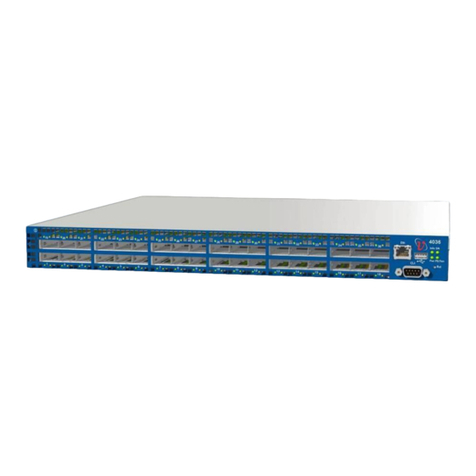
The following figure shows the front view of a 4036 Unit. The front view of the 2036 is
identical.
Figure 1-1. 4036/2036 Front View

Introduction
Doc P/N DOC-00467 A09
4036/2036 Installation Manual Page 3
The following figure shows the rear view of a 4036 Unit. The rear view of the 2036 looks alike.
Figure 1-2. 4036/2036 Rear View
NOTE:
The 2036 and 4036 switches are identical in appearance. Therefore, the graphic
representations are generic and are applicable to either switch.
4036/2036 Switch Main Features
Thirty-Six auto-negotiating QSFP InfiniBand ports in a 1U chassis:
› The 4036 switch is equipped with QDR ports (40 Gbps per port)
› The 2036 switch is equipped with DDR ports (20 Gbps per port)
1Ux19”x15” non blocking standalone switch using a single switch chip
QSFP ports supporting any type of cable, Copper or Optical.
High performance, low power CPU for device management
Ultra low latency under 100 ns (nanoseconds)
Available aggregate bandwidth of up to 2.88 Tbps (QDR), 1440 Gbps (DDR), or 720
Gbps (SDR)
Architected to provide high MTBF
Redundant, hot-swappable power supplies
Front-to-back or back-to-front hot-swappable fan unit.
QSFP InfiniBand ports supporting copper or optical cables and adapters
Built-in cable detection and optimization to achieve the longest available cable distance
and highest performance
Built-in high availability

Introduction
Doc P/N DOC-00467 A09
4036/2036 Installation Manual Page 4
Management
The Grid Director 4036/2036 includes smart device management that provides a simple
interface for deploying, troubleshooting, maintaining and upgrading the switch. With a simple
to use CLI interface, routine tasks such as monitoring the switch’s operation or upgrading
software and firmware are made simple.
The Voltaire Grid Director 4036 comes with an onboard subnet manager, enabling simple,
out-ofthe-box fabric bring-up for small to medium clusters.
Refer to the 4036/2036 User Manual for details on 4036/2036 software requirements and
configuration.

2
2
Chapter 2. Unpacking
This chapter contains the following sections:
Overview....................................................................................................................................6
Package Contents.....................................................................................................................6
Unpacking the 4036/2036 Switch..............................................................................................7
Rail Kit (KIT-00008)...................................................................................................................9
Multipurpose (Mng) Console Cable Kit ...................................................................................10
Packing the 4036/2036 Switch................................................................................................10

Unpacking
Doc P/N DOC-00467 A09
4036/2036 Installation Manual Page 6
Overview
This chapter provides step-by-step instructions for the packing and unpacking of the
4036/2036 switch.
Package Contents
The 4036/2036 switch is supplied in a cardboard box. The switch is delivered with either one
or two pre-installed hot-swappable power supplies (according to configuration) and one hot-
swappable fan unit.
Additional components include:
Two power cords (one per power supply)
Rail kit (see detail in Section 2.4)
A multipurpose console cable kit (Mng)
Voltaire Getting Started Guide (hard copy)
A product CD containing 4036/2036 switch documentation and software
Before unpacking, make sure that the box is sealed and undamaged.
Before beginning the installation of the 4036/2036 switch, verify that the package contains the
items detailed in the packing list.
Check for loose parts or any visible damage to the contents. Notify your supplier if you
detected damaged or missing parts.

Unpacking
Doc P/N DOC-00467 A09
4036/2036 Installation Manual Page 7
Unpacking the 4036/2036 Switch
This section details the 4036/2036 package contents and provides instructions on how to
unpack the chassis.
To unpack the 4036/2036 chassis, perform the following steps:
Step 1 Open the box and check that it contains the items as shown in Figure 2-1.
Figure 2-1. 4036/2036 Cardboard Package (Open) - Standard
NOTE:
Keep the original packing materials; they will be needed if:
•The product needs to be moved. For example if it is staged at one location before being
delivered at the production site.
•A module needs to be returned for repair, replacement, or upgrade.

Unpacking
Doc P/N DOC-00467 A09
4036/2036 Installation Manual Page 8
The iDataPlex Rail Kit and packaging are detailed in Appendix A.
Step 2 Remove the box containing the Rail Kit, the Power Cords, and the multipurpose console
cable kit (Mng).
Step 3 Remove the Getting Started Guide which also contains the Product CD.
Step 4 Remove the top foam.
Step 5 Carefully remove the 4036/2036 switch. Use the dedicated niche to lift the switch, as shown
in the following figure.
Figure 2-2. Removing the 4036/2036 Switch from the Cardboard Package
Step 6 Remove the protective antistatic bag from the 4036/2036 switch.

Unpacking
Doc P/N DOC-00467 A09
4036/2036 Installation Manual Page 9
Rail Kit (KIT-00008)
The rail kit entails:
2 Short Brackets (Angular bracket mount)
2 Long Brackets (Left and Right)
2 mounting bars
14 pan head Philips screws, 8-32 x 1/4" with tooth lock washers and nylon patch
Figure 2-3. Fixed Rail (KIT-00008)

Unpacking
Doc P/N DOC-00467 A09
4036/2036 Installation Manual Page 10
Multipurpose (Mng) Console Cable Kit
The multipurpose console kit (Mng) contains:
RJ45 to RJ45 cable
A RJ45 to DB-9 cross-adaptor for RS-232 console connection (CLI). (The DB-9 adaptor
has a number 26 printed on it. This means that pins 2 and 6 are crossed).
A RJ45 to DB-9 adaptor for RS-232 console connection
Figure 2-4. Console Cable Kit (Mng)
Packing the 4036/2036 Switch
You may need to move the 4036/2036 switch to a different location or send it for repair;
should this be necessary, pack the equipment as described below.
To pack the 4036/2036 chassis, perform the following steps:
Step 1 Unmount the 4036/2036 switch from the rack.
Step 2 Dissassemble the rail brackets and pack the parts in the rail kit box.
Step 3 Insert the 4036/2036 switch into its antistatic bag.
Step 4 Carefully lift the switch, making sure that the bottom of the switch is facing down. Tip: you
can easily identify the bottom of the switch since it has a certification label.
Step 5 Check the niches in the bottom foam to make sure that you are inserting the switch in the
correct direction as shown in the following figure. Note that the ID Tag is fragile and could
bend, use extra caution.

Unpacking
Doc P/N DOC-00467 A09
4036/2036 Installation Manual Page 11
Figure 2-5. Packing the 4036/2036 Switch
Step 6 Insert the switch into the carboard box and place it on the bottom foam.
Step 7 Place the top foam on top of the switch.
Step 8 Slide the rail kit box in the dedicated niche alongside of the switch, as shown in Figure 2-1.
IMPORTANT NOTE: When sending the switch for repair without the rail kit, it is still
important to secure the it by filling this niche with a filler. This will protect the switch and
prevent it from moving during transportation.
Step 9 Place the Getting Started Guide and the Multipurpose Console Kit (Mng) on top of the top
foam (see Figure 2-1).
Step 10 Place the power cords in the allocated spaces in the foam (see Figure 2-1).
Step 11 Use tape to close the box and verify that the box is securely closed.

3
3
Chapter 3. Getting Started
This chapter contains the following sections:
Overview..................................................................................................................................13
Front Panel Description...........................................................................................................13
Rear Panel Description ...........................................................................................................15
This manual suits for next models
1
Table of contents
Other Voltaire Switch manuals