Voltech PM1000+ User manual

PM1000+ Power Analyzer User Manual © Voltech 2010 Page I
PM1000+
POWER ANALYZER
USER MANUAL
Voltech Instruments Inc.
11637 Kelly road, Suite 306
Fort Myers, FL33908
U.S.A.
Tel: 239 437 0494
Fax: 239 437 3841
sales@voltech.com
Voltech Instruments Ltd.
148 Harwell Business Centre
Didcot, Oxon, OX11 0RA
U.K.
Tel: +44 1235 834555
Fax: +44 1235 835016
sales@voltech.co.uk
www.voltech.com
Need help?
Thank you for choosing to use this Voltech Power Analyzer. It has
been designed to be safe and easy to use.
Should you experience any difficulty during the set up or use of any
Voltech product, or are unsure of any of their features or abilities,
please do not hesitate to contact either your local supplier or visit
our applications support center at www.voltech.com.
Advanced Test Equipment Rentals
www.atecorp.com 800-404-ATEC (2832)
®
E
s
t
a
b
l
i
s
h
e
d
1
9
8
1

Page II © Voltech 2010 PM1000+ Power Analyzer User Manual
Voltech Instruments is committed to a policy of continuous product development.
Hence product specification and the information given in this manual are subject to
change without notice.
No part of this publication may be reproduced, stored in a retrieval system, or
transmitted in any form, or by means electronic, mechanical photocopying,
recording or otherwise, without prior written permission of Voltech Instruments.
© 2010 Voltech Instruments. All rights reserved.
Microsoft, Windows and the Windows logo are either registered trademarks or
trademarks of Microsoft Corporation in the United States and/or other countries.
Voltech Part Number: 98-115
Manual Issue
PM1000+ Firmware Revision
11
V4.22
For the latest version of the manual and firmware please see our website at
www.voltech.com.

PM1000+ Power Analyzer User Manual © Voltech 2010 Page III
DANGER OF ELECTRIC SHOCK
Only qualified personnel should install this equipment, after reading and
understanding this user manual. If in doubt, consult your supplier.
RISQUE D'ELECTROCUTION
L'installation de cet équipement ne doit être confiée qu'à un personnel
qualifié ayant lu et compris le présent manuel d'utilisation. Dans le
doute, s'adresser au fournisseur.
GEFAHR VON ELEKTRISCHEM SCHOCK
Nur entsprechend ausgebildetes Personal ist berechtigt, diese
Ausrüstung nach dem Lesen und Verständnis dieses
Anwendungshandbuches zu installieren. Falls Sie Zweifel haben sollten,
wenden Sie sich bitte an Ihren Lieferanten.
RISCHIO DI SCARICHE ELETTRICHE
Solo personale qualificato può installare questo strumento, dopo la
lettura e la comprensione di questo manuale. Se esistono dubbi
consultate il vostro rivenditore.
IMPORTANT: Please consult the safety information section of this user manual before
installation and use.
!
!
!
!

Page IV © Voltech 2010 PM1000+ Power Analyzer User Manual

PM1000+ Power Analyzer User Manual © Voltech 2010 Page V
Contents
1. Introduction ...................................................................................................9
1.1. Features & Abilities............................................................................................ 9
1.2. Package Contents.............................................................................................10
1.3. Accessories ......................................................................................................10
2. Quick Start...................................................................................................11
2.1. Power On..........................................................................................................11
2.2. Connecting to the Product Under Test..............................................................12
2.3. Default Measurements......................................................................................13
2.4. Navigating the Menu System ............................................................................14
2.5. Menu Keys........................................................................................................15
2.6. Example: Choosing Measurements to Display..................................................15
2.7. Key Shortcuts ...................................................................................................16
2.8. Printing .............................................................................................................16
2.9. Data Logging ....................................................................................................17
2.10. Unit Configuration...........................................................................................18
Explanation of Adjustment Type.......................................................................18
3. Using Voltage and Current Transducers...................................................20
3.1. Input Overview..................................................................................................20
3.2. To connect a Simple Current transfomer...........................................................21
Current Scaling................................................................................................21
3.3. To connect an external resistive shunt:.............................................................22
3.4. To connect a transducer with a voltage output..................................................24
3.5. To connect a Voltage Transformer / Transducer...............................................25
Voltage Scaling................................................................................................25
4. The Menu System........................................................................................26
4.1. Navigation.........................................................................................................26
4.2. Menu Items.......................................................................................................26
4.3. Main Menu........................................................................................................26

Page VI © Voltech 2010 PM1000+ Power Analyzer User Manual
4.4. Measurements..................................................................................................26
4.5. Modes...............................................................................................................27
Select Mode.....................................................................................................27
Setup Mode .....................................................................................................29
4.6. Inputs................................................................................................................30
Fixed/Auto Ranging .........................................................................................30
Scaling.............................................................................................................31
Frequency Source............................................................................................31
Frequency Filter...............................................................................................31
Shunts .............................................................................................................31
Blanking...........................................................................................................32
Averaging.........................................................................................................32
4.7. Graphs..............................................................................................................32
Waveform Graph..............................................................................................32
Harmonic Bar Chart .........................................................................................32
Integration Graph.............................................................................................33
4.8. Interfaces..........................................................................................................33
RS232 Baud Rate............................................................................................33
GPIB Address..................................................................................................34
Printer Select...................................................................................................34
Ethernet Configure...........................................................................................34
4.9. System Configuration........................................................................................35
Harmonics Setup .............................................................................................35
Distortion Setup ...............................................................................................35
Auto Zero.........................................................................................................36
Clock Setup .....................................................................................................36
Unit Configuration............................................................................................36
IEC Key Code Entry.........................................................................................36
4.10. User Configuration..........................................................................................36
4.11. View................................................................................................................37
Zoom ...............................................................................................................37
Contrast...........................................................................................................37

PM1000+ Power Analyzer User Manual © Voltech 2010 Page VII
5. Remote Operation.......................................................................................38
5.1. Overview...........................................................................................................38
5.2. Command Listing..............................................................................................38
5.3. Sending and Receiving Commands..................................................................46
5.4. Communications examples...............................................................................47
Basic selection and returning of result..............................................................47
Returning Results Repeatedly..........................................................................48
Harmonics........................................................................................................48
Standby power.................................................................................................49
Inrush...............................................................................................................50
5.5. Status Reporting...............................................................................................51
Status Byte ......................................................................................................51
Status Byte Register (STB)..............................................................................52
Display Data Status Register (DSR).................................................................52
Display Data Status Enable Register (DSE).....................................................53
Standard Event Status Register (ESR) ............................................................53
Standard Event Status Enable Register (ESE).................................................53
6. Software.......................................................................................................55
6.1. IEC 61000-3-2/3 Pre-Compliance Software ......................................................55
Aim ..................................................................................................................55
Where to find it.................................................................................................55
Software Installation.........................................................................................55
Hardware Setup...............................................................................................56
Running the Fluctuating Harmonics Test..........................................................57
Running the Flicker Test..................................................................................64
Reporting Results ............................................................................................66
6.2. IEC 62301 Low Power Standby Software .........................................................68
6.3. PM1000+ General Purpose Measurement Software.........................................68
7. Specification................................................................................................70
7.1. Mechanical........................................................................................................70
Accessories .....................................................................................................70
7.2. Power Supply....................................................................................................70

Page VIII © Voltech 2010 PM1000+ Power Analyzer User Manual
7.3. Communications...............................................................................................70
RS232..............................................................................................................70
AUX/TRIG........................................................................................................71
GPIB................................................................................................................71
USB Peripheral (USB Test and Measurement Class [USBTMC]).....................71
7.4. Measured Parameters.......................................................................................72
7.5. Measurement Accuracy ....................................................................................74
Example of Volts, Amps and Watts Accuracy Calculations ..............................79
8. Warranty, Service and Updates................................................................. 81
8.1. Warranty...........................................................................................................81
8.2. Calibration and Service.....................................................................................81
8.3. Obtaining Service and Applications Support .....................................................82
8.4. Updating Firmware............................................................................................82
9. Safety Information...................................................................................... 83
9.1. Safety Features ................................................................................................83
9.2. Safety Instructions ............................................................................................83
9.3. Declaration of Conformity..................................................................................85
10. Release History......................................................................................... 87

INTRODUCTION
PM1000+ Power Analyzer User Manual © Voltech 2010 Page 9
1. INTRODUCTION
1.1. FEATURES &ABILITIES
The Voltech PM1000+ is a powerful and versatile precision power analyzer. Designed
to provide clear and accurate measurements of electrical power and energy on all
electrical products, the PM1000+ is both an easy to use bench instrument and a fast
and programmable automatic test interface.
Basic Features:
Measures Watts, Volts, Amps, Volt-Amperes and Power Factor.
Always accurate, even on distorted waveforms.
Range of measurement from milli-watts to mega-watts.
Built-in energy analyzer (watt-hour integrator) for measuring energy
consumption over time.
Standby power measurement mode for fast and accurate low power
measurements.
Harmonic analyzer with built in spectrum display
Bright color display
Comprehensive range of computer interfaces including RS232, IEEE488 and
USB
Inrush current measurement mode for measuring switch-on and other transient
peak currents.
Ballast mode for measuring the tube power of electronic ballasts.
Easy-to-use menu system with context-sensitive help.

INTRODUCTION
Page 10 © Voltech 2010 PM1000+ Power Analyzer User Manual
1.2. PACKAGE CONTENTS
The following items are supplied with your PM1000+.
Please check that you have every item and report any missing items to your Voltech
supplier as soon as possible
PM1000+ Power Analyzer
Certificate of Conformance and Calibration
CD including user‟s manual and calibration data
Mains power cable
2 pairs of yellow and black measuring leads
1.3. ACCESSORIES
Please see our website at www.voltech.com for accessories available from Voltech
and other suppliers. These include:
Spare measuring lead set (part number 78-124)
A range of current transformers to extend the measuring range from <1mA
to 3000A
Connectors for the 2mm external shunt input
Part numbers 78-128 (red) and 78-129 (black).
Communications leads (RS232, USB…)

USING VOLTAGE AND CURRENT TRANSDUCERS
PM1000+ Power Analyzer User Manual © Voltech 2010 Page 11
!
2. QUICK START
2.1. POWER ON
1. Check the power analyser is in good condition with no signs of damage.
2. Connect the line power supply cable.
3. Ensure the supply is Earth grounded.
4. Press the power switch at the front to on (I)
The PM1000+ will start its power up sequence. This takes 5-10 seconds.
During power up you will see the PM1000+‟s serial number and last
adjustment date.
5. The instrument is now ready for use

QUICK START
Page 12 © Voltech 2010 PM1000+ Power Analyzer User Manual
!
2.2. CONNECTING TO THE PRODUCT UNDER TEST
The PM1000+ will measure up to 600Vrms and 20Arms directly using the 4mm
terminals on the front panel. For measurements outside the range (low or high power)
see the section on Using Current and Voltage Transducers later in this manual.
To measure power, connect the PM1000+‟s measuring terminals in parallel with the
supply voltage and in series with the load current.
Always use good quality safety cables as supplied and check that they
are not damaged before use.
A LO
To supply
neutral
V HI
To ac
supply live
V LO
To load
neutral
A HI
To load
neutral

QUICK START
PM1000+ Power Analyzer User Manual © Voltech 2010 Page 13
The simplest and safest way to make a connection to the
product under test is to use a Voltech Break Out Box. This
provides a line socket for connection of the product and 4 x
4mm sockets for direct connection to the PM1000+
terminals as described above.
2.3. DEFAULT MEASUREMENTS
Switch on the supply to the load and the PM1000+ is now ready to make
measurements. Note that it is not necessary to switch the PM1000+ either off or on
when the load is being connected.
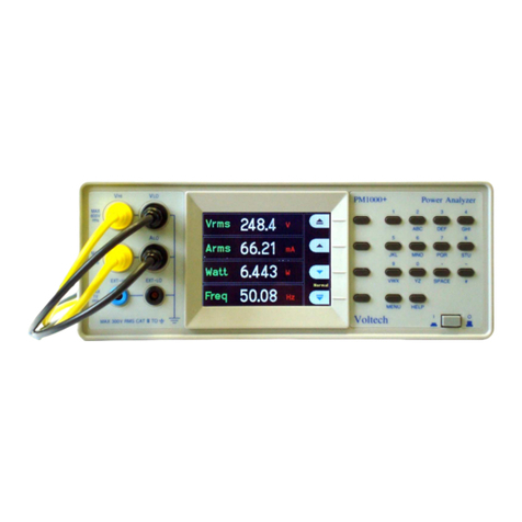
The default display shows 4 values. Each line clearly shows the measurement type
„Vrms‟, the measured value, „248.4‟ and the measurement units, „V‟. Normal
engineering notation is used to describe units, e.g. mV = milli-volts (10-3) and MV =
mega-watts (10+3).
To scroll through the measurements, use the 4 keys to the right of the display:
Jump Up
Display the page above.
Up
Move up through the measurement list.
Down
Move down through the measurement list.
Jump Down
Display the page below.

QUICK START
Page 14 © Voltech 2010 PM1000+ Power Analyzer User Manual
2.4. NAVIGATING THE MENU SYSTEM
The menu system provides complete access to all settings of the PM1000+. To access
the menu system, press the MENU key.
To return to the measurement display at any time, simply press the MENU key again.
With the menu system active, the 4 soft keys to the right of the display may be used to
navigate and select options.
MENU
MENU KEYS

QUICK START
PM1000+ Power Analyzer User Manual © Voltech 2010 Page 15
2.5. MENU KEYS
Up
Move up through the list of displayed options
Down
Move down through the list of displayed options
Up
Accept or switch on the option shown
Down
Decline or switch off the option shown
Up menu
Go up to a higher menu level
Down menu
Go down to a lower, more detailed, menu
Delete
Delete the character to the left.
OK
Accept entered data.
2.6. EXAMPLE:CHOOSING MEASUREMENTS TO DISPLAY
To choose the measurements on the display:
1. press MENU (to show the menu)
2. press (to see the list of Measurements)
Measurements with a will be displayed in the order shown.
3. Select the measurement to display and press .
4. (Option). Move the measurement
5. Press OK.
To remove a measurement, select it and press X
Hint:
To restore the default list, see the User Configuration Menu.

QUICK START
Page 16 © Voltech 2010 PM1000+ Power Analyzer User Manual
2.7. KEY SHORTCUTS
Display freeze: Press SPACE
Display graph: Press YZ
Print: Press VWX
Local control (from remote): Press #
Toggle Data Logging: Press STU
2.8. PRINTING
The PM1000+ can print to a parallel port, RS232 serial port, or, on the enhanced
comms version, to a USB printer. To configure where printing is sent, see the
Interfaces section (4.8) of this manual.
Due to the increasing variety and proprietary nature of printer standards the
PM1000+ will not support all printers. The below listed printers have been tested as
shown and work with the PM1000+.
Parallel
USB
Serial/RS232
Epson LQ 570+
Yes
NA
NA
HP Deskjet 5652
Yes
Yes
NA
HP Deskjet 930C
Yes
No
NA
Seiko DPU 414
Yes
NA
NA
Lexmark E240n
Yes
Yes
NA
Citizen (Seiko) iDP562-CNL
Yes
NA
NA
Axiohm ASTER5530/A
NA
NA
Yes
Printers Tested w/ the PM1000+
To send results to a printer, press the "VWX" key on the front panel. All the currently
selected results will be printed to the currently selected printer.

QUICK START
PM1000+ Power Analyzer User Manual © Voltech 2010 Page 17
2.9. DATA LOGGING
An Enhanced Comms version of the PM1000+ can be enabled to log data to a USB
flash drive. The unit will log all selected measurements into a comma separated
value (CSV) formatted file that is stored on the connected USB flash drive. Results
will be logged once per second.
Prior to enabling data logging, insert a USB flash drive into the USB host port on the
rear of the PM1000+.
Data logging is not available on Basic Comms versions of the PM1000+.
Warning: If the USB flash drive is removed while data logging is enabled, data
corruption will occur.
Logging Data:
To start data logging press the 8/STU key on the PM1000+ keypad. Data logging will
be indicating by the text indicating the current mode flashing every second. To stop
data logging press the 8/STU key on the PM1000+ keypad.
Data Storage and Format:
The data will be logged in a directory created by the PM1000+ on the USB flash
drive. The directory structure created will contain the last five digits of the serial
number of the PM1000+ used and the date at the start of data logging. The file name
will reflect the time at the start of data logging in 24hr format and will have a .CSV
extension.
For example, if a PM1000+ with the serial number 100008200001 begins data
logging on 29 February 2008 at 2:18:56PM, the directory tree will be as shown below.
Root Dir\PM1000+\00001\20080229\14-18-56.csv
The first portion of the file will contain a header identifying the instrument used by
serial number and the time data logging began. The second portion of the file will
contain column headers for every measurement currently selected. Subsequent lines
will contain an indexed set of the measurements currently selected, in the order
displayed on the PM1000+ screen. The basic format of the data is shown below.
Time and date will be in 24hr and year, month, day (YYYYMMDD) format
respectively.

QUICK START
Page 18 © Voltech 2010 PM1000+ Power Analyzer User Manual
Voltech Instruments PM1000+
Serial Number:
100008200001
Firmware Version
4.13RC4
Start Date (YYYYMMDD):
10/30/2008
Start Time (24hr):
8:00:33
Index
Vrms
Arms
Watt
Freq
PF
1
2.09E-01
2.90E-03
1.83E-04
0
3.02E-01
2
2.08E-01
2.90E-03
1.83E-04
0
3.03E-01
3
2.08E-01
2.91E-03
1.82E-04
0
3.01E-01
4
2.08E-01
2.90E-03
1.83E-04
0
3.02E-01
USB Flash Drive Requirements:
The USB flash drive must be formatted with FAT12, FAT16 or FAT32 file
systems.
Sector size must be 512 bytes. Cluster size up to 32kB.
Only Bulk Only Mass Storage (BOMS) devices which support the SCSI or
AT command sets are supported. For more information on BOMS devices
refer to Universal Serial Bus Mass Storage Class –Bulk Only Transport
Rev. 1.0, published by the USB Implementers Forum.
2.10. UNIT CONFIGURATION
To view unit configuration data including hardware revision, firmware revision, serial
number, date and type of last adjustment, and whether IEC mode has been enabled,
using the menu system, select:
System Configuration → Unit Configuration
Explanation of Adjustment Type
The following descriptions are possible for adjustment type.
Adjustment
Type
Explanation
None
No adjustment applied.
Limited
Adjustment of limited range of magnitude and frequency.

USING VOLTAGE AND CURRENT TRANSDUCERS
PM1000+ Power Analyzer User Manual © Voltech 2010 Page 20
3. USING VOLTAGE AND CURRENT TRANSDUCERS
3.1. INPUT OVERVIEW
Voltage
Voltages of up to 600V rms may be connected directly to the black and yellow 4mm
VHI and VLO safety sockets at the front of the PM1000+
Current
Currents of up to 20A rms may be connected directly to the black and yellow 4mm AHI
and ALO safety sockets at the front of the PM1000+
External Current Inputs
The external current inputs accept a voltage of up to 1V rms that is proportional to the
current being measured. This input allows a very wide range of external current
transducers to be connected, from low mA current shunts to MA current transformers.
For each type of transducer, the PM1000+ may be scaled to read the correct current.
See the INPUTS menu.
The choice of current transducer will depend on:
The current being measured, including peaks and transients.
The accuracy required.
The bandwidth required: Unless the waveforms are purely sinusoidal, a bandwidth
in excess of the fundamental frequency will be required.
Whether there is DC current present.
Convenience of connection –E.g. using a clamp-on current transformer, with jaws
that open, for quick connection in a fixed wiring loom.
The effect of the transducer on the circuit.
Other manuals for PM1000+
1
Table of contents
Other Voltech Measuring Instrument manuals
Popular Measuring Instrument manuals by other brands

Oregon Scientific
Oregon Scientific RGR122 user manual

Badger Meter
Badger Meter M-series Installation and operation manual

TSI Instruments
TSI Instruments AirPro AP500 quick start guide

Roughneck
Roughneck 67151 owner's manual

Meco
Meco DU-96 user manual

PCB Piezotronics
PCB Piezotronics IMI SENSORS 607M83 Installation and operating manual