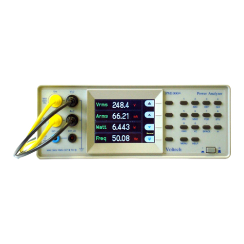
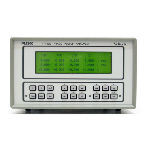
Voltech PM6000 User manual

PM6000
POWER ANALYZER
USER MANUAL
VOLTECH PM6000 USER MANUAL ISSUE 19 PAGE I
Voltech Instruments Inc.
11637 Kelly road Suite 306
Fort Myers FL33908
U.S.A.
Tel: 239 437 0494
Fax: 239 437 3841
Voltech Instruments Ltd.
148 Harwell Business Centre
Didcot Oxon OX11 0RA
U.K.
Tel: +44 1235 834555
Fax: +44 1235 835016
www.voltech .com

Voltech Instruments is committed to a policy of continuous product development.
Hence product specification and the information given in this manual are subject to
change without notice.
No part of this publication may be reproduced stored in a retrieval system or
transmitted in any form or by means electronic mechanical photocopying
recording or otherwise without prior written permission of Voltech Instruments.
2005 - 2011 Voltech Instruments. All rights reserved.
Microsoft Windows and the Windows logo are either registered trademarks or
trademarks of Microsoft Corporation in the United States and/or other countries.
Voltech Part Number: 98-058
Manual Issue PM6000 Firmware Revision
20 v1.21.07RC2
PAGE II VOLTECH PM6000 USER MANUAL ISSUE 19

DANGER OF ELECTRIC SHOCK
Only qualified personnel should install this equipment after reading and
understanding this user manual. If in doubt consult your supplier.
RISQ E D'ELECTROC TION
L'installation de cet équipement ne doit être confiée qu'à un personnel
qualifié ayant lu et compris le présent manuel d'utilisation. Dans le
doute s'adresser au fournisseur.
GEFAHR VON ELEKTRISCHEM SCHOCK
Nur entsprechend ausgebildetes Personal ist berechtigt diese
Ausrüstung nach dem Lesen und Verständnis dieses
Anwendungshandbuches zu installieren. Falls Sie Zweifel haben sollten
wenden Sie sich bitte an Ihren Lieferanten.
RISCHIO DI SCARICHE ELETTRICHE
Solo personale qualificato può installare questo strumento dopo la
lettura e la comprensione di questo manuale. Se esistono dubbi
consultate il vostro rivenditore.
IMPORTANT: Please consult the safety information section of this user manual before
installation and use.
VOLTECH PM6000 USER MANUAL ISSUE 20 PAGE III
!
!
!
!

PAGE IV VOLTECH PM6000 USER MANUAL ISSUE 19

Contents
1. Introduction ............................................................................ 1
1.1. Features & Abilities .............................................................................................. 1
1.2. Package Contents ............................................................................................... 3
1.3. Options ................................................................................................................ 4
2. Quick Start .............................................................................. 1
2.1. Getting Started .................................................................................................... 1
2.2. Navigating the Menu System ............................................................................... 1
2.3. Measurement Display .......................................................................................... 3
2.4. Wiring and Groups ............................................................................................... 4
2.5. Summary ........................................................................................................... 12
3. Menu System .......................................................................... 1
3.1. Navigation ............................................................................................................ 1
3.2. Menu Items .......................................................................................................... 2
4. Remote Operation .................................................................. 1
4.1. Overview .............................................................................................................. 1
4.2. Interfacing with GPIB systems ............................................................................. 1
4.3. Interfacing with RS232 Systems .......................................................................... 1
4.4. Interfacing With Ethernet Systems ....................................................................... 1
4.5. Remote Command Syntax and Conventions ....................................................... 2
4.6. Status Reporting .................................................................................................. 3
4.7. IEEE488.2 Common Commands ......................................................................... 4
4.8. Format Commands .............................................................................................. 8
4.9. Configuration Commands (:CFG command) ...................................................... 29
4.10. :INP Commands .............................................................................................. 33
4.11. :INST Commands ............................................................................................ 34
4.12. :SENS Commands ........................................................................................... 37
4.13. :SYST Commands ........................................................................................... 38
4.14. Examples of Using Commands ........................................................................ 41
VOLTECH PM6000 USER MANUAL ISSUE 20 PAGE V

5. Remote Access ...................................................................... 1
5.1. Connecting to the PM6000 using ethernet ........................................................... 1
5.2. FTP ...................................................................................................................... 3
6. Fitting Options ...................................................................... 1
6.1. Voltech Shunts .................................................................................................... 1
6.2. PCMCIA Cards .................................................................................................... 1
7. Software .................................................................................. 1
7.1. IEC 61000-3-2/3 Current Harmonics and Flicker Software .................................. 1
7.2. PM6000 Visual Power Analysis Software (PM6VPAS) ........................................ 1
8. Specification ........................................................................... 3
8.1. Measuring Channel .............................................................................................. 3
8.2. Mechanical and Environment ............................................................................... 3
8.3. External input ....................................................................................................... 4
8.4. Peripheral Ports ................................................................................................... 5
8.5. Measured Parameters ......................................................................................... 8
8.6. Measurement Accuracy ..................................................................................... 11
8.7. Regulatory Compliance ..................................................................................... 15
8.8. Shunts – 30A and 1A ......................................................................................... 16
9. Warranty, Service and pdates ............................................ 1
9.1. Warranty .............................................................................................................. 1
9.2. Calibration and Service ........................................................................................ 2
9.3. Obtaining Service and Applications Support ........................................................ 2
9.4. Updating Firmware .............................................................................................. 2
10. Safety Information ............................................................... 1
10.1. Safety Features ................................................................................................. 1
10.2. Safety Instructions ............................................................................................. 1
11. Release History .................................................................... 1
PAGE VI VOLTECH PM6000 USER MANUAL ISSUE 19

INTRODUCTION
1. INTROD CTION
1.1. FEAT RES & ABILITIES
The Voltech PM6000 is a powerful and versatile precision power analyzer. The
accuracy and bandwidth of the PM6000 allow definitive measurements of all power
quantities to be made on all electrical and electronic products. In applications ranging
from a power supply operating in standby mode through high-frequency power
converters to large power transformers the PM6000 provides stable reliable and
accurate measurements every time.
VOLTECH PM6000 USER MANUAL ISSUE 20 PAGE 1
use this Voltech product. If you experience any difficulty during
installation or use of the Voltech PM6000 or are unsure of any of its
features or abilities please do not hesitate to contact either your
local Voltech supplier or one of our Voltech main service centers.

INTRODUCTION
Versatile Technology
The PM6000 couples a fast PCI bus architecture with powerful digital signal processing
to provide 5 mega-samples per second (MSPS) - processed on all channels -
simultaneously and continuously. This ensures that accurate real-time measurements
can be made on products such as power supplies motor drives and lighting ballasts.
Up to 40 MSPS are available for burst and transient measurement modes.
There is room for up to 6 wattmeter channels to be installed into a PM6000 with a
variety of shunts and current sensors creating flexible test options.
Rugged Performance
Each measurement channel can measure up to 2000Vpk and can accept a range of
Voltech plug-in current shunts and other current transducers. The PM6000
automatically recognizes Voltech shunts when the instrument is powered up and reads
the shunt’s own calibration data to ensure optimum accuracy. In this way only the
standard measurement channel is required for all applications.
An embedded PC running the Linux operating system is used to display communicate
and control all the available measurements.
Easy to use
The display soft keys and rotary control are used to select and group measurements
display multi-phase sum quantities calculate efficiency and to display waveforms. The
menu items may also be selected using the front panel short-cut keys or remotely on a
PC.
In this way the PM6000 can be set up to make complex measurements in seconds.
Front panel settings may be stored for future use.
For on the spot assistance a comprehensive help system is built in to the analyzer.
Evolving capability
A program of software enhancement is further developing the power of the PM6000.
Regularly visit the Voltech website to keep up to date with developments
VOLTECH PM6000 USER MANUAL ISSUE 20 PAGE 2

INTRODUCTION
1.2. PACKAGE CONTENTS
The following items are supplied with your PM6000.
Please check that you have every item and report any missing items to your Voltech
supplier as soon as possible.
•PM6000 Chassis (NOTE: No floppy disk is fitted on models sold after February
2008)
•Certificate of Conformance and Calibration Certificates
•CD including the manual and calibration data
•Mains power cable
•Current Connector plug for each measurement card
•Ethernet Crossover cable for direct PC to PM6000 connection
•Voltech product registration card
Returning your product registration card will ensure that you continue to receive the
latest product and application information.
If you have ordered measuring channels and shunts together with a PM6000 chassis
they will be fitted ready for use.
VOLTECH PM6000 USER MANUAL ISSUE 20 PAGE 3

INTRODUCTION
1.3. OPTIONS
The following items may also be supplied with the PM6000. For logistical reasons
some items may be supplied in separate packages. All these items are also available
post sale.
•PM6000 Measurement Channel (Fitted by a Voltech service center only)
High performance wattmeter channel. Voltage 2000Vpk current 2.5Vpk for
shunt or current transducer. ±5Vdc isolated supply (at current channel
potential) and ±12dc supply (at chassis potential) for external current
transducer
•1A Shunt
1Arms 5Apk precision measuring shunt with calibration stored in EPROM
•30A shunt
30Arms 250Apk precision measuring shunt with calibration stored in
EPROM
•Lead set
2 pairs (yellow and black) 1.5m 2000V 32A leads with safety connectors and
alligator clips
•Rack mounting kit
For 19” 3 ½ U high
•Internal hard drive
For storage of user data
VOLTECH PM6000 USER MANUAL ISSUE 20 PAGE 4

QUICK START
2. Q ICK START
2.1. GETTING STARTED
1. Check the power analyser is in good condition with the correct number of
measurement channels and shunts fitted
2. Connect the power cable. Ensure the supply is Earth grounded.
3. Press the power switch at the rear to ON (I)
4. Press the front panel power switch
The instrument will start its power up sequence. This takes approximately
one minute
Once completed the display should show columns for the measurement
channels
5. The instrument is now ready for use
2.2. NAVIGATING THE MEN SYSTEM
The menu system provides complete access to all settings of the PM6000. The menu
system may be accessed as follows:
1. By use of the 6 soft keys found to the right of the display
2. By using the short-cut keys on the front panel. These keys are grouped in a
logical left to right sequence for setting up the instrument and provide fast
access to the top-level menu items. Additional keys may be used to store your
own short cuts to frequently used menu items [MENU1] [MENU2] and
[MENU3].
Press the [HELP] key at any time to activate the in-built context sensitive
help system.
For optimum ease of use the actions that the soft keys will take is adjusted to suit the
measurement display or menu point shown on the display. The key action is described
by a simple graphic symbol that is shown in alongside each key
In most situations pressing the [Menu] key is the quick way to exit the menu system
VOLTECH PM6000 USER MANUAL ISSUE 20 PAGE 1

QUICK START
Down Menu View the details of the selected menu item.
p Menu Go back up the menu system.
Accept Accept the choice or save the setting.
Cancel Cancel setting exit without saving.
p Move up or through the menu or measurements.
Down Move down through the measurements.
Rotate Display the next group or trigger.
Left Display the measurement column to the left.
Right Display the measurement column to the right.
? Help Switch the help display on or off.
DEL Delete Delete one character to the left of the cursor.
CLR Clear Clear the current alpha or numeric entry.
ESC Escape Escape from the menu without saving changes.
OK Save Save changes.
Rotary
The rotary knob is used to scroll up and down through measurements or menu items
VOLTECH PM6000 USER MANUAL ISSUE 20 PAGE 2

QUICK START
2.3. MEAS REMENT DISPLAY
The display may be used to show numerical results graphics or both. (See the
[GRAPH] [FORMAT] menu for details).
Numerical measurements are organized like a spreadsheet with the measurement
channels (and groups of channels) in columns and the measured parameters (e.g.
watts volts amps) in rows.
Status Group A Group B Group B Group B
CH1 CH2 CH3 SUM
Vrms
Arms
W
VA
VAr
To display further measurement columns use the left and right keys .
To display further measured parameters use the up and down keys .
When no further measurements are available these keys are shown in gray.
To group channels together to display sum quantities see the [WIRING] menu
description.
To hide numeric results columns see the [FORMAT] [DISPLAY COLUMNS] menu
The Status area is used to show important status indicators such as an over-range
(OVR) on a measurement input or if [HOLD] has been pressed.
VOLTECH PM6000 USER MANUAL ISSUE 20 PAGE 3
Channels
Measurements

QUICK START
2.4. WIRING AND GRO PS
The analyzer uses the concept of groups of measurement channels for many of its
functions. By default each channel is assigned to its own group so Channel 1 is Group
A Channel 2 is Group B and so on.
For multiphase measurements a number of channels can be assigned to a group
allowing precise frequency and phase analysis of the multiphase signals. The
frequency of the first channel in the group is used as the fundamental frequency for all
channels in the group and all phase measurements are relative to the phase reference
(Voltage by default) of the first channel in the group.
Channels are assigned to a group by selecting the required wiring configuration from
the [WIRING] menu or by remote commands. The appropriate number of adjacent
channels will be included in the group.
This should be done before connecting the test leads to avoid confusion when wiring
up to the PM6000
Channel 1
VOLTECH PM6000 USER MANUAL ISSUE 20 PAGE 4
•Figure 1 Rear View of Instrument

QUICK START
•Figure 2 Common Wiring Configurations
VOLTECH PM6000 USER MANUAL ISSUE 20 PAGE 5

QUICK START
1. In the [WIRING] menu choose how you wish to group measurements together
if required
In this example CH1 and CH2 have been grouped together to measure a 3-phase
input and CH3 and CH4 have been grouped together to simultaneously measure a
3-phase output
2. Choose and set up current and voltage transducers as required and described
below.
3. Then make the physical connections taking care to observe health and safety
regulations.
Each measurement channel has inputs for both voltage and current. The inputs are
fully isolated from each other and from ground. The instrument chassis must be Earth
grounded at all times
VOLTECH PM6000 USER MANUAL ISSUE 20 PAGE 6

QUICK START
For a discussion of three-phase measurements see Voltech application note 104-022
‘Three-Phase Measurements’.
The three-phase 7-wire configuration may be used to measure total power on
distribution systems with center-tapped three-phase transformers. The connection
method is similar to the three-phase 4-wire 3-wattmeter method above with all VLO
terminals of the analyzer common and a VHI terminal taken to each of the 6 line wires
VOLTECH PM6000 USER MANUAL ISSUE 20 PAGE 7

QUICK START
2.4.1 Voltage and Current Input Overview
Voltage
Voltages of up to 2000V peak may be connected directly to the black and yellow 4mm
safety sockets at the bottom of the channel. A yellow and black lead set is provided
with each voltage channel. When connecting the leads ensure that the end closes to
the ferrite bead is connected to the PM6000.
Current
The measurement channel accepts a voltage of up to 2.5Vpk that is proportional to the
current being measured. This input allows a very wide range of external current
transducers to be connected from low mA current shunts to MA current transformers.
For each type of transducer the PM6000 may be scaled to read the correct current.
See the [SCALING] menu.
Any combination of Voltech shunts or other transducers can be used simultaneously on
different channels of the PM6000
The choice of current transducer will depend on:
•The current being measured including peaks and transients.
•The accuracy required.
•The bandwidth required: Unless the waveforms are purely sinusoidal a bandwidth
in excess of the fundamental frequency will be required.
•Whether there is DC current present.
•Convenience of connection – E.g. using a clamp-on current transformer with jaws
that open for quick connection in a fixed wiring loom.
•The effect of the transducer on the circuit.
VOLTECH PM6000 USER MANUAL ISSUE 20 PAGE 8

QUICK START
2.4.2 To connect an external resistive shunt:
1. Use the plug supplied to make the connections to the measurements
channel connections
2. Use good quality shielded twisted pair cable to minimize pick-up
•Figure 3 External Resistive Shunt with Shielded Twisted air
3. For optimum rejection of common mode signals the 0V guard terminal
must be used. Connect this to the shield of the twisted pair cable if
VOLTECH PM6000 USER MANUAL ISSUE 20 PAGE 9
0V – Guard terminal
± 5V isolated supply at shunt potential

QUICK START
available. If there is no shield connect this directly to the ELO terminal
4. Enter the value in mΩ of the external shunt into the PM6000. See the
[SCALING] [External Shunt mV/A] menu. E.G. For a 100mΩ shunt enter
the value 100
2.4.3 To connect a transducer with a voltage output
(E.g. Hall-effect current transformer)
VOLTECH PM6000 USER MANUAL ISSUE 20 PAGE 10
Voltage Input VHI VLO
DO NOT USE Incorrect use will damage PM6000
Connections for Voltech accessories only
Voltage input 2.5V pk max.
For current transducers with a voltage output
± 12V @100mA external transducer supply.
NON ISOLATED 0V at Chassis ground
Table of contents
Other Voltech Measuring Instrument manuals