Q
UICKSTART
GUIDE
PTX800A
QS61001051 • 12/2005
Operation
General
The PTX800A is a scalable totaliser/rate indicator for analogue rate
signals. It will display either the rate or total according to setup. The
other value is displayed when you hold down the TOTAL/RATE key.
For more complex applications, the PTX800A can be supplied with
two alarm channels and/or an analogue re-transmit output.
Alarm conditions are indicated by the LEDs above buttons marked AL1
(for alarm channel one) and AL2 (for alarm channel two).
Manually clearing tripped alarms
The alarm channels can be set for automatic or manual reset. For
manual reset, the LED will flash when an alarm trips. These alarms will
only clear if you have acknowledged the alarm and the trip condition
has cleared. Press AL1 or AL2 to acknowledge the alarm.
Viewing the alarm setpoints
Press the AL1 or AL2 at any time to display the setpoint for that
channel. The value will be shown for 5s. If the alarms are disabled,
pressing the key will have no effect.
Changing the alarm setpoints
Press PGM while the setpoint is on display (see above), you will be able
to change the value using the ìand Åkeys. To save the changes,
press PGM. Note: you can disable this feature during setup for greater
security.
Checking the Rate/Total
You can set up the PTX800A to show either total or rate. If the total
is normally on display, you can check the rate by holding down the
TOTAL/RATE key.
Resetting the total
If you press the RESET key, the PTX800A will set the total to zero and
clear any total alarms (you can disable this feature during setup for
greater security). There is also an external reset input that you can use
to clear the total remotely.
Reviewing the setup options
To review the setup (in read only mode) press the PGM key. The
PTX800A will show the software version number. Press the Åkey to
see the next setting. The information in review mode is shown in the
same order as setup mode (however decimal point and some disabled
feature information will be skipped).
There is a 10s timeout during review mode or you can press PGM again
to return the display to normal operation.
You can review the setup while the instrument is in service - the unit
will continue to operate normally. Setup mode
Changing the setup options
Use setup mode if you have to change a setting or calibrate the
outputs. The setup mode stops all operation. As soon as you have
setup the last parameter, the unit behaves as if it has been switched on
with the new settings. This does not mean that the total is reset - you
must do this yourself if necessary.
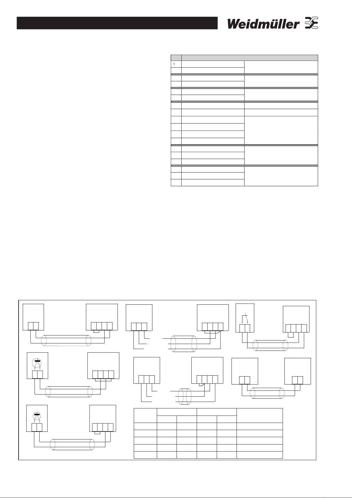
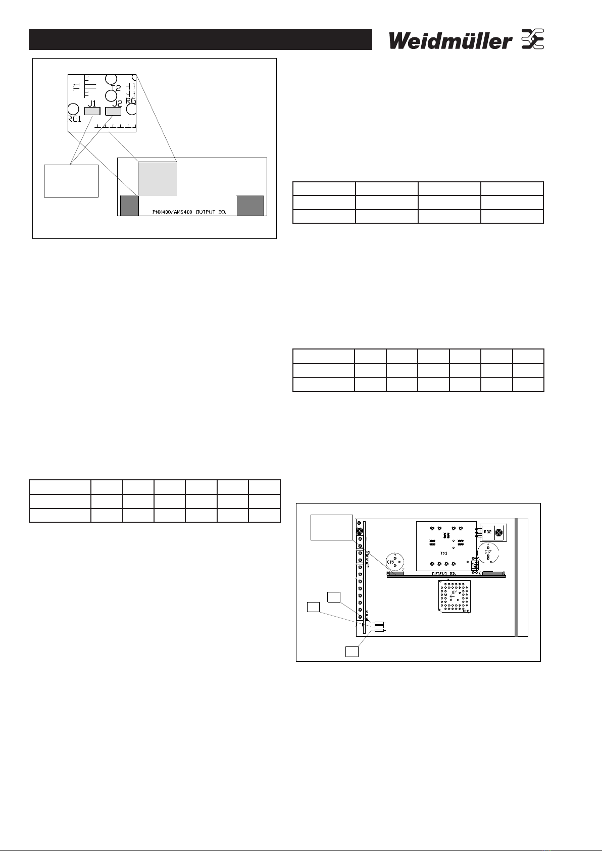
PTX800A
Analogue output
(gives rate or total)
Pulse Output
Analogue (mA or V)
Rate Input
Total or
Rate Display
Power for Input device
Reset Pulse Input
Alarm 2
Power
Supply
Alarm 1
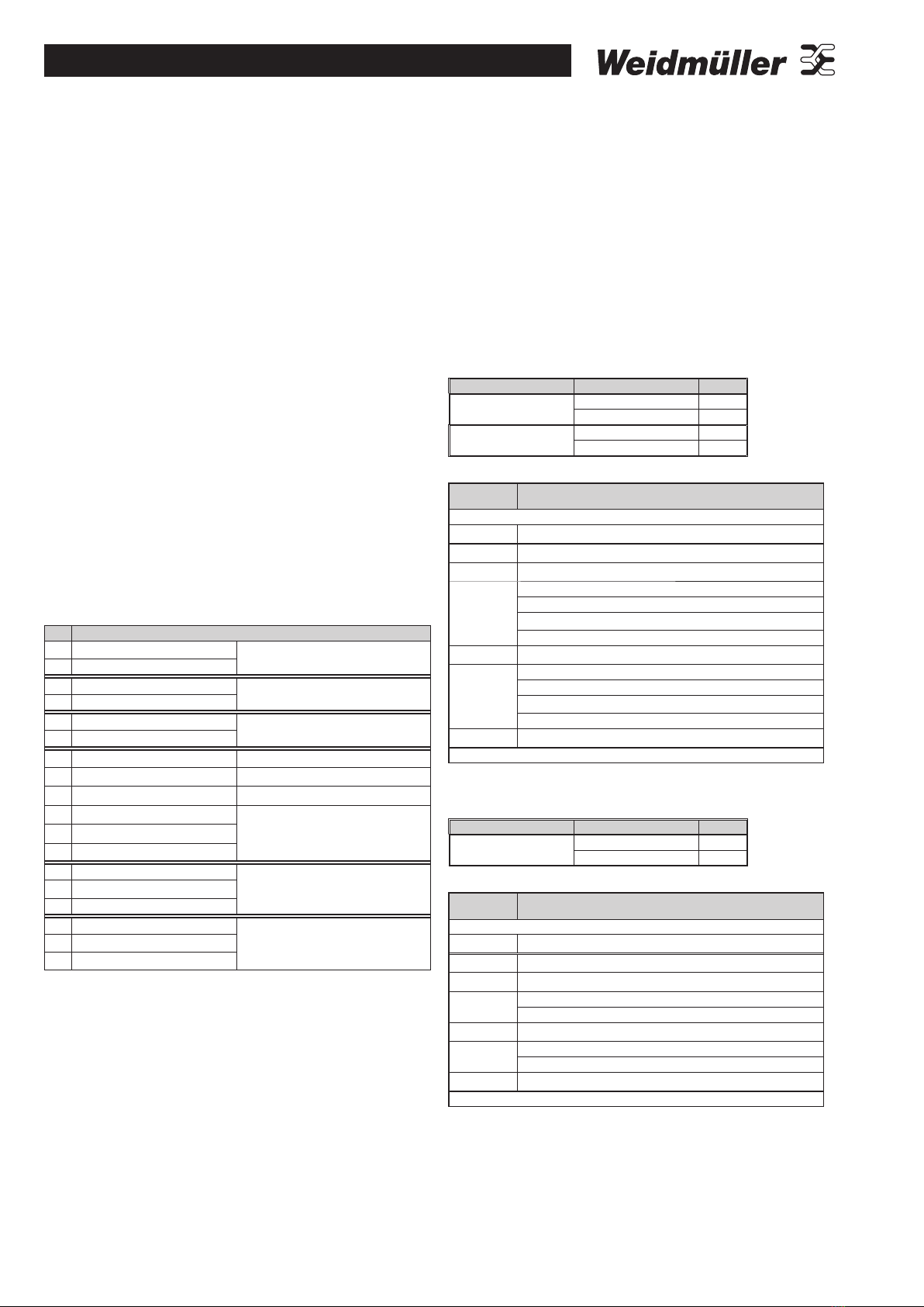
If you want to abandon all the changes you have made, simply remove
the security link (or remove the power) before the save message is
shown.
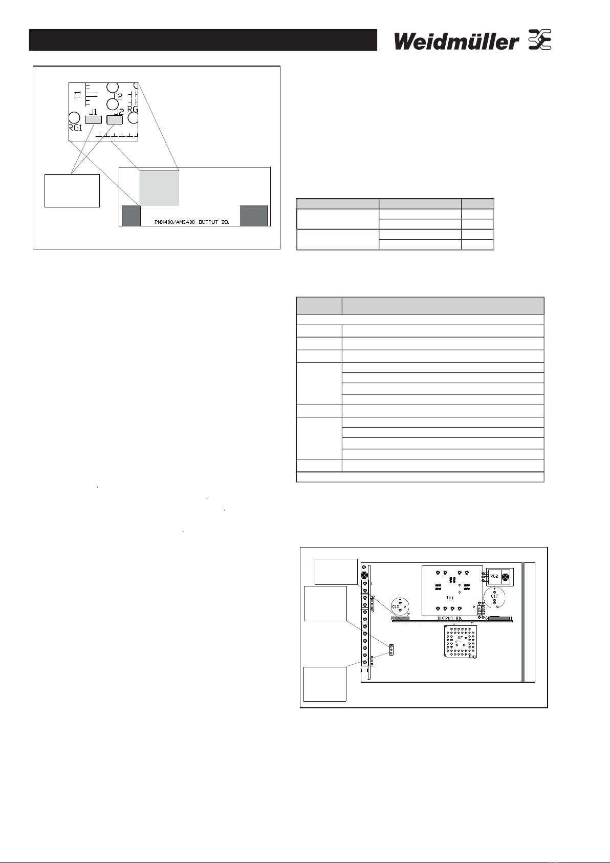
To change the instrument setup:
1. Connect the security link (short pins 8 & 9).
2. Press the PGM key.
The setup sequence is shown in the table on page two.
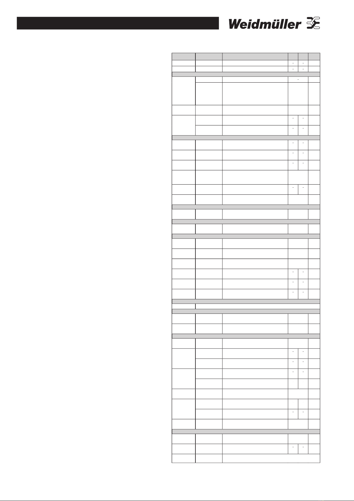
Setup options
General
There are four basic areas of the instrument operation that must be
setup on a fully configured PTX800A. They are:
• Analogue Current/Voltage inputs;
• Display and keypad operation;
• Alarms one and two (optional); and
• Analogue outputs (optional).
You can disable the alarms and/or analogue outputs if you do not need
them (if so their settings will not be displayed).
Software version
The information in this guide refers to versions 1.00 to 1.11.
Input signal type and range
You can not change the input type during set-up mode. The input is
either current or voltage according to the components used when the
unit was built.
The input range is determined by the values supplied during
calibration. So, if you change the range displayed in setup, you will
have to calibrate the inputs.
Damping Factor
The PTX800A uses digital filtering to smooth the input signal. The
damping factor sets the amount of filtering from minimum damping
(factor of one) to the maximum (factor of ninety nine).
Transfer Function
To use the PTX800A with square law rate measuring devices, like
differential pressure cells, set the transfer function to square law.
Otherwise use a linear setting. For more complex relationships
between rate and signal level you can use a CLC/AR to linearise your
input signal.
Low cut-out rate
To prevent accumulated errors at low input levels, you can set a low
cut-out rate. When the input is below this value the total does not
increase.
Total decimal point
The total decimal point position sets the number of decimal places for
the total display. Totals are displayed using the full eight digits.
Rate decimal point
Sets the number of decimal places for the rate display. Rates are
displayed as five digit numbers.
Total scaling factor
The total scaling factor sets the ratio between the total display and the
rate display. It must be a power of ten (i.e., 1000,100, ..., 0.01, or 0.001).
Number of samples
The PTX800A calculates the rate every 260mS. The analogue output
and display are then updated from the average over the programmed
number of samples. For example, if you set the number of samples to
10, the analogue output and rate display will be updated every 2.6s.
Rate timebase
The rate timebase setting sets the timebase for the rate display. It can
be set to days, hours, minutes or seconds.