manuals.online logo
Brands
  1. Home
  2. •
  3. Brands
  4. •
  5. LOVATO ELECTRIC
  6. •
  7. Measuring Instrument
  8. •
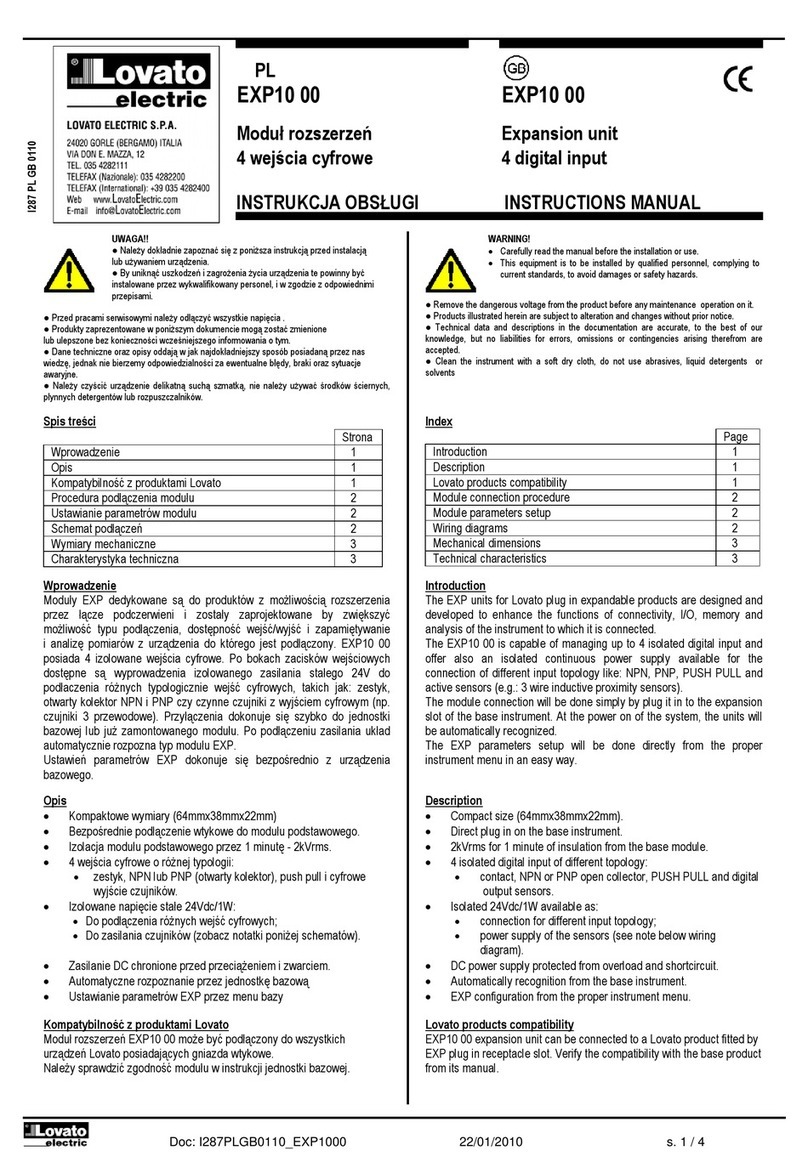
  9. LOVATO ELECTRIC EXP10 04 User manual

LOVATO ELECTRIC EXP10 04 User manual

Doc: I291PLGB0410_EXP1004 29/04/2010 s. 1 / 3
PL
EXP10 04
EXP10 04
Moduł rozszerzeń Expansion unit
2 izolowane wejścia analogowe 2 isolated analog inputs
wielo unkcyjne multi unction
INSTRUKCJA OBSŁUGI
INSTRUCTIONS MANUAL
● Przed pracami serwisowymi, należy odłączyć wszystkie napięcia od wejść
pomiarowych i zasilania pomocniczego oraz zewrzeć zaciski przekładnika
prądowego.
● Prod kty zaprezentowane w poniższym dok mencie mogą zostać zmienione
l b lepszone bez konieczności wcześniejszego informowania o tym.
●
Dane techniczne oraz opisy oddają w jak najdokładniejszy sposób posiadaną
przez nas wiedzę, jednak nie bierzemy odpowiedzialności za ewent alne błędy,
braki oraz syt acje awaryjne.
● W kładzie należy zamontować rozłącznik (wyłącznik), który m si znajdować
się niedaleko rządzenia i być łatwo dostępny dla operatora. M si spełniać wymogi
następ jących norm: IEC/ EN 61010-1 § 6.12.2.1.
● Należy mieszczać rządzenie w ob dowie l b szafie o minimalnym stopni
ochrony IP40.
● Należy czyścić rządzenie delikatną s chą szmatką, nie należy żywać środków
ściernych, płynnych detergentów l b rozp szczalników.
●
Remove the dangero s voltage from the prod ct before any maintenance
operation on it.
● Prod cts ill strated herein are s bject to alteration and changes witho t prior
notice.
● Technical data and descriptions in the doc mentation are acc rate, to the best
of o r knowledge, b t no liabilities for errors, omissions or contingencies arising
therefore are accepted.
● A circ it breaker m st be incl ded in the electrical installation of the b ilding. It
m st be installed close by the eq ipment and within easy reach of the operator.
It m st be marked as the disconnecting device of the eq ipment:
IEC /EN 61010-1 § 6.12.2.1
● Fit the instr ment in an enclos re or cabinet with minim m IP40 degree
protection.
● Clean the instr ment with a soft dry cloth, do not se abrasives, liq id
detergents or solvents
Wprowadzenie
Mod ły EXP dedykowane są do prod któw z możliwością rozszerzenia
przez gniazda wtykowe i zostały zaprojektowane by zwiększyć możliwość
typ podłączenia, dostępnoćć wejść/wyjść, zapamiętywanie
i analizę pomiarów z rządzenia do którego jest podłączony.
EXP1004 zapewnia dwa wielof nkcyjne izolowane wejścia analogowe
a każde z nich może być wykorzystane do pomiar napięcia, prąd l b
temperat ry z cz jnika PT100. Może być podłączony do każdego
z rządzeń Lovato, które wyposażone jest w gniazda wtykowe.
Przyłączenia dokon je się szybko do jednostki bazowej. Po podłączeni
zasilania kład a tomatycznie rozpozna typ mod ł EXP. Ustawienia
parametrów EXP dokon je się w prosty sposób bezpośrednio przez
rządzenie bazowe.
Introduction
The EXP nits for Lovato pl g in expandable prod cts are designed and
developed to enhance the f nctions of connectivity, I/O, memory and
analysis of the instr ment to which it is connected.
The EXP10 04 is capable of managing 2 isolated m ltif nction analog
inp ts and each one can be sed for meas ring voltage, c rrent or
temperat re with PT100 sensor.
The mod le connection will be done simply by pl g it in to the expansion
slot of the base instr ment. At the power on of the system, the nits will
be a tomatically recognized.
The EXP parameters set p will be done directly from the proper
instr ment men in an easy way.
Opis
• Wymiary (64mmx38mmx22mm).
• Montaż wtykowy do jednostki bazowej.
• Izolacja od rządzenia bazowego i pomiędzy wejsciami 4kVrms.
• 2 wielof nkcyjne analogowe wejścia, każde programowalne:
•
Zakres napięcia 0÷10V l b ±5V;
•
Zakres prąd 0…20mA l b 4…20mA;
•
Temperat ra (cz jnik PT100 z 2 przewodami) w zakresie
-50…250°C.
Description
• Compact size (64mmx38mmx22mm).
• Direct pl g in on the base instr ment.
• 4kVrms of ins lation from the base mod le and between the inp ts.
• 2 m ltif nction analog inp ts each one programmable for:
•
voltage with 0÷10V or ±5V range;
•
c rrent with 0÷20mA or 4÷20mA range;
•
temperat re (2 wires PT100 sensor) with -50°C÷250°C range.
Kompatybilność z
produktami
Lovato
Mod ł EXP10 04 może być podłączony do wszystkich rządzeń Lovato
Electric posiadających gniazda wtykowe do EXP. Sprawdź kompatybilność
w poniższej tabeli:
Jednostka bazowa
Wersja oprogramowania J.
B.
DMG800
>= 0
3
DMG900
>= 0
1
Lovato products compatibilit
y
EXP10 04 can be connected to a Lovato Electric prod ct fitted by EXP
receptacle slot. Verify the compatibility with the following table:
Base device
Base device SW Rev.
DMG800
>= 0
3
DMG900
>= 0
1
I291PLGB
04
10
UWAGA
!!
● Należy dokładnie zapoznać się z poniższa instr kcją przed
instalacją l b żywaniem rządzenia.
● By niknąć szkodzęń i zagrożenia życia rządzenia
te powinny być instalowane przez wykwalifikowany personel,
i w zgodzie z odpowienimi przepisami.
WARNING!
• Caref lly read the man al before the installation or se.
• This eq ipment is to be installed by q alified personnel,
complying to c rrent standards, to avoid damages or safety
hazards.
UWAGA
!
● Kiedy mod ł EXP jest zamontowany w miernik DMG,
należy koniecznie zamontować osłonę zacisków
dostarczaną z miernikiem.
WARNING!
•
When the EXP. mod le is installed on a DMG series
m ltimeter, it is mandatory to install the sealable
terminal block covers s pplied with the m ltimeter
.
Doc: I291PLGB0410_EXP1004 29/04/2010 s. 2 / 3
Procedura podłączenia modułu
Module
connection procedure
1.
Odłączyć niebezpieczne napięcie
.
2. Należy zdjąć osłonę zacisków i zaciski przyłączeniowe.
3. Następnie należy zdjąć osłonę otwor montażowego w prod kcie
Lovato, w miejsc gdzie EXP będzie zamontowany.
4. Należy włożyć mod ł EXP10 04 jak pokazano na powyższym
rys nk .
5. Należy ponownie mieścić osłonę zacisków i zaciski przyłączeniowe.
6. Następnie włączyć zasilanie (jednostka bazowa a tomatycznie
rozpozna podłączony mod ł).
UWAGA: w cel s nięcia mod ł EXP (przy odłączonym zasilani
i wymontowanych zaciskach przyłączeniowych, które mogą przeszkadzać
w demontaż ) należy wykonać czynności w odwrotnej kolejności (od
p nkt 5 do 2). Wcisnąć p nkt wskazany gwiazdką (*) i wyciągnąć mod ł.
1.
Remove any dangero s voltage
.
2. Remove the terminal covers and the terminal block.
3. Remove the expansion slot cover of the Lovato prod ct at the
position in which the EXP will be pl g in.
4. Insert the EXP10 04 as ill strated in the above pict re.
5. Replace the terminal block and the terminal cover.
6. Power p the system (the base prod ct will a tomatically
recognize the expansion nit).
NOTE: Remove any dangero s voltage and repeat the operations from
step 5 to step 2 in the opposite direction. Press in the point indicated by
the * in the pict re in order to remove the mod le.
Ustawianie parametrów modułu
W cel stawienia parametrów mod ł EXP należy zapoznać
się z instr kcją główną rządzenia bazowego..
Module parameters setup
For the EXP parameters config ration, see the man al of the main
prod ct to which it intends to connect.
Schematy połączeń
Wiring diagram
Pozycja zacisków
Terminal blocks position
Podłączenie wejść
Inputs connection
Wymiary mechaniczne
[
mm
]
Mechanical dimensions
[
mm
]
Connessione per ingresso di correnteConnessione P 100 2 fili
2 wire P 100 connection
0-10V
+/- 5V
Voltage input connection
Connessione per ingresso di tensione
_
+
4-20mA
0-20mA
_
+
Current input connection
CLAC!
1 2 3
*
Slot Slot Slot Slot
1 2 3 4
Doc: I291PLGB0410_EXP1004 29/04/2010 s. 3 / 3
Zasilanie pomocnicze
Supply
Napięcie zasilania
5V=
(dostarczane przez rządzenie
bazowe)
S pply voltage
5V=
(s pplied by main instr ment)
Pobór prąd
30mA
S pply c rrent
30mA
Pobór/rozproszenie mocy
0,2W
Power cons mption/dissipation
0.2W
Wej
ś
cia
Inputs
Ilość
kanałów
2
N mber of ch
annels
2
Ilość wej
ś
ć
dostępnych naraz na kanał
1
na każdy kanał
N mber of possible inp ts at once per
channel
1
Wejście temperatury
Temperature input
Typ cz jnika
PT100
/ 2 przewody
Sensor type
2 wires PT100
Zakres pomiar
-
50...2
50°C
Meas ring range
-
50°C…250°C
Dokładność (błąd pomiar )
0,2%
pełnej skali
±1
cyfra
Precision (meas ring error)
0,2% of F.S. ±1digit
Rozkład
0,1°C
Resol tion
0,1°C
Wejścia prądowe
Current input
Zakres pomiar
(
programowalny
)
0…20mA
4…20mA
Meas ring ranges (programmable)
0…20mA
4…20mA
Rezystancja wejscia
360

Inp t resistance
360

Dokładność (błąd pomiar )
0,1%
pełnej skali przy
25°C±1
cyfra
Precision (meas ring error)
0,1% F.S. at 25°C±1digit
Rozkł
a
d
1µA
Resol tion
1µA
Czas odpowiedzi
200ms
Response time
200ms
Wejścia napięciowe
Voltage input inp
ut
Zakres pomiar
(
programowalny
)
0…10V
±5V
Meas ring ranges (programmable)
0…10V
±5V
Rezystancja wej
ś
cia
>100K

Inp t resistance
>100K

Dokładność (błąd pomiar )
0,1%
pełnej skali przy
25°C±1
cyfra
Precision (meas ring error)
0,1% F.S. a 25°C±1digi
t
Rozkład
1mV
Resol tion
1mV
Czas odpowiedzi
200ms
Response time
200ms
Podłączenie wej
ś
ć
Inputs connection
Podłączenie
Wtykowe/wyjmowane
Connection
Pl g in/Removable termina type
Ilość
bloków zacisków
2
N mber of terminals block
2
Ilość zacisków
4
N mber of terminals
4
Przekrój przewod (min
–
maks)
0,2...1,5 mmq (28
÷
14 AWG)
Cable cross section (min… max)
0.2…1.5 mm² (24…12 AWG)
Moment obrotowy dokręcania
0,18 Nm (1,7 LBin)
Tightening torq e
0.18 Nm (1.7 lbin)
Warunki otoczenia pracy
Ambient operating conditions
Temperat ra pracy
-
20
-
+60°C
Operating temperat
re
-
20
-
+60°C
Temperat ra składowania
-
30
-
+80°C
Storage temperat re
-
30
-
+80°C
Wilgotność względna
<
90%
Relative h midity
<
90%
Maksymalny stopień zanieczyszczenia
Stopień
2
Maxim m poll tion degree
Degree 2
Kategoria przeciążeniowa
3
Overvoltage category
3
Wysokość
≤2000m
Altit de
≤2000m
Dane techniczne
Technical characteristics
Napięcie izolacji
pomiędzy wejściami analogowymi a szyną
Insulation voltage
Znamionow
y wytrzymywany imp ls
napięcia Uimp
7,3
k
V
Rated imp lse withstand voltage Uimp
7,3kV
Próba napi
ę
ciem sieciowym
4
k
V
Power freq ency
withstand voltage
4kV
Napięcie izolacji pomiędzy wejściami analogowymi
Insulation voltage
Znamionow
y wytrzymywany imp ls
napięcia Uimp
7,3
kV
Rated imp lse withstand voltage Uimp
7,3kV
Próba napi
ę
ciem sieciowym
4
kV
Power freq ency wit
hstand voltage
4kV
Podłączenie do jednostki bazowej
Base product connection
Typ podłączenia
wtykowe
Terminal type
Pl g
-
in connector
Obudowa
Housing
Wymiary
64,5mmx38,2mmx22mm
Dimensions
64.5mmx38.2mmx22mm
Montaż
W otworze montażowym, wtykowy
Mo nting
For incl sion in the EXP pl g in
expansion slot
Materiał
Poliamid
RAL 7035
Material
Polyamide RAL7035
Stopień ochrony
IP20
Degree of protection
IP20
Masa
50g
Weight
50g
Certy ikaty i zgodności
Certi ications and compliance
Uznania i normy
IEC/EN 61010-1:2001, IEC/EN 61000-6-
2:2005, EN 61000-4-3:2006, EN 61000-
6-3:2001, IEC/EN 60068-2-61:1993,
IEC/EN 60068-2-78, IEC/EN 60068-2-6,
IEC 60068-2-27.
Reference standards
IEC/EN 61010-1:2001, IEC/EN 61000-6-
2:2005, EN 61000-4-3:2006, EN 61000-
6-3:2001, IEC/EN 60068-2-61:1993,
IEC/EN 60068-2-78, IEC/EN 60068-2-6,
IEC 60068-2-27

Other LOVATO ELECTRIC Measuring Instrument manuals

LOVATO ELECTRIC DME D110T1 User manual

LOVATO ELECTRIC

LOVATO ELECTRIC DME D110T1 User manual

LOVATO ELECTRIC DME D310 T2 MID User manual

LOVATO ELECTRIC

LOVATO ELECTRIC DME D310 T2 MID User manual

LOVATO ELECTRIC DMG900L01 User manual

LOVATO ELECTRIC

LOVATO ELECTRIC DMG900L01 User manual

LOVATO ELECTRIC EXP10 31 User manual

LOVATO ELECTRIC

LOVATO ELECTRIC EXP10 31 User manual

LOVATO ELECTRIC EXP10 12 User manual

LOVATO ELECTRIC

LOVATO ELECTRIC EXP10 12 User manual

LOVATO ELECTRIC DME D300 T2 User manual

LOVATO ELECTRIC

LOVATO ELECTRIC DME D300 T2 User manual

LOVATO ELECTRIC EXP10 16 User manual

LOVATO ELECTRIC

LOVATO ELECTRIC EXP10 16 User manual

LOVATO ELECTRIC DME D330MID User manual

LOVATO ELECTRIC

LOVATO ELECTRIC DME D330MID User manual

LOVATO ELECTRIC EXP10 01 User manual

LOVATO ELECTRIC

LOVATO ELECTRIC EXP10 01 User manual

LOVATO ELECTRIC DMED300T2UL User manual

LOVATO ELECTRIC

LOVATO ELECTRIC DMED300T2UL User manual

LOVATO ELECTRIC EXP10 40 User manual

LOVATO ELECTRIC

LOVATO ELECTRIC EXP10 40 User manual

LOVATO ELECTRIC DME D100 T1 MID User manual

LOVATO ELECTRIC

LOVATO ELECTRIC DME D100 T1 MID User manual

LOVATO ELECTRIC EXP10 05 User manual

LOVATO ELECTRIC

LOVATO ELECTRIC EXP10 05 User manual

LOVATO ELECTRIC DMG900 User manual

LOVATO ELECTRIC

LOVATO ELECTRIC DMG900 User manual

LOVATO ELECTRIC DMED302 User manual

LOVATO ELECTRIC

LOVATO ELECTRIC DMED302 User manual

LOVATO ELECTRIC DME D310 T2 MID User manual

LOVATO ELECTRIC

LOVATO ELECTRIC DME D310 T2 MID User manual

LOVATO ELECTRIC DME D121 User manual

LOVATO ELECTRIC

LOVATO ELECTRIC DME D121 User manual

LOVATO ELECTRIC DMED301 User manual

LOVATO ELECTRIC

LOVATO ELECTRIC DMED301 User manual

LOVATO ELECTRIC DMG900 User manual

LOVATO ELECTRIC

LOVATO ELECTRIC DMG900 User manual

LOVATO ELECTRIC DME D110T1 User manual

LOVATO ELECTRIC

LOVATO ELECTRIC DME D110T1 User manual

LOVATO ELECTRIC LAWN DME D121 User manual

LOVATO ELECTRIC

LOVATO ELECTRIC LAWN DME D121 User manual

LOVATO ELECTRIC DME D310 T2 MID User manual

LOVATO ELECTRIC

LOVATO ELECTRIC DME D310 T2 MID User manual

LOVATO ELECTRIC DME D310 T2 MID User manual

LOVATO ELECTRIC

LOVATO ELECTRIC DME D310 T2 MID User manual

LOVATO ELECTRIC DMED100T1MID User manual

LOVATO ELECTRIC

LOVATO ELECTRIC DMED100T1MID User manual

Popular Measuring Instrument manuals by other brands

Brodie BiRotor B064A Installation & operation manual

Brodie

Brodie BiRotor B064A Installation & operation manual

SCS 701 Operation and maintenance

SCS

SCS 701 Operation and maintenance

KINZO 871125201861 instruction manual

KINZO

KINZO 871125201861 instruction manual

GQ Electronics GMC-320 Plus user guide

GQ Electronics

GQ Electronics GMC-320 Plus user guide

Pfeiffer Vacuum IKR 270 operating instructions

Pfeiffer Vacuum

Pfeiffer Vacuum IKR 270 operating instructions

Hanna Instruments HI 93703 instruction manual

Hanna Instruments

Hanna Instruments HI 93703 instruction manual

GW Instek GSP-930 quick start guide

GW Instek

GW Instek GSP-930 quick start guide

TESTO 480 instruction manual

TESTO

TESTO 480 instruction manual

Agilent Technologies 4294A operating manual

Agilent Technologies

Agilent Technologies 4294A operating manual

Seitron CHEMIST 400 Use and maintenance manual

Seitron

Seitron CHEMIST 400 Use and maintenance manual

Brookfield Thermosel DV-II+ operating instructions

Brookfield

Brookfield Thermosel DV-II+ operating instructions

International Light Technologies ILT1000 Application notes

International Light Technologies

International Light Technologies ILT1000 Application notes

Anton Paar MCR Evolution Series reference guide

Anton Paar

Anton Paar MCR Evolution Series reference guide

KROHNE OPTISONIC 6300 quick start

KROHNE

KROHNE OPTISONIC 6300 quick start

Mcube BioCon-500 user guide

Mcube

Mcube BioCon-500 user guide

VDO VIEWLINE AMMETER Product information

VDO

VDO VIEWLINE AMMETER Product information

PCE Health and Fitness PCE-CT 100N-ICA user manual

PCE Health and Fitness

PCE Health and Fitness PCE-CT 100N-ICA user manual

Sensitech TagAlert NFC Instruction manua

Sensitech

Sensitech TagAlert NFC Instruction manua

manuals.online logo
manuals.online logoBrands
  • About & Mission
  • Contact us
  • Privacy Policy
  • Terms and Conditions

Copyright 2025 Manuals.Online. All Rights Reserved.