FarmTronics ChickenMaster PRO User manual

Page 1of 43
ChickenMaster PRO User Guide
Firmware 01.14B Revision 1.0 23/05/2022
The Den, 100 Fox Drive, Dandenong South. Victoria. 3175.
www.farmtronics.com.au Phone: 0411 479 411
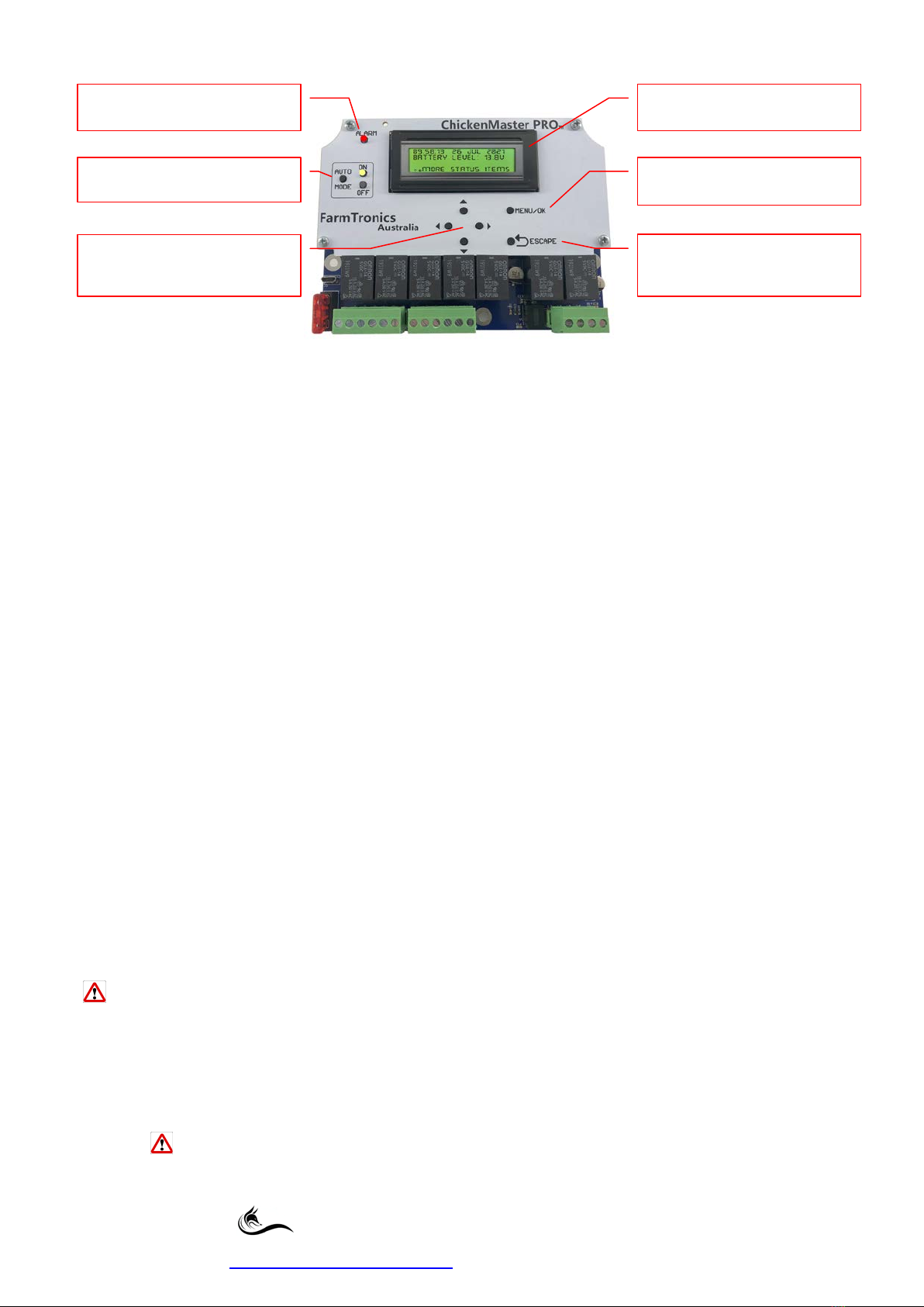
Description of Push Buttons and their Functions:
•Pressing any button will turn ON the LCD Backlight, it will turn OFF after 60 Seconds of inactivity.
•If the User is in any of the MENU/STATUS Screens with longer than 60 Seconds of inactivity the
display will return to the MAIN Home Screen.
•From the MAIN HOME screen, pressing the MENU/OK button once will enter the SETTINGS MENU.
•Every time the ESCAPE button is pressed, returns the user back up one level in the MENU Structure
and will abort any changes made if the user was entering data.
•Pressing the MENU/OK button will accept any data entered, and then move back to the previous
screen.
•UP button increments a step UP every time it is pressed;
holding down for 2 Seconds initiates the fast scroll feature.
•DOWN button increments a step DOWN every time it is pressed;
holding down for 2 Seconds initiates the fast scroll feature.
•RIGHT button increments to the RIGHT every time it is pressed.
•LEFT button increments to the LEFT every time it is pressed.
•AUTO MODE button toggles between AUTO ON and AUTO OFF Mode.
(AUTO ON Mode is the default on every boot up regardless of what mode the
ChickenMaster PRO was in prior to boot up).
•AUTO ON LED stays lit in AUTO ON Mode.
•AUTO OFF LED pulses ON & OFF once every second in AUTO OFF Mode.
•RED ALARM LED pulses ON & OFF twice every second when an alarm is triggered.
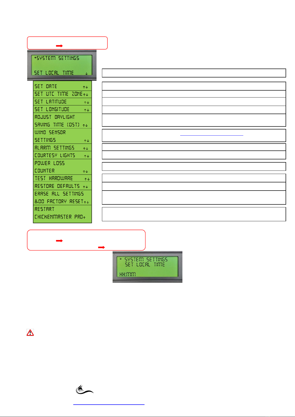
Initial Boot Up Procedure:(or after an ERASE ALL SETTINGS & DO FACTORY RESET)
On initial out of the box power up the User will be prompted to enter the following values before the
ChickenMaster PRO can be used.
Date, Daylight Saving Time (DST), Local Time, UTC Time Zone, Latitude & Longitude
Once the above data has been entered the Main Home Screen will be displayed.
Please refer to the ChickenMaster PRO Quick-Start Guide on Page 43.
If the ChickenMaster PRO has been powered down for longer than 120 Hours causing the Internal
Battery to run flat then the Initial Boot up Procedure will initiate again on power up.
Other than the first boot up requirements all previously entered USER settings will remain unchanged and
will NOT be erased.
The ERASE ALL SETTINGS & DO FACTORY RESET (Page 23) also initiates the
Initial Boot Up Procedure and Installs all the Factory Default Values. (See Default Value Tables on pages 39,
40 & 41)ALL USER settings will be deleted when this option is selected.
Enters MENU MODE & Accepts any
changes that have been made
ABORTS changes made & goes back UP
one level in the MENU structure each
time it is pressed
ALARM LED will flash when an alarm
threshold is triggered
AUTO MODE Button Enables or
Disables all Automatic Mode Functions
Allows UP, DOWN, LEFT & RIGHT
movement through the Menus &
Status Screens
4 Line, 20 Character per line LCD
Display with Backlight

Page 2of 43
ChickenMaster PRO User Guide
Firmware 01.14B Revision 1.0 23/05/2022
The Den, 100 Fox Drive, Dandenong South. Victoria. 3175.
www.farmtronics.com.au Phone: 0411 479 411
HOME SCREEN (1) & STATUS SCREENS (1 to 15)
The following two screens depict what the User will see on the Main Home Screen when the
ChickenMaster PRO is in a rest state.
MAIN Home Screen (With the Wind Sensor DISABLED; this is the DEFAULT Screen)
MAIN Home Screen (With the Wind Sensor ENABLED)
Pressing the UP or DOWN buttons from the MAIN Home Screen will scroll the User through the various
STATUS screens.
There are FIFTEEN Status screens displaying a multitude of information at the Users fingertips.
Items pictured below each Status Screen are the various statuses that can be displayed individually
on that screen at any one time.
Dual line Status information is displayed on line positions 3 and 4.
Single lines Status information is displayed on line 4 only.
Status Screen 1 of 15 - EXTERNAL DOORS
EIGHT individual status screens are available.
< Line 3
< Line 4
Automatic Mode has been DISABLED via the Settings Menu or the AUTO Mode is in AUTO Mode OFF
External Doors have had MANUAL Intervention or the ChickenMaster PRO has just been powered up so their
position is UNKNOWN. The External Doors will be Automatically OPENING at the time displayed
External Doors have had MANUAL Intervention or the ChickenMaster PRO has just been powered up so their
position is UNKNOWN. The External Doors will be Automatically CLOSING at the time displayed
External Doors are currently OPEN and the next scheduled CLOSING time is displayed
External Doors are currently CLOSED and the next scheduled OPENING time is displayed
External Doors are currently CLOSED based on a scheduled event and will go to a WIND SAFE position when
the scheduled OPENING time triggers. I.e. WIND SAFE MODE has been triggered 10 Minutes prior to opening
External Doors are currently OPEN based on a scheduled event but have gone to a WIND SAFE minimum
position. CLOSING time displayed is the next CLOSE scheduled event.
I.e. WIND SAFE MODE has been triggered
External Doors are in a VOLTAGE LOCKOUT state and will not operate either automatically or manually
Line 1: Displays the current TIME and DATE
Line 2: Displays the BATTERY LEVEL in VOLTS
Line 4: Use the UP & DOWN Buttons to scroll through the eleven STATUS Screens
Line 3: Displays the WIND SPEED in Kilometres per Hour (Only visible when the Wind Sensor is ENABLED)

Page 3of 43
ChickenMaster PRO User Guide
Firmware 01.14B Revision 1.0 23/05/2022
The Den, 100 Fox Drive, Dandenong South. Victoria. 3175.
www.farmtronics.com.au Phone: 0411 479 411
Status Screen 2 of 15 – DOOR SCHEDULE
FOUR Individual status screens are available.
Status Screen 3 of 15 – NEST BOX GATES
SIX Individual status screens are available.
Status Screen 4 of 15 – NEST BOX SCHEDULE
FOUR Individual status screens are available.
Automatic Mode has been DISABLED via the Settings Menu or the AUTO Mode is in AUTO Mode OFF
NEST BOX GATES have had MANUAL Intervention or the ChickenMaster PRO has just been powered up so
their position is unknown. They will be Automatically OPENING at the time displayed
NEST BOX GATES have had MANUAL Intervention or the ChickenMaster PRO has just been powered up so
their position is unknown. They will be Automatically CLOSING at the time displayed
NEST BOX GATES are currently OPEN and the next scheduled CLOSING time is displayed
NEST BOX GATES are currently CLOSED and the next scheduled OPENING time is displayed
NEST BOX GATES are in a VOLTAGE FAILSAFE OPEN position. This has occurred because the battery voltage is
low. Automatic & Manual operation are locked out and the Nest Box Gates will revert to their next
scheduled position once the battery voltage reaches 1 volt higher than the user programmed VOLTAGE
NEST BOX GATES are currently CLOSED and the next scheduled OPENING and CLOSING times are displayed
NEST BOX GATES are currently OPEN and the next scheduled CLOSING and OPENING times are displayed
Automatic Mode has been DISABLED via the Settings Menu or the AUTO Mode is in AUTO Mode OFF
NEST BOX GATES are in a VOLTAGE FAILSAFE open state.
EXTERNAL DOORS are currently CLOSED and the next scheduled OPENING and CLOSING times are displayed
EXTERNAL DOORS are currently OPEN and the next scheduled CLOSING and OPENING times are displayed
Automatic Mode has been DISABLED via the Settings Menu or the AUTO Mode is in AUTO Mode OFF
EXTERNAL DOORS are in a VOLTAGE LOCKOUT state and will not operate either automatically or manually

Page 4of 43
ChickenMaster PRO User Guide
Firmware 01.14B Revision 1.0 23/05/2022
The Den, 100 Fox Drive, Dandenong South. Victoria. 3175.
www.farmtronics.com.au Phone: 0411 479 411
Status Screen 5 of 15 – INTERNAL LIGHTING
SIX Individual status screens are available.
Status Screen 6 of 15 – TODAYS DAYLIGHT LENGTH REQUIREMENT PERIODS (DLR)
TWO Individual status screens are available.
Status Screen 7 of 15 – SUNRISE/SUNSET TODAY
TWO Individual status screens are available.
Status Screen 8 of 15 – DAYLIGHT SAVING TIME
THREE Individual status screens are available.
INTERNAL LIGHTS are in a VOLTAGE LOCKOUT state and will not operate either automatically or manually
INTERNAL LIGHTING is currently ON and the next scheduled TURNING OFF time is displayed
INTERNAL LIGHTING is currently OFF and the next scheduled TURNING ON time is displayed
INTERNAL LIGHTING is currently ON and the ChickenMaster PRO has been switched to the AUTO OFF Mode
or Automatic Mode for the INTERNAL LIGHTING is DISABLED via Settings. I.e. MANUAL Control was used
INTERNAL LIGHTING is currently OFF and the ChickenMaster PRO has been switched to the AUTO OFF Mode
or Automatic Mode for the INTERNAL LIGHTING is DISABLED via Settings. I.e. MANUAL Control was used
Required DAYLIGHT LENGTH is OK and there is no requirement for the use of any artificial lighting
Daylight Saving Time is NOT active, NO DST ADJUSTMENT
Daylight Saving Time is active, 1 Hour has been added to all Time Clock Events and the LOCAL TIME
Daylight Saving Time is active, 30 Minutes has been added to all Time Clock Events and the LOCAL TIME
Line 3, shows the Morning ON & OFF Times based on the calculated Day Light Length Requirement Period
Line 4, sho ws the Evening ON & OFF Times based on the calculated Day Light Length Requirement Period
INTERNAL LIGHTS are in a VOLTAGE LOCKOUT state and will not operate either automatically or manually
Automatic Mode has been DISABLED via the Settings Menu or the AUTO Mode is in AUTO Mode OFF
Line 3, shows the time when SUNRISE will occur for Today
Line 4, shows the time when SUNSET will occur for Today
Feature has been DISABLED via the Settings, External Door or Internal Lighting Menus
Required DAYLIGHT LENGTH is OK and there is no requirement for the use of any artificial lighting

Page 5of 43
ChickenMaster PRO User Guide
Firmware 01.14B Revision 1.0 23/05/2022
The Den, 100 Fox Drive, Dandenong South. Victoria. 3175.
www.farmtronics.com.au Phone: 0411 479 411
Status Screen 9 of 15 – WIND SENSOR
FOUR Individual status screens are available.
Status Screen 10 of 15 – COURTESY LIGHTS
FOUR Individual status screens are available.
Status Screen 11 of 15 – LOW BATTERY ALARM
THREE Individual status screens are available.
Status Screen 12 of 15 – EXTERNAL ALARM INPUT
THREE Individual status screens are available.
WIND SAFE Mode has been triggered due to a high wind event. MINUTES Left is the value of the WIND SAFE
Lockout Interval & will count down to zero, after which the DOORS will revert back to their normal position
Feature has been DISABLED via the Settings Menu
Automatic Mode has been DISABLED via the Settings Menu or the AUTO Mode is in AUTO Mode OFF
COURTESY LIGHTS are currently ON. MINUTES LEFT is the time remaining before the lights will switch OFF
COURTESY LIGHTS are currently OFF
Feature has been ENABLED via the Settings Menu and is actively sensing Wind Speed
Feature has been DISABLED via the Settings Menu
COURTESY LIGHTS are in a VOLTAGE LOCKOUT state and will not operate either automatically or manually
Feature ENABLED via the Settings Menu and a LOW BATTERY ALARM was TRIGGERED at the Voltage value
shown
Feature has been DISABLED via the Settings Menu
Feature ENABLED via the Settings Menu but NO ALARM is active
Feature ENABLED via the Settings Menu and the EXTERNAL ALARM INPUT was TRIGGERED
Feature has been DISABLED via the Settings Menu
Feature ENABLED via the Settings Menu but NO ALARM is active

Page 6of 43
ChickenMaster PRO User Guide
Firmware 01.14B Revision 1.0 23/05/2022
The Den, 100 Fox Drive, Dandenong South. Victoria. 3175.
www.farmtronics.com.au Phone: 0411 479 411
Status Screen 13 of 15 – STROBE LIGHT
TWO Individual status screens are available.
Status Screen 14 of 15 – POWER LOSS COUNTER
Status Screen 15 of 15 – FIRMWARE VERSION
STROBE LIGHT is in a STANDBY MODE and waiting for a User programmed ALARM event to occur
STROBE LIGHT is in a User programmed ALARM Condition and currently FLASHING.
Displays the total amount of POWER OUTAGES that have occurred since initial power up or after the Power
Loss Counter was reset to zero via the SETTINGS Menu.
Displays the current FIRMWARE VERSION of your ChickenMaster PRO
End Status Screens

Page 7of 43
ChickenMaster PRO User Guide
Firmware 01.14B Revision 1.0 23/05/2022
The Den, 100 Fox Drive, Dandenong South. Victoria. 3175.
www.farmtronics.com.au Phone: 0411 479 411
MAIN SETTINGS MENU
SIX Sub Menu Items are available.
Main Settings Menu
MANUAL CONTROL MENU
Main Settings Menu
Manual Control
EXTERNAL DOORS
Pressing and HOLDING the UP arrow button will OPEN the EXTERNAL DOORS.
Pressing and HOLDING the DOWN arrow button will CLOSE the EXTERNAL DOORS.
MANUAL CONTROL of the External Doors can be used even if the ChickenMaster PRO is in the
AUTO OFF position or if the External Doors AUTOMATIC MODE has been DISABLED in settings.
EXTERNAL DOORS are inhibited from operating in MANUAL Control Mode when the
VOLTAGE LOCKOUT Threshold has been reached.
The default Value for this threshold is 11.0 Volts (User Adjustable) with a 1 volt positive Hysteresis (Fixed)
Attempting manual control of the External Doors during VOLTAGE LOCKOUT will display the following screen.
Press the ESCAPE button to exit this screen.
EXTERNAL DOORS settings
SYSTEM SETTINGS required for your ChickenMaster PRO to function correctly
MANUAL CONTROL allows the user to manually control, EXTERNAL DOORS, NEST BOX GATES, INTERNAL
LIGHTING, COURTESY LIGHTS & TEST ALARM/STROBE
INTERNAL LIGHTING settings
NEST BOXES GATES settings
Logs numerous events for fault finding refer page 38 for a list of the types events logged

Page 8of 43
ChickenMaster PRO User Guide
Firmware 01.14B Revision 1.0 23/05/2022
The Den, 100 Fox Drive, Dandenong South. Victoria. 3175.
www.farmtronics.com.au Phone: 0411 479 411
Main Settings Menu
Manual Control
NEST BOX GATES
Pressing and HOLDING the UP arrow button will OPEN the NEST BOX GATES.
Pressing and HOLDING the DOWN arrow button will CLOSE the NEST BOX GATES.
MANUAL CONTROL of the Nest Box Gates can be used even if the ChickenMaster PRO is in the
AUTO OFF position or if the Nest Box Gates AUTOMATIC MODE has been DISABLED in settings.
NEST BOX GATES will be inhibited from operating in MANUAL Control Mode when the
VOLTAGE FAILSAFE Threshold has been reached.
The default Value for this threshold is 11.0 Volts (User Adjustable) with a 1 volt positive Hysteresis (Fixed)
Attempting manual control of the Nest Box Gates during VOLTAGE FAILSAFE will display the following screen.
Press the ESCAPE button to exit this screen.
Main Settings Menu
Manual Control
INTERNAL LIGHTING
Pressing the UP arrow button ONCE will turn ON the INTERNAL LIGHTING.
Pressing the DOWN arrow button ONCE will turn OFF the INTERNAL LIGHTING.
MANUAL INTERNAL LIGHTING Control can also be used even if the ChickenMaster PRO is in the
AUTO OFF position or if the INTERNAL LIGHTING AUTOMATIC MODE has been DISABLED in settings.
INTERNAL LIGHTING will be inhibited from operating in MANUAL Control Mode when the
VOLTAGE LOCKOUT Threshold has been reached.
The default Value for this threshold is 11.5 Volts (User Adjustable) with a 1 volt positive Hysteresis (Fixed)
Attempting manual control of the Internal Lighting during VOLTAGE LOCKOUT will display the following
screen.
Press the ESCAPE button to exit this screen.

Page 9of 43
ChickenMaster PRO User Guide
Firmware 01.14B Revision 1.0 23/05/2022
The Den, 100 Fox Drive, Dandenong South. Victoria. 3175.
www.farmtronics.com.au Phone: 0411 479 411
Main Settings Menu
Manual Control
COURTESY LIGHTING
Pressing the UP arrow button ONCE will turn ON the COURTESY LIGHTING.
Pressing the DOWN arrow button ONCE will turn OFF the COURTESY LIGHTING.
The Courtesy Lights are on a Countdown timer so they cannot be left ON inadvertently.
MANUAL COURTESY LIGHTING Control can also be used even if the ChickenMaster PRO is in the
AUTO OFF position or even if the COURTESY LIGHTING AUTOMATIC MODE has been DISABLED in settings.
COURTESY LIGHTING will be inhibited from operating in MANUAL Control Mode when the
VOLTAGE LOCKOUT Threshold has been reached, or if the COURTESY LIGHTING feature has been DISABLED.
The default Value for this threshold is 11.5 Volts (User Adjustable) with a 1 volt positive Hysteresis (Fixed)
Attempting manual control of the COURTESY LIGHTING during VOLTAGE LOCKOUT will display
VOLTAGE LOCKOUT on the COURTESY LIGHTING manual control screen.
FEATURE DISABLED will appear if the Courtesy Lights have been DISABLED via the Settings Menu.
Main Settings Menu
Manual Control
TEST ALARM/STROBE
The Manual Control - TEST ALARM/STROBE is on a Countdown Timer set for 30 Seconds.
(No User Adjustment)
This gives the user enough time to initiate the test sequence and go outside the caravan or barn to
confirm the strobe is flashing.
Pressing the UP arrow button ONCE will turn ON the ALARM/STROBE and initiate the 30 second countdown
Timer.
Pressing the DOWN arrow button ONCE will turn OFF the ALARM/STROBE and cancel the 30 second Timer.
Normally used with a FarmTronics FT-SL 12VDC Strobe Light magnetically mounted on the outside of the
Caravan/Trailer or Laying Barn.
There is NO Voltage Lockout for this item.
End Manual Control Menu

Page 10 of 43
ChickenMaster PRO User Guide
Firmware 01.14B Revision 1.0 23/05/2022
The Den, 100 Fox Drive, Dandenong South. Victoria. 3175.
www.farmtronics.com.au Phone: 0411 479 411
Main Settings Menu
SYSTEM SETTINGS
Main Settings Menu
System Settings
SET LOCAL TIME
Using the UP or DOWN buttons you can scroll the time forward or back.
A fast scroll will occur by holding down the UP or DOWN Buttons for longer than 2 seconds.
Once the correct Local Time is SET pressing the MENU/OK button enters this value and moves the user back
to the main SYSTEM SETTINGS screen.
Pressing the ESCAPE button at any time aborts all changes and returns the user back up one level in the
MENU Structure.
When Day Light Saving Starts or Ends do NOT adjust the LOCAL TIME on the CLOCK, use the Daylight
Saving Menu instead. (Page 12)
Sets the UTC Time Zone for your region refer page 42
Sets the Date in Day, Month and Year format (DD MMM YYYY)
Sets the Local Time in 24 Hour time format HH:MM
Sets your Longitude in Degrees 000⁰ East or West refer page 42
Sets your Latitude in Degrees 00⁰ North or South refer page 42
Adjustment for Daylight Saving Time, + 30 Minutes, + 1Hour or No DST Adjustment
Wind Sensor Settings menu when used with a FarmTronics FT-WS Wind Anemometer
Sets a variety of options for the External Alarm Input, Battery Voltage and numerous Strobe/Alarm Triggers
Sets the Countdown Timer Interval for the courtesy lights
Returns the Power Loss Counter to ZERO
Runs a TEST hardware procedure testing all the ChickenMaster PRO Inputs and Outputs
Restores the system default settings, Refer to Tables on pages 39, 40 & 41
Erases ALL user settings and initiates a Full Factory Reset. The Initial Boot Up procedure will initiate after the
user presses MENU/OK, Refer Quickstart Guide on page 43
Powers down and restarts the ChickenMaster PRO.
NO User Settings are lost during this process.

Page 11 of 43
ChickenMaster PRO User Guide
Firmware 01.14B Revision 1.0 23/05/2022
The Den, 100 Fox Drive, Dandenong South. Victoria. 3175.
www.farmtronics.com.au Phone: 0411 479 411
Main Settings Menu
System Settings
SET DATE
Using the Arrow buttons you can move the cursor left or right and then up or down to scroll the dates.
A fast scroll will occur by holding down the UP or DOWN Buttons for longer than 2 seconds.
Once the correct DATE is displayed pressing the MENU/OK button enters this value and moves the user back
to the main SYSTEM SETTINGS screen.
Pressing the ESCAPE button at any time aborts all settings and returns the user back up one level in the
MENU Structure.
Main Settings Menu
System Settings
SET UTC TIME ZONE
The UTC Time Zone should be the STANDARD UTC do NOT include any Day Light Saving Offset.
User selects their local UTC Time Zone in HH:MM by using the UP or DOWN arrow buttons.
A fast scroll will occur by holding down the UP or DOWN Buttons for longer than 2 seconds.
If the user scrolls below 00:00 we have a negative (–) UTC TIME ZONE if the user scrolls from 00:00 or above
we have a positive (+) UTC TIME ZONE.
UTC TIME ZONE range is -12 to +14 Hours and scrolls in 15 Minute increments.
Pressing the ESCAPE button at any time aborts all settings and returns the user back up one level in the
MENU Structure, refer to Page 40 for a list of UTC Time Zones.
Main Settings Menu
System Settings
SET LATITUDE
User selects their local LATITUDE in Degrees by using the UP or DOWN arrow buttons.
A fast scroll will occur by holding down the UP or DOWN Buttons for longer than 2 seconds.
If the user scrolls below 00 we have a negative (–) SOUTHERN LATITUDE and if the user scrolls from 00 or
above we have a positive (+) NORTHERN LATITUDE.
Pressing the ESCAPE button at any time aborts all settings and returns the user back up one level in the
MENU Structure.

Page 12 of 43
ChickenMaster PRO User Guide
Firmware 01.14B Revision 1.0 23/05/2022
The Den, 100 Fox Drive, Dandenong South. Victoria. 3175.
www.farmtronics.com.au Phone: 0411 479 411
Main Settings Menu
System Settings
SET LONGITUDE
User selects their local LONGITUDE in Degrees by using the UP or DOWN arrow buttons.
A fast scroll will occur by holding down the UP or DOWN Buttons for longer than 2 seconds.
If the user scrolls below 000 we have a negative (–) WESTERN LONGITUDE and if the user scrolls from 000 or
above we have a positive (+) EASTERN LONGITUDE.
Pressing the ESCAPE button at any time aborts all settings and returns the user back up one level in the
MENU Structure.
Main Settings Menu
System Settings
ADJUST DAYLIGHT SAVING TIME (DST)
Default value = NO DST ADJUSTMENT
At the END of a Day Light Saving Time period set to NO DST ADJUSTMENT.
When Day Light Saving Starts or Ends do NOT adjust the LOCAL TIME on the CLOCK, use this menu
instead.
At the START of a Day Light Saving Time period select the appropriate forward time,
+ 30 MINUTES or
+ 1 HOUR
DST Example:
If Plus 1 Hour is selected then the following changes would occur.
1. Local Time would advance forward by 1 Hour
If the following items are set to Time Clock Modality:
2. External Doors OPEN Time would advance by 1 Hour
3. External Doors CLOSE Time would advance by 1 Hour
4. Nest Box Gates OPEN Time would advance by 1 Hour
5. Nest Box Gates CLOSE Time would advance by 1 Hour
6. Internal Lights AM On Time would advance by 1 Hour
7. Internal Lights AM Off Time would advance by 1 Hour
8. Internal Lights PM On Time would advance by 1 Hour
9. Internal Lights PM Off Time would advance by 1 Hour
NO daylight saving adjustment has been set.
Adds 30 MINUTES to the local time and also all user Programmed Time Clock settings
Adds 1 HOUR to the local time and also all user Programmed Time Clock settings

Page 13 of 43
ChickenMaster PRO User Guide
Firmware 01.14B Revision 1.0 23/05/2022
The Den, 100 Fox Drive, Dandenong South. Victoria. 3175.
www.farmtronics.com.au Phone: 0411 479 411
Main Settings Menu
System Settings
WIND SENSOR SETTINGS
The wind sensor accepts a momentary closed contact pulse from the FarmTronics FT-WS Wind Anemometer.
The Automated Doors can close unexpectedly when a wind sensor is connected and ENABLED.
If you are intending to work inside the caravan behind an Automated Door, you must switch the
ChickenMaster PRO to AUTO OFF Mode.
(Remember to switch it back to AUTO ON Mode when you have finished your tasks)
Main Settings Menu
System Settings
Wind Sensor
AUTOMATIC MODE AVAILABILITY
Default value = DISABLED
Main Settings Menu
System Settings
Wind Sensor
SPEED LOCKOUT VALUE
Default value = 30 kph
If the wind speed exceeds this value then the EXTERNAL DOORS will move to a WIND SAFE POSITION as
determined by the OPEN or CLOSE; DOOR RUNTIME SAFE INTERVALS. (Refer page 14)
Scenarios and Functionality
The Scenarios below assume the Controller is in AUTO ON MODE.
Scenario 1: During an OPEN PERIOD - the EXTERNAL DOORS are fully OPEN
(Either via a Time Clock or via Sunrise/Sunset setting) and the Speed Lockout Value is triggered.
The EXTERNAL DOORS will commence to close for the length of the Door Close Runtime Safe Interval; this
will be the External Doors Wind Safe Position.
(Example: If the External Doors take approximately 60 Seconds to close and if the Door Close Runtime Safe
Interval is set to 30 Seconds then the Doors will move to a halfway WIND SAFE position).
Enables/Disables this feature from working in Automatic Mode
Sets the Wind Speed Lockout value in Kilometres per hour
Password protected area! Installer options are factory set, making changes to these settings without
fully understanding their functionality may cause damage to the external doors

Page 14 of 43
ChickenMaster PRO User Guide
Firmware 01.14B Revision 1.0 23/05/2022
The Den, 100 Fox Drive, Dandenong South. Victoria. 3175.
www.farmtronics.com.au Phone: 0411 479 411
If the EXTERNAL DOORS have had MANUAL Intervention via the MANUAL Control menu then this places the
Doors in an UNKNOWN POSITION.
If a wind event occurs while in an UNKNOWN POSITION, so that the Controller can determine a known
position it will close the Doors for the EXTERNAL DOORS RUNTIME INTERVAL (Automatic Door Menu) and
then assume the DOOR OPEN RUNTIME SAFE INTERVAL position.
Scenario 2: During a CLOSED PERIOD - the EXTERNAL DOORS are fully CLOSED.
(Either via a Time Clock or Sunrise/Sunset setting)
If the EXTERNAL DOORS are set to OPEN at 06:00; Wind Events are logged for 10 minutes prior to opening
and if the Speed Lockout Value has been triggered during this time then at 06:00 the doors will commence
to open for the length of the Door Open Runtime Safe Interval, this will be the External Doors Wind Safe
Position.
The only time the Wind Sensor will not respond to Wind Events is if it is DISABLED or between a CLOSED to
OPEN Night Time Period (except for 10 minutes prior to opening) or the user has switched the controller
Mode to AUTO OFF.
Use the UP or DOWN buttons to select a value in Kilometres Per hour.
A fast scroll will occur by holding down the UP or DOWN Buttons for longer than 2 seconds.
Pressing MENU/OK saves the selected setting.
Pressing the ESCAPE button at any time aborts all settings and returns the user back up one level in the
MENU Structure.
Main Settings Menu
System Settings
Wind Sensor
INSTALLER OPTIONS
Installer Options allow the Installer and End User to be able to make critical changes to the WIND SENSOR
Settings. To obtain your password go to Register my ChickenMaster PRO
If requested use access code 2022and then complete the registration process to retrieve your
Installer Password.
If an incorrect PASSWORD is entered the word ERROR will appear as pictured below.
Pressing the ESCAPE button returns the user back up one level in the MENU Structure.
Once the correct PASSWORD has been entered the WIND SENSOR INSTALLER OPTIONS menu items are
available with the following 3 options.
Main Settings Menu
System Settings
Wind Sensor
Installer Options

Page 15 of 43
ChickenMaster PRO User Guide
Firmware 01.14B Revision 1.0 23/05/2022
The Den, 100 Fox Drive, Dandenong South. Victoria. 3175.
www.farmtronics.com.au Phone: 0411 479 411
LOCKOUT INTERVAL is a countdown timer which initiates when the Speed Lockout Value threshold is
reached.
This timer will also reset back to zero every time the Speed Lockout Value threshold is retriggered and then
starts counting down again.
The Lockout Interval prevents any further Automatic movement of the doors until it has timed out.
MANUAL CONTROL of the EXTERNAL DOORS is NOT prevented and if used would reset the timer back to
zero and place the EXTERNAL DOORS in an UNKNOWN POSITION.
If a wind event occurs while the EXTERNAL DOORS are in an UNKNOWN POSITION then the doors will
respond by fully closing and then opening to the EXTERNAL DOORS safe mode position as determined by the
DOOR OPEN RUNTIME SAFE INTERVAL.
Main Settings Menu
System Settings
Wind Sensor
Installer Options
LOCKOUT INTERVAL
Default value = 30 MINUTES
Main Settings Menu
System Settings
Wind Sensor
Installer Options
DOOR OPEN RUNTIME SAFE INTERVAL
Default value = 015 SECONDS
Sets the Wind Speed countdown timer in MINUTES and will initiate when the Wind Speed Lockout Value is
reached
Sets the amount of time in SECONDS that the DOOR will travel when opening to a Wind SAFE Mode Position
Sets the amount of time in SECONDS that the DOOR will travel when closing to a Wind SAFE Mode Position

Page 16 of 43
ChickenMaster PRO User Guide
Firmware 01.14B Revision 1.0 23/05/2022
The Den, 100 Fox Drive, Dandenong South. Victoria. 3175.
www.farmtronics.com.au Phone: 0411 479 411
Main Settings Menu
System Settings
Wind Sensor
Installer Options
DOOR CLOSE RUNTIME SAFE INTERVAL
Default value = 015 SECONDS
Main Settings Menu
System Settings
ALARM SETTINGS
Multiple EVENTS can trigger an Alarm Condition.
All ALARM conditions will flash the front panel RED ALARM LED.
The user can program the STROBE LIGHT to flash based on settings within the STROBE/ALARM TRIGGERS
menu.
The External Alarm Input can be used with any voltage free contact; an example could be a Float switch in a
Water Tank to detect a low water level condition.
Main Settings Menu
System Settings
Alarm Settings
EXTERNAL ALARM INPUT
Settings for the External Alarm Input functionality and features
Settings for the Low Battery Alarm functionality and features
Enables/Disables which Alarm triggers can flash the Strobe Light
Enables/Disables this feature
Sets if the External Alarm Input responds to either a NORMALLY Open or NORMALLY Closed contact to
initiate an Alarm

Page 17 of 43
ChickenMaster PRO User Guide
Firmware 01.14B Revision 1.0 23/05/2022
The Den, 100 Fox Drive, Dandenong South. Victoria. 3175.
www.farmtronics.com.au Phone: 0411 479 411
Main Settings Menu
System Settings
Alarm Settings
EXTERNAL ALARM INPUT
INPUT AVAILABILITY
Default value = DISABLED
Main Settings Menu
System Settings
Alarm Settings
EXTERNAL ALARM INPUT
INPUT MODALITY
Default value = NORMALLY OPEN CONTACT
Main Settings Menu
System Settings
Alarm Settings
LOW BATTERY ALARM
Main Settings Menu
System Settings
Alarm Settings
LOW BATTERY ALARM AVAILABILITY
Default value = ENABLED
Enables/Disables this feature
Sets the Alarm Threshold Value in VOLTS

Page 18 of 43
ChickenMaster PRO User Guide
Firmware 01.14B Revision 1.0 23/05/2022
The Den, 100 Fox Drive, Dandenong South. Victoria. 3175.
www.farmtronics.com.au Phone: 0411 479 411
Main Settings Menu
System Settings
Alarm Settings
LOW BATTERY ALARM THRESHOLD VALUE
Default value = 11.5 VOLTS
Main Settings Menu
System Settings
Alarm Settings
STROBE TRIGGERS
Main Settings Menu
System Settings
Alarm Settings
Strobe Triggers
VOLTAGE LOCKOUT EXTERNAL DOORS
Default value = ENABLED
Enables/Disables the Strobe from flashing when a Voltage Lockout for the External Doors has occurred
Enables/Disables the Strobe from flashing when a Voltage Failsafe for the Nest Box Gates has occurred
Enables/Disables the Strobe from flashing when a Voltage Lockout for the Internal Lighting has occurred
Enables/Disables the Strobe from flashing when a Voltage Lockout for the Courtesy Lights has occurred
Enables/Disables the Strobe from flashing when a Wind Safe Mode Alarm has occurred
Enables/Disables the Strobe from flashing when an External Alarm Input event has occurred
Enables/Disables the Strobe from flashing when a Low Battery Voltage Event has occurred

Page 19 of 43
ChickenMaster PRO User Guide
Firmware 01.14B Revision 1.0 23/05/2022
The Den, 100 Fox Drive, Dandenong South. Victoria. 3175.
www.farmtronics.com.au Phone: 0411 479 411
Main Settings Menu
System Settings
Alarm Settings
Strobe Triggers
VOLTAGE FAILSAFE NEST BOX GATES
Default value = ENABLED
Main Settings Menu
System Settings
Alarm Settings
Strobe Triggers
VOLTAGE LOCKOUT INTERNAL LIGHTING
Default value = ENABLED
Main Settings Menu
System Settings
Alarm Settings
Strobe Triggers
VOLTAGE LOCKOUT COURTESY LIGHTS
Default value = DISABLED
Main Settings Menu
System Settings
Alarm Settings
Strobe Triggers
WIND SAFE MODE ALARM TRIGGERED
Default value = DISABLED

Page 20 of 43
ChickenMaster PRO User Guide
Firmware 01.14B Revision 1.0 23/05/2022
The Den, 100 Fox Drive, Dandenong South. Victoria. 3175.
www.farmtronics.com.au Phone: 0411 479 411
Main Settings Menu
System Settings
Alarm Settings
Strobe Triggers
EXTERNAL ALARM INPUT TRIGGERED
Default value = DISABLED
Main Settings Menu
System Settings
Alarm Settings
Strobe Triggers
LOW BATTERY VOLTAGE ALARM
Default value = ENABLED
Main Settings Menu
System Settings
COURTESY LIGHTS
COURTESY LIGHTS can be switched ON or OFF by an external momentary push button or via the MANUAL
CONTROL Menu.
Any of these inputs will initiate the Courtesy Light Countdown Timer.
Pressing any of the push buttons momentarily will start the countdown timer and turn ON the Courtesy
Lights.
Pressing again momentarily would reset the countdown timer and switch the Courtesy Lights OFF.
The Voltage LOCKOUT will inhibit the Courtesy Lights from working and if triggered, the ALARM Front
Panel LED will flash and if the Strobe option is ENABLED the external Strobe Light will flash.
The COURTESY LIGHTS Status screen (10) will also display VOLTAGE LOCKOUT.
Enables/Disables this feature
Sets the Countdown Timer Interval in Minutes
Enables/Disables the Voltage Lockout feature
Sets the Voltage Lockout Value in Volts
Table of contents