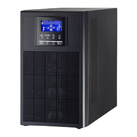
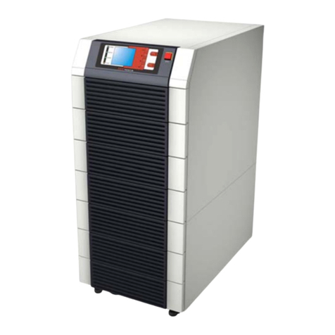
Voltronic Power Taurus UPS-7.5 User manual

7” Touch LCD Online UPS
208V 7.5K-60KVA
400V 10K-200KVA
Uninterruptible Power Supply System
User Manual

GENERAL
IN
DEX
1. INTRODUCTION.
1.1 ACKNOWLEDGEMENT LE
T
TER.
2. INFORMATION FOR SAFETY.
2.1. USING THIS MANUAL.
2.1.1. Conventions and used symbols.
2.1.2. For more information and/or help.
2.2.
S
AFE
T
Y INSTRUCTIONS.
2.2.1. To keep in mind.
2.2.2. General safety warnings.
2.2.3. Safety warnings regarding batteries.
3. STANDARD AND QUALITY GUARANTEE.
3.1. DECLARATION OF THE MANAGEMENT.
3.2. STANDARD.
3.3. ENVIRONMENT.
4. PRESENTATION.
4.1. VIEWS.
4.1.1. Views of the equipment.
4.1.2 Legend corresponding to the equipment views.
4.2. DEFINITION AND STRUCTURE.
4.2.1. Structural diagram.
4.3. UPS FUNCTION STAGES.
4.3.1. I/O EMI filters.
4.3.2. Rectifier-PFC stage (AC/DC).
4.3.3. Batteries.
4.3.4. Inverter stage (DC/AC).
4.3.5. Static bypass stage.
4.3.6. Maintenance or manual Bypass.
4.3.7. Terminals for EPO.
4.3.8. Control panel.
4.3.9. Control software and communications.
4.3.9.1. Control software at low level.
4.3.9.2. Managing software of the equipment.
4.3.9.3. Communications.
4.4. OPERATING PRINCIPLE OF AN EQUIPMENT.
4.4.1. Normal operating ().
4.4.2. Mains fault operating ().
4.4.3. Operating with non-active inverter ().
4.4.4. Manual bypass operating ().
4.4.5. Smart Eco-mode operating.
4.4.6. Frequency converter operating.
4.5. OPERATING STRUCTURE OF A PARALLEL SYSTEM.
5. INSTALLATION.
5.1. RECEPTION OF THE EQUIPMENT.
5.1.1. Reception, packaging and contents.
5.1.2. Storage.
5.1.3. Transport until its location.
5.1.4. Location, immobilized and considerations.
5.1.4.1. Location for single equipment.
5.1.4.2. Location for parallel systems.
5.1.4.3. Equipment immobilized and levelled.
5.1.4.4. Preliminary considerations before connecting.
5.1.4.5. Preliminary considerations before connecting, as regards to
batteries and protections.
5.1.4.6. Access to inside the cabinet for its connection.
5.2. CONNECTION.
5.2.1. Connection to mains, terminals (X1 to X4).
5.2.2. Connection of separate static bypass line, terminals (X14 a X17).
UPS B version
o
nly.
5.2.3. Connection to the output, terminals (X6 to X9).
5.2.4. Connection to the battery terminals of the equipment (X11, X12
and X23), with the battery modules (X47, X48 and X49).
5.2.5. Connection to the input main protecting earth terminal (X5) and
the earth bonding terminal (X10) .
5.2.6. Relay COM port. Connector (X32).
5.2.7. RS-232 and RS-485 COM ports. Connector (X31).
5.2.8. EPO terminals (X50).
5.2.9. Auxiliary contact and battery temperature probe terminal strip.
5.2.9.1. Terminal strip, auxiliary contact of manual bypass switch (X51).
5.2.9.2.Terminal strip, auxiliary contact of output switch (X45).
5.2.9.3.Terminal strip, battery temperature probe (X34). For batteries in a
separate cabinet only.
5.2.10. Connection of parallel BUS (X36i) and (X36o).
5.2.10.1. Connection of the communication or BUS bundle (BC).
6. OPERATING.
6.1. PRELIMINARY CONSIDERATIONS.
6.2. START UP.
6.2.1. Control before start up.
6.2.2. Start up procedure.
6.2.2.1 Take into consideration about Master and Slave
6.3 SHUTDOWN OF ONE EQUIPMENT FROM THE PARALLEL SYSTEM
6.4 START UP THE PREVIOUS UPS AGAIN
6.5. COMPLETE SHUTDOWN OF UPS
6.6. EMERGENCY POWER OFF (EPO) OPERATION.
6.7. BYPASS MANUAL SWITCH (MAINTENANCE).
6.7.1. Principle of operation.
6.7.2. Transfer to maintenance bypass.
6.7.3. Transfer to normal operation.
7. DESCRIPTION OF THE CONTROL PANEL.
7.1. BASIC FUNCTIONS OF LCD TOUCH SCREEN.
7.2. SCREEN DESCRIPTION.
7.2.1 Main level (screen menu 0.0).
7.2.2 “Control”level (screen menu 1.0).
7.2.3. ‘‘Measure’’ level (screen menu 2.0).
7.2.4. ‘‘Setting”level (screen menu 3.0).
7.2.5. ‘‘Alarm’’ level (screen menu 4.0).
7.2.6. “Data Logger”level (screen menu 5.0).
8. MAINTENANCE, WARRANTY AND SERVICE.
8.1. BASIC MAINTENANCE GUIDE.
8.1.1. Battery fuses.
8.1.2. Batteries.
8.1.3. Fans.
8.1.4. Capacitors.
8.2. WA
RR
A
NT
Y CONDITIONS.
8.2.1. Warranty terms.
8.2.2. Out of the scope of supply.
9. ANNEXES.
9.1. PARTICULAR SPECIFICATIONS, EQUIPMENTS (LV).
9.2. TECHNICAL SPECIFICATIONS, EQUIPMENTS (HV).
9.2. GLOSSARY

1
1. INTRODUCTION.
1.1 ACKNOWLEDGEMENT LETTER.
We would like to thank you in advance for the trust you have placed
in us by purchasing this product. Read this instruction manual care-
fully in order to be familiar with its contents, because as much you
understand and know the equipment, the higher will be the
satisfaction degree, safety level and functionality optimization.
We remain at you entire disposal for any further information or any
query you should wish to make.
Yours
s
i
ncere
ly.
The equipment here described can cause important
physical damages due to wrong handling. This is why,
the installation, maintenance and/or fixing of the here
described equipment must be done by our staff or
specifically authorized personnel.
Although no effort has been spared to guarantee that the
information in this manual is complete and accurate, we are
not responsible for any errors or omissions that may exist.
The images included in this document are merely for
illustration and may not accurate represent the parts of the
equipment showed. However, the differences that may
arise will be smoothed or solved with the correct labelling on
the unit.
According to our policy of constant evolution, we reserve
the rights to modify the specifications, operating or
described actions in this document without prior
notification.
All reproduction, copy, third party concession,
modification or partial or total translation of this
manual or document, in any form or medium, without the
previous written authorization from our firm is
prohibited, reserving of the complete and exclusive
property right over itself.
2. INFORMATION FOR SAFETY.
2.1. USING THIS MANUAL
The purpose of this manual or publication is to provide instructions
regarding the safety and to give explanations about the procedures for
delivery, installation and operating of the equipment.
Read this manual carefully before starting or making any action on the
equipment and especially in those instructions regarding safety.
Keep this document for future reference and keep it on hand during
the installation and commissioning procedures.
In the next pages, the «equipment»or «unit»and «(S.T.S.)»terms,
are referred to the Uninterruptible Power Supply (UPS) and Service
and Technical Support respectively.
2.1.1. Conventions and used symbols.
Some of the symbols can be used and shown in the equipment,
batteries and/or in the description of this document. It is advisable
to understand their meaning.
«Danger of electrical discharge» symbol. Pay special
attention to this symbol because it has features and basic
safety information for personnel. Not to respect these
indications can result in serious injuries or even death due
to electrical discharges.
«Warning» symbol. Carefully pay attention to this symbol
because it has features and basic safety information for
personnel and device. Not to respect these indications can
cause damages in the device during installation or loads.
«Warning» symbol. The electrolyte may corrode the
metals, and it is harmful to contact the electrolyte with
human skin directly. For the environment it is also a big
contaminant.
Never touch the spilled electrolyte of the deposited rests in the
batteries and its surrounding with bare hands. Under no
circumstances, it has not to be ingested or in contact with the
eyes.
In case of accidental spillage act accordingly while
collecting the electrolyte, in accordance with the protocol of
your company.
«Explosion» risk. Batteries emits explosive gases during its
charge, risk of explosion exists when it’s short-circuited or on
fire. Do not leave conductive parts over the battery terminals,
high risk of short-circuit and explosion might happen if there is
any accumulated gas inside the equipment or battery enclosure.
Attention! Danger of tipping might occur during transport
on inclined areas and when removing battery trays without
stabilizing the unit in advance. Do not pull out more than
one tray at the same time, or the possibility of falling down
the equipment and/or entrapment might cause high risk of
serious injury to the operator.
Precaution! Pay attention to fan blades in operation or fans
can start operating automatically suddenly.
Attention! Hot or very hot surface, elements or parts.
Possible burns happen due to the high temperature.

2
Never touch or manipulate the components of the
electronic PCB with hands and without any protection
against electrostatic discharges (ESD). They are highly
destructive for most of the parts and they can cause
expensive breakdown.
«Main protective earthing terminal» symbol. Connect the
earth cables from the installation to this terminal.
«Earth bonding terminal» symbol. Connect the earth
cables from the load and the external battery cabinet to this
terminal.
«Notes of
information
»symbol. Additional topics that
complement th
e
basic procedures. These instructions are
important for the equipment use and its optimum efficiency.
It is mandatory to use insulated gloves to prevent possible
electri
ca
l discharges when manipulating the connections related
to batteries.
It is mandatory to wear insulated shoes to prevent possible
electrical discharges when manipulating the connections which
are related to batteries.
It is mandatory to wear protective glasses, tight and
appropriate work clothes without hanging parts.
Obligation to turn off the power supply or loads
connected to the output.
Read carefully the instructions in the manual.
Smoking, fire or any actions that make sparks around the
batteries are prohibited.
To pull connecting cables is prohibited. Use the suitable
mediums
to unplug the
connections
from terminals.
To touch with bare hands is prohibited due to risk of electric
shock when contacting with low potential parts. To open,
manipulate the components inside the equipment and/or
terminals and battery connections are prohibited for non-
authorized and non-qualified personnel.
To randomly turn on the switches or protections is
prohibited. All maneuvers should be done according to the
instruction manual.
In case that the acid in the batteries contact with parts of the
body, wash the contacted areas with plenty of water and go to
the nearest medical service.
Preservation of the environment: The presence of this
symbol in the product or in their associated documentation
states that, when the life cycle of product expires, it cannot
be disposed together with the domestic residuals. In order to
avoid possible damages to the environment, separate this
product from other residuals and recycle it suitably. The users
can contact with their provider or with the pertinent local
authorities to get the information of how and where they can
recycle and/or dispose the product correctly.
Any packaging material must be recycled in accordance
with the legal norms applicable to each country where the
equipment is installed.
Alternating current a.c..
Direct current d.c..
2.1.2. For more information and/or help.
For more information and/or help of your specific unit, request it to
our Service and Technical Support (S.T.S.).
2.2.
S
A
F
E
T
Y INSTRUCTIONS.
•
It is required to
check the installation information
on
the nameplate.
• Please remember that the UPS is an electrical
energy generator, so the end-user must take all the
needed cautions against direct and indirect
contact.
Its power supply relies on the batteries, and AC mains,
which are included or excluded in the case or cabinet of the
electronic parts of the equipment depending on the model and/
or extended autonomies.
When the
equipment
is ON, and the
batteries
are
connected
to the
equipment and its protections, if any, are turned “On,”the fact
that the UPS is connected or not connected to mains is irrelevant,
and neither is the protections of mains. The outlets or output
terminals will supply voltage when there is energy in the battery set.
•Compliance as regards to “Safety instructions“
i
s
mandatory, being the user the legal responsible
regarding
to its
observance and application. Read
them
carefully a
n
d
follow the stated steps in the established order, keep them for
future consultations that may arise.
• If the instructions are not in total or partial understood
and in special those ones referred to safety, do not
carry
on with the installation or
commissioning
tasks,
because
there
could be a at a risk of your or other persons’safety, being able
to make serious injuries even the death, also it can cause
damages to the equipment and/or loads and installation.
•The local electrical regulations and the different
restrictions of the client’s site can invalidate some
recommendations included in the manuals. When discrepancies
exist, the user has to comply with the local regulations.
• This equipment must be installed by qualified
personnel and for personnel with no specific
training, just act with the help of this manual.
A person is defined as qualified, if he has experience in
assembling, commissioning and perfect control operating of the
equipment, if (s)he has the requirements to do the job and if (s)he
has read and understand all the things described in this manual,
in particular the safety indications. Such preparation is
considered valid if it is certified by our (S.T.S.) only.
•Warning labels have to be placed in all primary switches, installed in
areas far away from the equipment, in order to warn the electrical
maintenance personnel of the presence of a UPS in the circuit.
The label shall contain the following text or an equivalent one:
Before operating in the
ci
r
c
u
i
t.
Isolate the Uninterruptible Power Supply (UPS).
Check the voltage of all terminals, including the
earth main protective earth.
Risk of UPS backfeed voltage.

3
•To manipulate the connected terminals of the
equipment, which has been already connected to mains,
wait for five minutes after its complete isolation, before taking
any action in it.
2.2.1. Points for Attention
• The UPS is supplied in complete package from factory in the
best way for its transport and shipment till you receive is. It is
recommended to remain it packaged until it arrives to its final
location.
• When serious damages are observed in the package, or its level
of damages can be sensed in the contents and/or the shock
indicator is in RED, handle the product according to the
instructions stated in the own label of transport control.
Keep the affected equipment isolated from other received
equipment, and wait the further inspection by qualified staff.
In case it has to be returned to the factory or your distributor
but the same package is in poor conditions, contact with the
appropriate person in order to agree the way and conditions for
its return.
• Respect the unpacking instructions, as well as the established
mode to remove the equipment from the pallet.
These operations require the manpower of at least two
persons.
• The equipment has to be always in vertical position.
When moving the equipment, consider the slope of the
ground or surface and the risk of tipping.
• Be careful not to lift heavy loads without other people’s help.
Please refer to the following recommendations:
, < 18 kg.
, 18 - 32 kg.
, 32 - 55 kg.
, > 55 kg.
• To avoid accidentally dropping equipment or any
damaged enclosure, do not start it up under any concept. This
kind of fault can cause fire or electrical discharge. Contact
with our (S.T.S.).
• Some models include casters to move it till its location. They
are not designed for long distances or constant movements.
The equipment shall be guided by two persons as minimum,
which will be placed on either side and oriented to the walking
direction.
• UPSs are electronic equipment. Avoid jolting or bouncing like
those produced by moving the equipment over an uneven or
wavy surface.
• When moving an equipment from a cold to a warm environment
and vice versa, condensation (small water drops) might occur on
the external and internal surfaces. Before installing a moving
equipment from another place or even package, the
equipment should be placed in the new location for a minimum
of two hours before making any action, with the purpose of
adapting it to the new environmental conditions and avoid
possible condensations.
The UPS has to be completely dry before starting any
installation task.
• Do not store, install or expose the equipment in corrosive,
wets, warm, dusty environments or with conductive parts and
never outdoors.
The best location for installation should be cool, dry and far
from heat sources and easy to access. If possible, place it in
an environment with temperature control.
• Avoid locating, installing or storing the equipment in places
with direct sunlight or high temperatures. Batteries might
damage and/or shorten its lifetime.
In the exceptional and long exposure of intense heat, batteries
can cause filtrations, overheating or explosions, which can
cause fires, burn or other injuries. High temperatures can also
make deformation in the plastic enclosure.
• Do not obstruct the cooling grids by inserting an y objects
through themselves or other orifices.
• Locate the equipment to the power supply outlet and supplied
loads as close as possible , leaving an easy access in case of
an urgent disconnection.
• All models with casters have four leveling feet at each corner of
the base, with the purpose of locking and level the unit.
Loosen them until they can be lifted from the ground.
With the help of a spanner, act on each one and loosen
them half round more against the ground.
For slightly uneven grounds, immobilize the equipment with
these leveling parts.
Check if the equipment is completely immobilized.
Fortuitously pulling out the connection cables from the
equipment will indirectly be avoided so unexpected
movements will not happen.
• Regarding any interventions inside the equipment, battery
cabinet and battery manipulation is a task reserved to
personnel with specific or qualified knowledge only and in
particular to (S.S.T.). It is mandatory to immobilize the
equipment with the leveling feet- stated in the previous point,
before doing any action.
Attention! Risk of tipping may happen when the
battery trays are moved without stabilizing the unit first.
Do not remove more than one tray at the same time. High risk
of injury may take place over the operators due to accident
shock of the possible equipment falling down and/or
entrapment.
• Leave a minimum of free space to cool the unit of:
25 cm at both sides.
50 cm at the rear side.
100 cm at the top side.
150 cm at the front side.
• It is recommended to leave an additional 75cm at both sides,
for possible interventions of the (S.T.S.) or the requisite
clearance of the connected cables to facilitate the movement
of the equipment.
• Do not cut, deteriorate or manipulate the electrical cables, or do
not put heavy objects on them. Any of these actions could
cause a short-circuit, fire or electrical discharge.
Check if the connected electrical cables, plugs and outlets are in
good conditions.

4
• All electrical cables for power supply have to be fixed to the
equipment and loads, interfaces, etc..., or to immovable parts
for fear of being stepped on them or becoming a medium or
exposing to fortuitous pulls.
• Be careful not to wet the device because it is not waterproofed.
Do not allow any kind of liquids to leak to; if it happens, shut it
down immediately and contact with the (S.T.S.).
• If it accidentally contacts with liquids or high density of saline
air, dry it with a soft and absorbent cloth quickly.
Check if any liquid leak to the unit and act accordingly.
• To clean the equipment, wipe it with a slightly damp cloth and
then dry it. Avoid liquids sprinkling or spillage that could enter
through the slots or cooling grids, which may cause fire or
electric shock.
Do not clean the equipment with detergent products that
contain alcohol, benzene, solvent or other inflammable
substances, and needless to say they contain abrasive,
corrosive liquids.
• Never manipulate the equipment with wet hands.
• If it is observed that the UPS exhausts smoke or toxic gas, shut it
down immediately and disconnect it from power supply. This
incident may cause fire or electrical discharge. Contact with our
(S.T.S.).
• Do not put either materials or parts over the equipment that
might obstruct the synoptic visualization of the product.
• Before using the UPS for first time or after a long period
of tim
e
(6 months maximum), it has to be connected to
the power supply to charge the batteries for at least 12
hours.
Although the equipment can operate with batteries discharged,
you should keep in mind the possible risk of mains fault during
the first operating hours. Thus, the available back up time of
the UPS batteries should be lower than the expected.
2.2.2. General safety warnings.
• All electrical cables connections and disconnections of the
equipment, including the controlled ones, should be done
without power supply and with switches on «O» or «Off»
position.
•Pay special attention to the labelling of the equipment
that warns the «Electrical shock hazard». It indicate
there are dangerous voltages inside the equipment.
Do not open, dismantle or adjust the equipment when the
operating action is not stated in this document. To manipulate
equipment for repairing is restricted to qualified staff only. In
case of maintenance or fault, consult to the closest (S.T.S.).
A part from the implicit risk of electrical shock, any action
which is not stated in this document alters the internal or
external of the equipment or just only the simple intervention
inside can expire the warranty.
• Some action requires to open the front door or to remove the
protection cover from the terminals, i.e. erection or
commissioning operation.
Once the respective actions are completed, recover the
equipment to it was, with the protection cover put back and front
door closed.
• To shut down the equipment completely, follow the instructions
in the start-up and shutdown chapter.
Consult the documentation before doing any action.
Awrong manipulation over the switches can cause
important production losses and/or failures in the
equipment.
•Protection Earth cable of the UPS drives the leakage current
of the load devices. An isolated earth cable has to be
in
stalled as part
of the
circuit
that
supplies
the
equipment.
Cross
cable
section and its features will be the same as the
powe
r
supply
cables, but with green strip and with or
without yellow strip.
• The protection earth must be connected to the frame or
metallic chassis of any electrical equipment, by means
of the foreseen terminal (in our case to the UPS, battery
cabinet when it is available and loads), assuring that it is
done before turning on the input voltage.
It is essential that cables feeding the loads have their respective
protection earth cable.
When circuits branches, i.e. by means of terminal strips, it is
essential to have a protection earth terminal in each one of
them.
• Check the quality and availability of the earth to see if it’s between
the defined parameters definedby the local or national regulations.
• During the normal UPS operation, the input power supply
cable can’t be disconnected because the earth cable of
general protection in the UPS and all loads connecting at
the output will be disconnected, either.
Due to the same reason, the earth cable of general protection
in the building or switchgear panel that supplies the UPS will not
be disconnected.
•
Cross cable sec
ti
ons
used to
supply the equipment and loads to
be
fed,
w
ill
be followed
acco
r
d
in
g
t
o
th
e
n
o
min
a
l
c
urr
e
nt
s
t
a
t
ed
in th
e
n
a
m
ep
l
a
t
e
l
abe
l of
the equipment, and respect the Low Voltage
Electrotechnical
Regu
lations
or
standards
of the country.
• UPS equipment can be manufactured in four different
configurations of Input-Output:
Three phase - Three phase.
Three phase - Single phase.
Single phase - Three phase.
Single phase - Single phase.
To correctly operate the UPS, it is necessary to use input
Neutral cable or an isolation transformer between the power supply
and the equipment.
• The UPS doesn’t modify the input neutral regime at its output.
Do not earth the output neutral.
When, it is needed to modify the output neutral regime, an
isolation transformer has to be located between the loads and
the equipment.
• In those models with separate bypass line, an isolation
transformer has to be located in both input lines
(rectifier input or static bypass), in order to avoid the
direct connection of the neutral lines at both lines through
the internal wiring of the equipment.
This is only applicable when the two power supplies come from
different lines, i.e.::
Two different electrical companies.

5
One electrical company and a generator, ...
• The installation will have input protections sized to the currents of
the equipment and stated in the nameplate label. (RCD devices
type B and circuit breakers with C characteristic or any other
equivalent one).
For equipment with three phase input, and connected to an IT
distribution system, the protection will be with four poles in order
to break the three phases and neutral in the same maneuvering.
Overload conditions are considered as a non-permanent and
exceptional operating mode, so these currents will not be kept in
mind when sizing the protections.
• Do not overload the UPS by connecting loads with inrush
consumptions at its output, i.e. laser printers.
• Installations with redundant equipment or separate bypass line,
there will be one and common RCD device only of 300 to
500mA for both lines at the beginning of the installation.
• It is recommended to distribute the output power into four lines at
minimum. Each one of them will have a protection circuit
breaker sized to the quarter of the nominal power. This kind of
outgoing distributions will allow any fault that makes a short
circuit in any device connected to the equipment to be affected to
the line with the failure only. Power supply will be guaranteed to
the rest of connected loads, because of the tripping of the
affected line by the short-circuit only.
• Under any concept the input power cables will be connected to
the output of the equipment, either directly or indirectly through
other outlets.
• When supplying input voltage to a UPS with static bypass
o
r separate bypass line, if the inverter is in «Off» (shutdown)
mode, it doesn’t mean no voltage at the output terminals.
To set no voltage, input and static bypass switches have to be turned
«Off».
Put warnings labels and/or emergency switches in the particular
installation if the safety norms require it.
• It is possible that the UPS supplies output voltage through the
manual bypass to those equipment through either standard or
optional mode under the consideration of safety.
If it is necessary to break the output supply of the equipment under
this situation, turn off the outgoing distribution protection or lack it, and
turn off the general protection of the distribution panel that feeds the
UPS.
• All the equipment have two auxiliary terminals to install an
external emergency power off button (EPO), which will belong to
the end-user.
EPO doesn’t affect the power supply of the equipment, but it only
breaks the power supply to the loads as a safety measure.
• RACK mounted equipment are destined to be installed in a predeter
mined
se
tting and to
be do
n
e
b
y professionals.
Its installation has to be designed and executed by qualified
personnel, who will be responsible for applying the safety
and EMC regulations and standards controlling the
particular installations and the place where the product is
destined.
2.2.3. Safety warnings regarding batteries.
•The manipulation and connection of the batteries shall
be done and supervised by personnel with battery
knowledge only.
If Battery circuit is not isolated from input voltage, it is
dangerous to touch any part of the batteries. Dangerous
voltages can be found between the terminals of the battery set
and the earth. Check if there is any voltage at the input before
taking any action over them.
• Before doing any action inside the UPS, disconnect the
ba
tt
e
ri
es
.
Check that no voltage is present and there is not potential danger in
th
e
D
C
BU
S
(capac
it
o
r
s)
o
r in th
e
e
n
dpo
int
o
f th
e
ba
tt
e
ry
se
t terminals.
• In equipment with separate battery cabinet, check if they are
compatible before connecting them.
• When faulty batteries are found, the complete battery set has
to be replaced. But with few exceptional cases in new
equipment due to manufacturing faults, it will only be replaced
the defective ones.
The replacement should be conducted with another battery in
same type, voltage, capacity, quantity and the same brand.
Otherwise there is a risk of explosion.
• Do not reuse faulty batteries. There could be a risk of
explosion or burst in any battery with the involved problems
and issues.
• Generally supplied batteries are installed in the same cabinet,
case or rack of the equipment. Depending on the power,
autonomy or both, they can be supplied separately from the
equipment in another cabinet, case or rack, with the interlink
cables among them. Do not modify its length.
•In those equipment without batteries, their acquisition, installation
and connection will be done by the end-user and it should be
under his/her responsibility. Information about the batteries
as regards to quantity, capacity and voltage, is stated in the
battery label stuck beside the nameplate of the equipment.
Respect these data, battery connection polarity and the
supplied circuit diagram strictly.
For an optimum and efficient operation, the battery set has to
be located as close to the equipment as possible.
• Battery voltage can involve the risk of electric shock and
can produce high short-circuited currents. Observe the
following preventive measures before manipulating any
terminal block identified in the labelling as «Batteries»:
Use the suitable IPE (Individual Protection Equipment): gloves
and insulated shoes, protection glasses, suitable work clothes,
and etc.
Take off rings, bracelets or other metal hanging objects.
Use tools with insulated handles.
Disconnect the corresponding protection elements.
When connecting a battery cabinet to the UPS, respect the
polarity and color of the cables (red-positive; black-negative)
indicated in the manual and labelling.
Do not place metal tools or objects over the batteries.

6
Risk of short-circuit and possible deflagration may
happen due to the accumulated hydrogen.
Metallic particles of different sizes should be avoided due
to the violent explosion of the short-circuit and/or the tool
itself or the metallic object. This might result in the incident,
and increase the risk of significant damage to nearby
people and other devices, instruments or machines.
Never manipulate them with your bare hands or through
conducting objects. Both the battery terminal block of the
equipment and the ones from the batteries are necessary.
In case the automatic software to shut down the devices
due to end of back up time is not set, it is recommended to
shut down the loads and the UPS before depleting the
autonomy of the batteries, as a preventive safety measure
for the own loads.
•If the equipment is not in operation during the nighttime,
weekends and holidays periods, it is recommended to shut
down the equipment completely. In particular due to this last
period and safety reasons, the energy generator should be
handled with care, especially to prevent batteries from
unnecessarily discharging during these periods of time.
•When the equipment and/or battery module is protected by fuse
which is needs to be replaced, substitute it for another one with
the same type, format and size.
•After prolonged time of disconnection, it is needed to recharge
the batteries for 12 hours at a minimum every 6 months, in order
to avoid the irreversible degradation of the batteries.
•The battery terminals are requisite in order to avoid the high risk
of detriment to the equipment and batteries.
•Avoid mechanical efforts and impacts.
•Do not open or mutilate the battery. Spilled electrolyte is harmful
and toxic for the skin and eyes.
•Do not dispose the batteries in a fire or expose it to high
temperatures. Batteries may explode.
•If acid contacts with parts of the body, wash it immediately with
plenty of water and urgently call the nearest medical service.
•Batteries involve a possible risk for health and environment so the
disposal should be done in accordance with the existing
regulations.

7
3. STANDARD AND QUALITY GUARANTEE.
3.1. DECLARATION OF THE MANAGEMENT.
Our target is to fulfill the client’s satisfaction; therefore, this
Management has decided to establish a Quality and Environmental
policy, by means of installation a Quality and Environmental
Management System that enable us to comply with the
requirements demanded by the standard ISO 9001 and ISO
14001 and by our Clients and their concerns too.
Likewise, the enterprise Management is committed with the
development and improvement of the Quality and Environmental
Management System, through:
The communication with all of our clients to fulfill their
satisfaction and legal requirements and regulations.
The Quality and Environmental Policy diffusion and the fixation
of the Quality and Environment targets.
To carry out revisions by the Management.
To provide the necessary resources.
3.2. STANDARD.
This product is designed, manufactured and commercialized in
accordance with the standard EN ISO 9001 of Quality
Management Systems. The marking shows the conformity
to the EEC Directive by means of the application of the following
standards:
• 2006/95/EC of Low Voltage Safety.
• 2004/108/EC of Electromagnetic compatibility (EMC).
In accordance with thespecifications of the harmonized standards.
Standards as reference:
• EN-IEC 62040-1. Uninterruptible power supply (UPS). Part 1-1:
General and safety requirements for UPS’s used in accessible
areas by end-users.
• EN-IEC 60950-1. IT equipment. Safety. Part 1: General
requirements.
• EN-IEC 62040-2. Uninterruptible power supply (UPS). Part 2:
EMC requirements.
The manufacturer’s responsibility excluded the event of any
modification or intervention in the product done by the end-
user.
This is a product for its use in commercial and industrial
applications, so restrictions and additional measures is
required in the installation to prevent perturbations, in
accordance with the particular standards, laws or
regulations for its use in critical applications.
Pay attention to those systems used in vital signs
maintenance, medical applications, commercial
transportation, nuclear power stations, as well as other
applications or loads where a failure in the product can
cause serious personal injuries or material damages.
Declaration of conformity CE of the product is at the client
disposa
l under previous request to our headquarters
offices.
3.3. ENVIRONMENT.
This product has been designed to respect the environment and has
been manufactured in accordance with the standard ISO 14001.
Equipment recycling at the end of its lifetime:
Our company commits to use the services of authorized venders
and to follow the regulations, in order to properly treat the
recovered product at the end of its lifetime (contact your distributor).
Packaging:
To recycle the packaging, follow the legal regulations in force,
depending on the particular standard of the country where the
equipment is installed.
Batteries:
The batteries mean a serious danger for health and environment.
The disposal of them must be done in accordance with the
regulations in force.

8
4. PRESENTATION.
4.1. VIEWS.
4.1.1.Views of the equipment.
Figures 1 to 20 show the illustrations of the equipment according to
different models, nominal operating voltages and input-output settings,
which are summarized in Chart 1.
Format of protections and size of the terminals shown in the figures
of this document always correspond to the highest power rate model
manufactured in that cabinet, at the same power supply voltage and
input-output setting.
Nevertheless by constant evolution of the products, some
discrepancies or small contradictions might arise. So, if any questions,
the labels on the equipment will prevail.
Each equipment model corresponds to one power rate,
voltage, frequency and input and output currents. All values
of these features can be checked in the nameplate, located
at the back of the front door (PF), and act in your installation
accordingly.
In the description of this manual, there are references to «LV» (Low
voltage) and «HV» (High voltage) abbreviations, described in the
nomenclature of the model with an «A » for «LV» and omitted «HV»,
grouping the following interval of voltages:
• LV.- 3x200 to 3x230 V (115 to 133 V in single phase).
• HV.- 3x380 to 3x415 V (220 to 240 V in single phase).
These abbreviations do not have any other purpose but matching
and/or helping to give a better comprehension of the detailed
information in this document and even they are not shown either in
the nomenclature, or in the reference of the nameplate model.
All models can operate as single units or connected in parallel with
other equipment of the same family because the necessary
electronic kit is included.
Connection in parallel can be done at any time when the upgrading
requirements are needed to increase the supplied power of the
equipment or in order to have redundant operating systems for
installations with higher safety.
Do not connect UPS equipment of different features versions,
settings, back up times or duplicated addresses (i.e.: two equipment,
although they are identical, coming from two parallel systems and
with the same address) in parallel.
In any parallel system only one and different address is assigned to
each equipment that makes the system.
Model.
Voltage (V)
Power (kVA / kW)
Fig. no. Front UPS cabinet
Fig. no. Front battery cabinet
Door closed
Door opened
Door closed
Door opened
UPS-7.5
«LV»
3x200.
3x230 V
(115. 133 V
in single
phase)
7.5 / 6.75
1
(*) 1 for (-B)
6
(*) 8 for (-B)
15
(Battery cabinet
for extended
back up time
models only)
16
(Battery cabinet
for extended
back up time
models only)
UPS-10
10 / 9
UPS-15
15 / 13,5
6
(*) 9 for (-B)
UPS-20
20 / 18
6
(*) 10for (-B)
UPS-30
30 / 27
7
15
16
UPS-40
40 / 36
2
11
17
18
UPS-50
50 / 45
12
UPS-60
60 / 54
UPS-80
80 / 72
3
13
19
20
UPS-100
100 / 90
UPS-10
«HV»
3x380.
3x415 V
(220. 240 V
in single
phase)
10 / 9
1
(*) 1 for (-B)
6
(*) 8 for (-B)
15
(Battery cabinet
for extended
back up time
models only)
16
(Battery cabinet
for extended
back up time
models only)
UPS-15
15 / 13.5
UPS-20
20 / 18
UPS-30
30 / 27
6
(*) 9 for (-B)
UPS-40
40 / 36
6
(*) 10for (-B)
UPS-60
60 / 54
1
7
15
16
UPS-80
80 / 72
2
11
17
18
UPS-100
100 / 90
2
12
UPS-120
120 / 108
UPS-160
160 / 144
4
13
19
20
UPS-200
200 / 180
(*) The equipment with separate static Bypass line (-B), are supplied in the same cabinet as basic models, less those ones stated in this
chart with other No of Fig..
Table 1. Reference relation among models and illustration.

9
Fig. 1. UPS front view from 7.5 to 30 kVA (LV) / 10 to 60 kVA (HV),
with or without separate static bypass line (-B).
Fig. 2. UPS front view from 40 to 60 kVA (LV) / 80 to 120 kVA (HV),
without separate static bypass and 40 kVA (LV) / 80 kVA
(HV) with separate static bypass (-B).

10
Fig.3. LCD Touch Screen View
(1) Equipment with extended back up time only.
Fig. 4.
UPS Front view with door opened. 7.5KVA to 20KVA (LV)/
10KVA to 40KVA (HV) models.
Fig. 5.
UPS Front view with door opened. 30KVA (LV)/ 60KVA (HV)
models.

11
Fig. 6.
UPS Front view with door opened. 7.5KVA to 10KVA (LV) /
10KVA to 20KVA (HV) models with separate static bypass line.
(UPS-B models)
Fig. 7.
UPS Front view with door opened. 15KVA (LV) / 30KVA (HV)
models with separate static bypass line (UPS-B models)

12
Fig. 8. UPS Front view with door opened, models 20KVA (LV) /
40KVA (HV) with separate static bypass line (UPS-B models)
Fig. 9. UPS front view with door opened, models 40kVA (LV) /
80KVA (HV).

13
Fig.
10. UPS front view with door opened, models 50 and 60 kVA (LV) / 100 and 120 kVA (HV), without separate
static bypass
line.

14
Fig.
11. UPS front view with door opened, models 80 and 100 kVA (LV) / 160 and 200 kVA (HV), without separate
static bypass
line.

15
(Q8)
(
X47
)
(
X4
9)
(
X48
)
(BF)
(
X
5)
(PR)
(
X10
)
Fig. 12. Battery cabinet front view No 1, with door closed. Fig. 13. Battery cabinet front view No 1, with door opened.

16
(Q8)
(X47)
(X49)
(X48)
(
X
5)
(PR)
(
X10
)
Fig. 14. Battery cabinet front view No 2, with door closed. Fig. 15. Battery cabinet front view No 2, with door opened.

17
Fig. 16. Battery cabinet front view No 3, with door closed. Fig. 17. Battery cabinet front view No 3, with door opened.

18
i
o
(X360)
(X32) (X36i )
(X50)
(X31)
(X31)
(X36)
(X36)
Fig. 18. Connection of communications for models up to 60 kVA
(LV) / 120 kVA (HV).
Fig. 19. Connection of communications for models higher than
60 kVA (LV) / 120 kVA (HV).
4.1.2 Legend corresponding to the equipment views.
Protection and maneuvering parts (Q*) in the UPS cabinet:
(Q1a) Input circuit breaker or switch according to the equipment
power rate, two or three poles respectively depending on
the mains typology.
(Q2) Output switch.
(Q3) Battery fuse holder switch with 3 fuses in models up to 20
kVA (LV) / 40 kVA (HV) or switch for B1 versions and higher
power rates models.
(Q4a) Static bypass switch, two or three poles depending on
the mains typology (-B version only).
(Q5) Manual bypass switch.
Protection and manoeuvring parts(Q*) in the battery cabinet:
(Q8) Battery fuse holder switch of 3 fuses, for models up to 60
kVA (LV) / 120 kVA (HV).
Battery switch, in models higher than 60 kVA (LV) / 120 kVA
(HV).
Connection parts (X*):
(X1) Terminal of input phase R.
(X2) Terminal of input phase S.
(X3) Terminal of input phase T.
(X4) Terminal of input neutral N.
(X5) Terminal (copper bar) of main earth ()
(X6) Terminal of output phase U.
(X7) Terminal of output phase V.
(X8) Terminal of output phase W.
(X9) Terminal of output neutral N.
(X10) Terminal (copper rod) of earth bonding for load or loads
and/or battery cabinet ().
(1) (X11) Battery positive terminal (+).
(1) (X12) Battery negative terminal (–).
(X14) Terminal of static bypass phase R (-B version only).
(X15) Terminal of static bypass phase S (-B version only).
(X16) Terminal of static bypass phase T (-B version only).
(X17) Terminal of static bypass neutral N (-B version only). (1)
(X23) Battery neutral N terminal (central tap).
(X31) DB9connector for COM RS-232 and RS-485 ports.
(X32) DB9 connector for relay interface.
(X34) Terminal strip of two terminals for temperature probe/floating
voltage. Equipment with sepa
r
a
t
e
battery cab
in
e
t
s
only.
(X36i
) HDB15 female connector, parallel bus input. Only useful in
parallel systems connection.
(X36o) HDB15 male connector, parallel bus output. Only useful in
parallel systems connection
(X45) Terminal strip of two terminals, auxiliary contact of output
switch. To be connected to its external homologous.
(X47) Battery positive terminal (+) of the battery cabinet.
(X48) Battery negative terminal (–) of the battery cabinet.
(X49) Battery neutral terminal N of the battery cabinet (central
tap).
(X50) External EPO terminals.
(X51) Terminal strip of two terminals, auxiliary contact of manual
bypass switch. To be connected to its external homologous.
(1): Battery terminals (X11), (X12) and (X23) available in
models > 20 kVA (LV) / > 40 kVA (HV) only, or in
equipment B1 type (extended back up time).
Other abbreviations:
(BC) Communication BUS bundle between equipment, of 5 m.
length with HDB15 connectors in both ends.
(BF) Rod to fix the connection wires of the equipment or battery
cabinet by means of wraps.
(BL) Mechanical lock for manual bypass switch (Q5).
(CL) Front door lock.
(LL) Key to lock and unlock (CL).
(PB) Levellers and fixing elements.
(PC) Control panel.
(PF) Front door.
(
X5
0)
(
X32)
This manual suits for next models
12
Table of contents
Other Voltronic Power UPS manuals

Voltronic Power
Voltronic Power Galleon II 3P User manual

Voltronic Power
Voltronic Power 1K Online UPS For Dual-mains Input User manual

Voltronic Power
Voltronic Power Winner series User manual

Voltronic Power
Voltronic Power +Power 30U-90 User manual

Voltronic Power
Voltronic Power 6K User manual

Voltronic Power
Voltronic Power Nano 400 User manual

Voltronic Power
Voltronic Power 6K User manual

Voltronic Power
Voltronic Power 6K User manual

Voltronic Power
Voltronic Power Galleon One 6K User manual

Voltronic Power
Voltronic Power 1K Online UPS For Dual-mains Input User manual